

Dual-Band and Dual-Polarization Patch Antenna with High Isolation ...
Dual-Band and Dual-Polarization Patch Antenna with High Isolation ...
Dual-Band and Dual-Polarization Patch Antenna with High Isolation ...

Create successful ePaper yourself
Turn your PDF publications into a flip-book with our unique Google optimized e-Paper software.
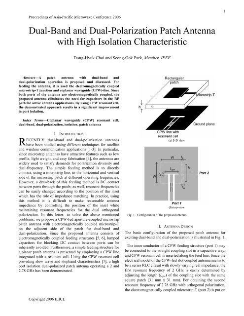
Proceedings of Asia-Pacific Microwave Conference 2006<strong>Dual</strong>-<strong>B<strong>and</strong></strong> <strong>and</strong> <strong>Dual</strong>-<strong>Polarization</strong> <strong>Patch</strong> <strong>Antenna</strong><strong>with</strong> <strong>High</strong> <strong>Isolation</strong> Characteristic1Dong-Hyuk Choi <strong>and</strong> Seong-Ook Park, Member, IEEEAbstract—A patch antenna <strong>with</strong> dual-b<strong>and</strong> <strong>and</strong>dual-polarization operation is proposed <strong>and</strong> discussed. Forfeeding the antenna, it is used the electromagnetically coupledmicrostrip-T junction <strong>and</strong> coplanar waveguide (CPW)-line. Sinceboth ports of the antenna are electromagnetically coupled, theproposed antenna eliminates the need for capacitors in the RFpath for active antenna applications. By using CPW resonant cell,the demonstrated approach results in a significant improvementin port isolation.Index Terms—Coplanar waveguide (CPW) resonant cell,dual-b<strong>and</strong>, dual-polarization, isolation, patch antennaRI. INTRODUCTIONECENTLY, dual-b<strong>and</strong> <strong>and</strong> dual-polarization antennashave been studied using different techniques for satellite<strong>and</strong> wireless communication applications [1-3]. In particular,since microstrip antennas have attractive features such as lowprofile, light weight, <strong>and</strong> easy fabrication [4], the antennas arewidely used to satisfy dem<strong>and</strong>s for polarization diversity <strong>and</strong>dual-frequency. The simple feeding method is to directlyconnect, using a microstrip line, to the horizontal <strong>and</strong> verticalside of the microstrip patch at different operating frequencies.However, a drawback of this feeding method is DC contactbetween ports through the patch; as well, resonant frequenciescan be easily changed according to the position of the insetwhich has the role of impedance matching. In practice, usingthis method it is difficult to make reasonable antennaimpedance by controlling the position of the inset whilemaintaining resonant frequencies for the dual orthogonalpolarization. In this letter, to solve the above mentionedproblems, we propose a CPW-fed aperture-coupled microstrippatch antenna <strong>with</strong> electromagnetically coupled microstrip-Ton the adjacent side of the patch for dual-b<strong>and</strong> <strong>and</strong>dual-polarization. Since the proposed antenna consists ofelectromagnetically coupled feeding structures [5, 6], lumpedcapacitors for blocking DC contact between ports can beinherently avoided. Furthermore, a simple feeding structure fora planar patch antenna is presented by employing a CPW lineintegrated <strong>with</strong> a resonant cell. Using the CPW resonant cellproviding slow wave <strong>and</strong> stopb<strong>and</strong> characteristics [7], a highport isolation dual-polarized patch antenna operating a 2 <strong>and</strong>2.78 GHz has been demonstrated.(a) 3-D view(b) top-viewFig. 1. Configuration of the proposed antenna.II. ANTENNA DESIGNThe basic configuration of the proposed patch antenna forexciting dual-b<strong>and</strong> <strong>and</strong> dual-polarization is illustrated in Fig. 1.The inner conductor of a CPW feeding structure (port 1) maybe connected to the straight coupling slot in a capacitive way,<strong>and</strong> CPW resonant cell is inserted along the feed line. Since theelectrical model of the CPW-fed slot coupled antenna seems tobe a series RLC circuit <strong>with</strong> slowly varying real impedance, thefirst resonant frequency of 2 GHz is easily determined byadjusting the length (l cpw ) of the coupling slot <strong>with</strong> the samesquare patch (31 mm x 31 mm). For obtaining the secondresonant frequency of 2.78 GHz <strong>with</strong> orthogonal polarization,the electromagnetically coupled microstrip-T (port 2) is put onCopyright 2006 IEICE
2the adjacent vertical side of the patch. Although the patch hasthe same length <strong>and</strong> width, the ground plane notched by theCPW-fed line makes it possible to shift up the secondfrequency. Since the microstrip-T junction acts as animpedance transformer, transforming the high input impedance3.5 GHz. The simulation result implies that high isolationcharacteristics may be occurred at 2.78 GHz b<strong>and</strong>. The designparameters of the fabricated antenna are: W = 31 mm, t l = 28mm, t w = 0.5 mm, t g = 0.1 mm, <strong>and</strong> c d = 0.8 mm. The measuredreturn loss <strong>and</strong> isolation characteristics of the proposed antennaare shown in Fig. 3. From the figure, it can be seen that twodistinct frequency b<strong>and</strong>s are excited at 2 GHz <strong>and</strong> 2.78 GHz,respectively. The measured return loss at port 1 was 8 dB lessthan the original value (-23 dB) of a one port CPW-fed slotantenna due to the variation of the imaginary impedance at port1 by attaching microstrip-T. Furthermore, it is demonstrated(a)(a) Return loss (——— port 1, – – – port 2)(b)Fig. 2. (a) Configuration of the CPW resonant cell. (b) MeasuredS-parameters for the CPW resonant cell.of the patch antenna to the desired low impedance, using thismethod it is easy to make reasonable antenna impedance bycontrolling the gap (t g ) <strong>and</strong> the length (t l ) of the microstrip-Twhile maintaining resonant frequencies for dual orthogonalpolarization. And we can easily solve the problem of DCcontact through the patch because both ports of the proposedantenna are electromagnetically coupled..III. EXPERIMENTThe antenna was fabricated on a 1.6 mm-thick FR-4 substrate<strong>with</strong> relative dielectric constant (ε r ) of 4.6, <strong>and</strong> measured usingan Agilent 8755 Network Analyzer. Fig. 2 shows thesimulation result of the CPW resonant cell (L cpw = 14 mm, L res =13.6 mm, t res_w = 2.2 mm, t res = 0.2 mm, <strong>and</strong> t res_g = 0.4 mm)placed λ/2, corresponding <strong>with</strong> 2 GHz, away from feedingpoint to avoid a variation of the antenna impedance. As shownclearly shown in the figure, the feed line has a stop b<strong>and</strong> at 2.5 –(b) <strong>Isolation</strong>Fig. 3. Measured S-parameter for the dual-b<strong>and</strong> <strong>and</strong> dual-polarizationpatch antennathat the isolation characteristic is suppressed to below –62 dB at2.78 GHz b<strong>and</strong>.Fig. 4 shows the measured radiation patterns of the antenna atthe center frequencies for dual feeding ports. It can be seenfrom the measured E-plane co-polarization <strong>and</strong>cross-polarization patterns that they are very similar to thesquare patch antenna. The radiation pattern is in the broadsidedirection <strong>with</strong> a cross-polarization level of 19.8 dB downcompared to the co-polarization level. The antenna gains are4.23 dBi (port 1) <strong>and</strong> 4.51 dBi (port 2), respectively.
3IV. CONCLUSIONA dual-b<strong>and</strong> <strong>and</strong> dual-polarization patch antenna based onboth the CPW-fed line <strong>and</strong> the microstrip-T line was fabricated<strong>and</strong> measured. By attaching a microstrip-T junction in thevertical side of the microstrip patch fed CPW line which isintegrated resonant cell, the proposed antenna has thedual-b<strong>and</strong> characteristic. In addition, this antenna has inherentDC isolation because the patch is electromagnetically coupledat both ports. This new type of antenna may be consideredpromising as an active antenna application which must use bothlayers.REFERENCES[1] Y. J. Kim, W. S. Yun, <strong>and</strong> Y. J. Yoon, “<strong>Dual</strong>-frequency <strong>and</strong>dual-polarisation wideb<strong>and</strong> microstrip antenna,” Electron. Lett., vol. 35,no. 17, pp. 1399-1400, 1999.[2] E. Lee, P. S. Hall, <strong>and</strong> P. Gardner, “Compact dual-b<strong>and</strong> dual-polarisationmicrostrip patch antenna, “Electron. Lett., vol. 35, no. 13, pp. 1034-1036,1999.[3] T. W. Chiou <strong>and</strong> K. L. Wong, “Broad-b<strong>and</strong> dual-polarized singlemicrostrip patch antenna <strong>with</strong> high isolation <strong>and</strong> low cross polarization,”IEEE Trans. <strong>Antenna</strong>s Propagat., vol. 50, no. 3, pp. 399-401, 2002.[4] C. A. Balanis, <strong>Antenna</strong> Theory: Analysis <strong>and</strong> Design. New York: Wiley,1997.[5] D. G. Kurup, A. Rydberg, <strong>and</strong> M. Himdi, “Compact microstrip-T coupledpatch antenna for dual polarisation <strong>and</strong> active antenna applications,”Electron. Lett., vol. 38, no. 21, pp. 1240-1241, 2002.[6] L. Giauffret, J. M. Laheurte, <strong>and</strong> A. Papiernik, “Study of various shapedof the coupling slot in CPW-fed microstrip antennas,” IEEE Trans.<strong>Antenna</strong>s Propagat., vol. 45, no. 4, pp. 642-647, 1997.[7] X. Quan, M. S. Kam, <strong>and</strong> H. C. Chi, “Novel 1-D microstrip PBG cells,”IEEE Microwave Guided Lett., vol. 10, no. 10, pp. 403-405, 2000.(a)(b)Fig. 4. (a) E-plane radiation patterns at port 1 (2 GHz). (b) E-planeradiation patterns at port 2 (2.78 GHz)(——— Co-polarization, – – – Cross-polarization)


