

Hexaband Planar Inverted-F Antenna With Novel Feed Structure for ...
Hexaband Planar Inverted-F Antenna With Novel Feed Structure for ...
Hexaband Planar Inverted-F Antenna With Novel Feed Structure for ...
- No tags were found...

You also want an ePaper? Increase the reach of your titles
YUMPU automatically turns print PDFs into web optimized ePapers that Google loves.
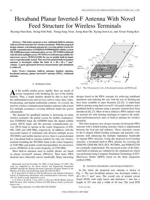
66 IEEE ANTENNAS AND WIRELESS PROPAGATION LETTERS, VOL. 6, 2007<strong>Hexaband</strong> <strong>Planar</strong> <strong>Inverted</strong>-F <strong>Antenna</strong> <strong>With</strong> <strong>Novel</strong><strong>Feed</strong> <strong>Structure</strong> <strong>for</strong> Wireless TerminalsByoung-Nam Kim, Seong-Ook Park, Young-Sang Yoon, Jeong-Kun Oh, Kyung-Joon Lee, and Gwan-Young KooAbstract—This letter proposes a new wideband built-in antennawith novel feed structure <strong>for</strong> wireless terminals. <strong>With</strong> the proposeddesign scheme, a hexaband antenna <strong>for</strong> covering global system <strong>for</strong>mobile communication (GSM850)/GSM900/digital cellular system(DCS1800)/personal communication service (PCS1900)/widebandcode division multiple access (WCDMA)/world interoperability <strong>for</strong>microwave access (WIMAX2350) <strong>for</strong> use in mobile built-in handsetsis experimentally tested. This novel hexaband built-in handsetantenna is developed within the limit of a 40 20 7 mm 3volume. A good agreement between measurement and simulationis achieved.Index Terms—<strong>Antenna</strong>, built-in antenna, handset antenna,hexaband antenna, planar inverted-F antenna (PIFA), widebandantenna.I. INTRODUCTIONAS the mobile market grows rapidly, there are trends ofsystem integration with shrinking the size of the mobilehandset. Thus, a single handset should be able to deal withthe multistandard issue and services such as voice, data, video,broadcasting, and digital multimedia contents. As a result, theneed <strong>for</strong> wireless communication handsets antenna with at leastfive multiple resonances covering different bands has grownsubstantially.The demand <strong>for</strong> quadband antenna is increasing on manywireless terminals: the global system <strong>for</strong> mobile communication(GSM850) band, the GSM900 band, the digital cellularsystem (DCS) band, and the personal communication service(PCS) band to operate at the center frequencies of 850,900, 1800, and 1900 MHz, respectively. In addition, with thesuccessful launch of wideband code division multiple access(WCDMA) and mobile internet service, there is a great demand<strong>for</strong> a hexaband built-in antenna solution <strong>for</strong> only one wirelessterminal including the WCDMA band at the center frequencyof 2100 MHz and mobile world interoperability <strong>for</strong> microwaveaccess (WIMAX) at the center frequency of 2350 MHz.Most built-in antennas used in mobile phones are basedon planar inverted-F antenna (PIFA)[1]. Most basic PIFAelements have inherently narrow bandwidth. Many interestingManuscript received November 28, 2006; revised January 18, 2007. Thiswork was supported by the Korea Science and Engineering Foundation(KOSEF) through the National Research Laboratory Program funded by theMinistry of Science and Technology under M1-0203-00-0015.B.-N. Kim and S.-O. Park are with the Microwave and <strong>Antenna</strong> Laboratory,School of Engineering In<strong>for</strong>mation and Communications University, Taejon305-732, Korea (e-mail: bnkim@icu.ac.kr).Y.-S. Yoon, J.-K. Oh, K.-J. Lee, and G.-Y. Koo are with the Mobile <strong>Antenna</strong>R&D Division, ACE <strong>Antenna</strong>, Pucheon 422-040, Korea (e-mail: yys@aceantenna.co.kr).Digital Object Identifier 10.1109/LAWP.2007.893066Fig. 1. The 3-D prospective view of the designed antenna and PCB board.designs based on the PIFA concepts <strong>for</strong> achieving multibandoperations and reducing the size with the use of shorting pinhave been available in open literature [2]–[5]. A triple-bandbuilt-in antenna using dual-crossed C-slot patch radiators and aquadband built-in antenna using a parasitic element have beenintroduced [6], [7]. Most of these utilized a PIFA radiator withan inserted slit with shorting technique to improve the multibandper<strong>for</strong>mances/size ratio of built-in antenna <strong>for</strong> wirelessterminals.This letter proposes new design concepts involving the PIFAstructure with a folded feeding structure which is implementedbetween the feed pin and radiators. These structures consistof the U-shaped folded feeding technique and parasitic componentswith enhancing the multiple impedance bandwidthof original PIFA structure. Using this proposed novel feedingstructure, a hexaband built-in PIFA antenna <strong>for</strong> covering theGSM 850, GSM 900, DCS, PCS, WCDMA, and WIMAX2350are eventually implemented. The measured results of the fabricatedbuilt-in antenna are validated by the simulated one whichwas per<strong>for</strong>med using Computer Simulation Technology (CST) 1Microwave Studio (MWS) based on the finite integrationmethod (FIM).II. ANTENNA GEOMETRY AND CHARACTERISTICSIn this letter, the proposed new antenna is shown inFig. 1. The new hexaband antenna was developed within a40 20 7 mm area. The overall size of printed circuitboard (PCB) with eight layers and thickness 1 mm has alength of 107 mm and a width of 40 mm. The used PCB1 www.cst.com1536-1225/$25.00 © 2007 IEEE
KIM et al.: HEXABAND PLANAR INVERTED-F ANTENNA 67Fig. 2. Detailed geometry of the designed antenna. (a) Top view of designedantenna. (b) Rear view of designed antenna.Fig. 4. Simulated current distributions (a) x-y-plane and (b) y-z-plane (at theA–A slice) at 890 MHz (GSM850/GSM900); (c) x-y-plane and (d) y-z-plane(at the A–A slice) at 1850 MHz (DCS/USPCS); (e) x-y-plane and (f) y-z-plane(at the A–A slice) at 2100 MHz (WCDMA).Fig. 3. Return loss characteristics of the designed antenna.structure consists of the combination of eight metal layers with0.01-mm thickness (first layer: bottom of PCB, eigth layer: topof PCB, beneath of antenna) and seven dielectric layers with0.13-mm thickness. Especially, <strong>for</strong> the ground layer under theantenna area, only bottom ground layer (first layer) is remainedunpeeled off except the second–eigth layer.Fig. 2 shows the detailed 3-D prospective view of antennastructure. The dimensions of the each slot and stub are0.5 mm, 1.5 mm, and 1.8 mm. <strong>Antenna</strong> under test(AUT) consists of metal radiator, plastic carrier, and bare PCBlayer. A “ ”-shaped radiator is implemented on the plasticcarrier and mounted upon the bare PCB ground layer. Plasticsupporter is made of ABS polymerand acts as arole of supporting material of radiator in this structure. Theradiator patch is connected to the ground layer via a verticalshort-circuited strip and fed via a feed pin connected to a 50coaxial cable. Especially, two-layer folded feeding structurewith rectangular-slotted at the center position is placed betweenthe radiator patch and feed pin. The excited currentgoes through the two-layer folded feeding structure reaching toradiator patch. Thus, multiple resonances occur with <strong>for</strong>mingdifferent multicurrent paths due to the multilayer structuresand slits. Additionally, there is parasitic coupling capacitancedue to multilayer structure. At this point, it is very importantto take advantage of both parasitic inductance and parasiticcapacitance <strong>for</strong> wideband impedance-matching characteristics.In this letter, hexaband characteristics could be achieved byoptimized tuning of the gap between each layers and the shapeof the edge slit. In the proposed multilayer feed structure withthree different gaps, the first and the third gaps contribute to theimpedance-matching characteristics at 2100 MHz resonance
68 IEEE ANTENNAS AND WIRELESS PROPAGATION LETTERS, VOL. 6, 2007Fig. 5. Measured radiation patterns in y-z-plane: (a) 860, (b) 920, (c) 1800, (d) 1920, (e) 2045, and (f) 2350 MHz.frequency. The second gap affects dominantly the resonancefrequency at 1780 MHz. The optimized dimensions of antennaare shown in Fig. 2. The long bent portion (radiator 1) of theantenna feeding through the first layer has a dominant role of
KIM et al.: HEXABAND PLANAR INVERTED-F ANTENNA 69tuning and a relatively low-band resonance frequency such as850/900 MHz, and the other short radiators (radiator 2 andradiator 3) of the antenna are tuned to have high-band resonancefrequencies such as 1800–2350 MHz.III. RESULTSFig. 3 shows the measured and simulated return losses ofthe proposed antenna. The measurement was per<strong>for</strong>med withAgilent's 2 8753ET network analyzer. The measured bandwidthaccording to 6-dB return loss [voltage standing wave ratio(VSWR) ] matching are 179 MHz (822–1001 MHz)at the lower band and 655 MHz (1705–2360 MHz) atthe upper band, respectively. The simulated results are160 MHz (838–998 MHz) at the lower band and 471 MHz(1714–2185 MHz) at the upper band, respectively. There is agood agreement between the measured and simulated results.As seen in Fig. 3, it is observed that there are slight discrepanciesbetween the simulated and measured return losses at theupper band, which may come from the complex multilayer feedstructure, not being modeled very accurately by the simulationtool because of its meshing scheme.Fig. 4 shows the simulated current distributions at frequenciesof 890, 1850, and 2100 MHz. Regarding the low frequency band(890 MHz), we can see that the most currents are distributed inthe slot 2 and in the diagonal slot 3 near by the short pin becauselow-band and high-band radiators are divided by this slot 2. Slot1 is used <strong>for</strong> fine-tuning in the GSM 850/GSM 900 bands. At thehigher frequency, most currents are distributed in the shorter radiators,neighboring slot 4 and the branch line of the short pin.It is also observed through whole folded feed structure. Consideringboth Fig. 4(d) and (f), we can see the more and strongercurrents flowing toward (or reverse) the longitudinal directionof the folded feed structure. There<strong>for</strong>e, we can confirm that thisfolded feed structure works mainly at the high-frequency band,2 www.agilent.comand we can take advantage of the parasitic effects of additionalcurrent paths to enhance the impedance bandwidth.The measured far-field radiation patterns of the new hexabandantenna at 860, 920, 1800, 1920, 2000, and 2350 MHz aredepicted in Fig. 5(a)–(f), respectively. It can be seen that themeasured gains <strong>for</strong> all bands are within the range of 0–4 dBi.The overall shape of the radiation patterns and the features ofantenna electrical per<strong>for</strong>mance are very suitable <strong>for</strong> wirelesscommunication terminals.IV. CONCLUSIONThis letter proposes a hexaband built-in antenna <strong>for</strong> coveringGSM850, GSM900, DCS, PCS, WCDMA, and WIMAX2350bands. Multiple wideband impedance bandwidths are achievedthrough novel multilayer folded feeding structure between radiatorpatch and feed pin. The fabricated built-in antenna withthe proposed novel structure has a good agreement between themeasured and simulated results.REFERENCES[1] K. Fujimoto and J. R. James, Eds., Mobile <strong>Antenna</strong> Systems Handbook,2nd ed. Norwood, MA: Artech House, 2001.[2] S.-H. Yeh, K.-L. Wong, T.-W. Chiou, and S.-T. Fang, “Dual-bandplanar inverted F antenna <strong>for</strong> GSM/DCS mobile phones,” IEEE Trans.<strong>Antenna</strong> Propag., vol. 51, no. 5, pp. 1124–1126, May 2003.[3] P. Salonen, M. Keskilammi, and M. Kivikoski, “New slot configurations<strong>for</strong> dual-band planar inverted-F antenna,” Microw. Opt. Technol.Lett., vol. 28, pp. 293–298, Mar. 2003.[4] S. Tarvas and A. Isohatala, “An internal dual-band mobile phone antenna,”in Proc. IEEE Int. Symp. Dig. <strong>Antenna</strong>s Propag., Salt Lake City,UT, Jul. 2000, pp. 266–269.[5] M. Sanad, “Effect of the shorting posts on short circuit microstrip antennas,”in Proc. IEEE Int. Symp. Dig. <strong>Antenna</strong>s Propag., 1994, vol. 2,pp. 794–797.[6] Y. S. Shin, B. N. Kim, W. I. Kwak, and S. O. Park, “GSM/DCS/IMT-2000 triple-band built-in antenna <strong>for</strong> wireless terminals,” IEEE <strong>Antenna</strong>Wireless Propag. Lett., vol. 3, no. 1, pp. 104–107, Dec. 2004.[7] Y. X. Guo, M. Y. W. Chia, and Z. N. Chen, “Miniature built-in quadbandantennas <strong>for</strong> mobile handsets,” IEEE <strong>Antenna</strong> Wireless Propag.Lett., vol. 2, no. 1, pp. 30–32, Dec. 2003.


