Hexaband Planar Inverted-F Antenna With Novel Feed Structure for ...
Hexaband Planar Inverted-F Antenna With Novel Feed Structure for ...
Hexaband Planar Inverted-F Antenna With Novel Feed Structure for ...
- No tags were found...
You also want an ePaper? Increase the reach of your titles
YUMPU automatically turns print PDFs into web optimized ePapers that Google loves.
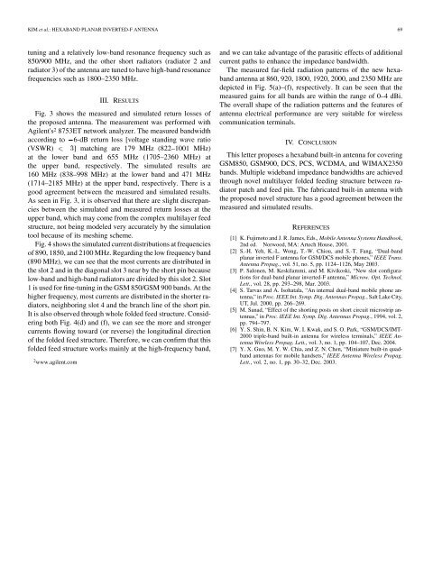
KIM et al.: HEXABAND PLANAR INVERTED-F ANTENNA 69tuning and a relatively low-band resonance frequency such as850/900 MHz, and the other short radiators (radiator 2 andradiator 3) of the antenna are tuned to have high-band resonancefrequencies such as 1800–2350 MHz.III. RESULTSFig. 3 shows the measured and simulated return losses ofthe proposed antenna. The measurement was per<strong>for</strong>med withAgilent's 2 8753ET network analyzer. The measured bandwidthaccording to 6-dB return loss [voltage standing wave ratio(VSWR) ] matching are 179 MHz (822–1001 MHz)at the lower band and 655 MHz (1705–2360 MHz) atthe upper band, respectively. The simulated results are160 MHz (838–998 MHz) at the lower band and 471 MHz(1714–2185 MHz) at the upper band, respectively. There is agood agreement between the measured and simulated results.As seen in Fig. 3, it is observed that there are slight discrepanciesbetween the simulated and measured return losses at theupper band, which may come from the complex multilayer feedstructure, not being modeled very accurately by the simulationtool because of its meshing scheme.Fig. 4 shows the simulated current distributions at frequenciesof 890, 1850, and 2100 MHz. Regarding the low frequency band(890 MHz), we can see that the most currents are distributed inthe slot 2 and in the diagonal slot 3 near by the short pin becauselow-band and high-band radiators are divided by this slot 2. Slot1 is used <strong>for</strong> fine-tuning in the GSM 850/GSM 900 bands. At thehigher frequency, most currents are distributed in the shorter radiators,neighboring slot 4 and the branch line of the short pin.It is also observed through whole folded feed structure. Consideringboth Fig. 4(d) and (f), we can see the more and strongercurrents flowing toward (or reverse) the longitudinal directionof the folded feed structure. There<strong>for</strong>e, we can confirm that thisfolded feed structure works mainly at the high-frequency band,2 www.agilent.comand we can take advantage of the parasitic effects of additionalcurrent paths to enhance the impedance bandwidth.The measured far-field radiation patterns of the new hexabandantenna at 860, 920, 1800, 1920, 2000, and 2350 MHz aredepicted in Fig. 5(a)–(f), respectively. It can be seen that themeasured gains <strong>for</strong> all bands are within the range of 0–4 dBi.The overall shape of the radiation patterns and the features ofantenna electrical per<strong>for</strong>mance are very suitable <strong>for</strong> wirelesscommunication terminals.IV. CONCLUSIONThis letter proposes a hexaband built-in antenna <strong>for</strong> coveringGSM850, GSM900, DCS, PCS, WCDMA, and WIMAX2350bands. Multiple wideband impedance bandwidths are achievedthrough novel multilayer folded feeding structure between radiatorpatch and feed pin. The fabricated built-in antenna withthe proposed novel structure has a good agreement between themeasured and simulated results.REFERENCES[1] K. Fujimoto and J. R. James, Eds., Mobile <strong>Antenna</strong> Systems Handbook,2nd ed. Norwood, MA: Artech House, 2001.[2] S.-H. Yeh, K.-L. Wong, T.-W. Chiou, and S.-T. Fang, “Dual-bandplanar inverted F antenna <strong>for</strong> GSM/DCS mobile phones,” IEEE Trans.<strong>Antenna</strong> Propag., vol. 51, no. 5, pp. 1124–1126, May 2003.[3] P. Salonen, M. Keskilammi, and M. Kivikoski, “New slot configurations<strong>for</strong> dual-band planar inverted-F antenna,” Microw. Opt. Technol.Lett., vol. 28, pp. 293–298, Mar. 2003.[4] S. Tarvas and A. Isohatala, “An internal dual-band mobile phone antenna,”in Proc. IEEE Int. Symp. Dig. <strong>Antenna</strong>s Propag., Salt Lake City,UT, Jul. 2000, pp. 266–269.[5] M. Sanad, “Effect of the shorting posts on short circuit microstrip antennas,”in Proc. IEEE Int. Symp. Dig. <strong>Antenna</strong>s Propag., 1994, vol. 2,pp. 794–797.[6] Y. S. Shin, B. N. Kim, W. I. Kwak, and S. O. Park, “GSM/DCS/IMT-2000 triple-band built-in antenna <strong>for</strong> wireless terminals,” IEEE <strong>Antenna</strong>Wireless Propag. Lett., vol. 3, no. 1, pp. 104–107, Dec. 2004.[7] Y. X. Guo, M. Y. W. Chia, and Z. N. Chen, “Miniature built-in quadbandantennas <strong>for</strong> mobile handsets,” IEEE <strong>Antenna</strong> Wireless Propag.Lett., vol. 2, no. 1, pp. 30–32, Dec. 2003.


