Dual-band internal antenna of PIFA type for mobile handsets and ...
Dual-band internal antenna of PIFA type for mobile handsets and ...
Dual-band internal antenna of PIFA type for mobile handsets and ...
- No tags were found...
Create successful ePaper yourself
Turn your PDF publications into a flip-book with our unique Google optimized e-Paper software.
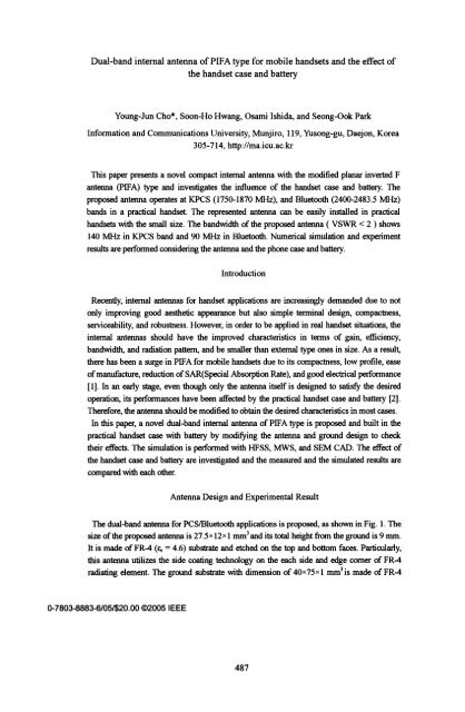
<strong>Dual</strong>-<strong>b<strong>and</strong></strong> <strong>internal</strong> <strong>antenna</strong> <strong>of</strong> <strong>PIFA</strong> <strong>type</strong> <strong>for</strong> <strong>mobile</strong> <strong>h<strong>and</strong>sets</strong> <strong>and</strong> the effect <strong>of</strong>the h<strong>and</strong>set case <strong>and</strong> batteryYoung-Jun Cho*, Soon-Ho Hwang, Osami Ishida, <strong>and</strong> Seong-Ook ParkIn<strong>for</strong>mation <strong>and</strong> Communications University, Munjiro, 119, Yusong-gu, Daejon, Korea305-714, http://ma.icu.ac.krThis paper presents a novel compact intemal <strong>antenna</strong> with the modified planar inverted F<strong>antenna</strong> (<strong>PIFA</strong>) <strong>type</strong> <strong>and</strong> investigates the influence <strong>of</strong> the h<strong>and</strong>set case <strong>and</strong> battery. Theproposed <strong>antenna</strong> operates at KPCS (1750-1870 MHz), <strong>and</strong> Bluetooth (2400-2483.5 MHz)<strong>b<strong>and</strong></strong>s in a practical h<strong>and</strong>set. The represented <strong>antenna</strong> can be easily installed in practical<strong>h<strong>and</strong>sets</strong> with the small size. The <strong>b<strong>and</strong></strong>width <strong>of</strong> the proposed <strong>antenna</strong> ( VSWR < 2 ) shows140 MH-lz in KPCS <strong>b<strong>and</strong></strong> <strong>and</strong> 90 MHlz in Bluetooth. Numerical simulation <strong>and</strong> experimentresults are per<strong>for</strong>med considering the <strong>antenna</strong> <strong>and</strong> the phone case <strong>and</strong> battery.IntroductionRecently, <strong>internal</strong> <strong>antenna</strong>s <strong>for</strong> h<strong>and</strong>set applications are increasingly dem<strong>and</strong>ed due to notonly improving good aesthetic appearance but also simple terminal design, compactness,serviceability, <strong>and</strong> robustness. However, in order to be applied in real h<strong>and</strong>set situations, theintemal <strong>antenna</strong>s should have the improved characteristics in terms <strong>of</strong> gain, efficiency,<strong>b<strong>and</strong></strong>width, <strong>and</strong> radiation pattem, <strong>and</strong> be smaller than extemal <strong>type</strong> ones in size. As a result,there has been a surge in <strong>PIFA</strong> <strong>for</strong> <strong>mobile</strong> <strong>h<strong>and</strong>sets</strong> due to its compactness, low pr<strong>of</strong>ile, ease<strong>of</strong> manufacture, reduction <strong>of</strong> SAR(Special Absorption Rate), <strong>and</strong> good electncal per<strong>for</strong>mance[1]. In an early stage, even though only the <strong>antenna</strong> itself is designed to satisfy the desiredoperation, its per<strong>for</strong>mances have been affected by the practical h<strong>and</strong>set case <strong>and</strong> battery [2].There<strong>for</strong>e, the <strong>antenna</strong> should be modified to obtain the desired characteristics in most cases.In this paper, a novel dual-<strong>b<strong>and</strong></strong> <strong>internal</strong> <strong>antenna</strong> <strong>of</strong> <strong>PIFA</strong> <strong>type</strong> is proposed <strong>and</strong> built in thepractical h<strong>and</strong>set case with battery by modifying the <strong>antenna</strong> <strong>and</strong> ground design to checktheir effects. The simulation is per<strong>for</strong>med with HFSS, MWS, <strong>and</strong> SEM CAD. The effect <strong>of</strong>the h<strong>and</strong>set case <strong>and</strong> battery are investigated <strong>and</strong> the measured <strong>and</strong> the simulated results arecompared with each other.Antenna Design <strong>and</strong> Experimental ResultThe dual-<strong>b<strong>and</strong></strong> <strong>antenna</strong> <strong>for</strong> PCS/Bluetooth applications is proposed, as shown in Fig. 1. Thesize <strong>of</strong> the proposed <strong>antenna</strong> is 27.5x 12X 1 mm3 <strong>and</strong> its total height from the ground is 9 mm.It is made <strong>of</strong> FR-4 (a, = 4.6) substrate <strong>and</strong> etched on the top <strong>and</strong> bottom faces. Particularly,this <strong>antenna</strong> utilizes the side coating technology on the each side <strong>and</strong> edge comer <strong>of</strong> FR-4radiating element. The ground substrate with dimension <strong>of</strong> 40x75x 1 mm3is made <strong>of</strong> FR-40-7803-8883-6/05/$20.00 @2005 IEEE487
<strong>and</strong> has via holes. The <strong>antenna</strong> fed by a 50 Ql coaxial cable has two radiating elements on thetop <strong>and</strong> bottom faces pomted at A <strong>and</strong> B, <strong>and</strong> a parasitic pait marked on C in Fig. 1. Due toutilizng both faces, the size <strong>of</strong> the <strong>antenna</strong> can be fuither reduced <strong>and</strong> each radiating patchhas more available room. Fig. 2 shows the measured <strong>and</strong> simulated return losses related withdifferent gap spaces. When the gap spaces are 0.5 mm, the <strong>antenna</strong> covers both the KPCS<strong>and</strong> Bluetooth <strong>b<strong>and</strong></strong>s in the measured result. The gap space has a greater effect on theBluetooth <strong>b<strong>and</strong></strong> than in KPCS <strong>b<strong>and</strong></strong> because the parasitic element <strong>of</strong> the bottom face isrelatively larger than the top one. As a result, the gap spaces have an effect on impedancematching <strong>and</strong> resonant frequency. Fig. 3 shows the surface current distributions <strong>and</strong> the trace<strong>of</strong> reflection coefficient on the Smith chart. As shown in Fig. 3 (a)-(d), the cunrentdistributions are dominant on the top face in KPCS <strong>and</strong> on the bottom face in the Bluetooth<strong>b<strong>and</strong></strong>, respectively The electrical length <strong>of</strong> each associated radiating element conresponds toquarter-wavelength (AV4) from the feed point to open end in Fig. 3 (a) <strong>and</strong> (d). Their lengthsare about 22 mm at 1.8 GHz <strong>and</strong> 14.5mm at 2.44 GHz. In Fig. 3, the measured points <strong>of</strong>1.8GHz <strong>and</strong> 2.44GHz are concentrated <strong>and</strong> the trace <strong>of</strong> KPCS <strong>and</strong> Bluetooth <strong>b<strong>and</strong></strong> are rolledin the center vicinity <strong>of</strong> the Smith chart. This means the <strong>antenna</strong> is well matched in eachdesired <strong>b<strong>and</strong></strong>. The measured <strong>and</strong> simulated radiation pattems at 1.8 GHz <strong>and</strong> 2.44 GHz areplotted together in Fig. 4 <strong>and</strong> show a good agreement with each other. In particular, Fig. 4 (b)<strong>and</strong> (e) show that the radiating E-field is less in the back side <strong>of</strong> the ground than in the frontone, wher the head is located. This means the proposed <strong>antenna</strong> has litfle effect on the head.The measured <strong>and</strong> simulated maximum radiation gain is 1.91 dBi <strong>and</strong> 1.84 dBi at 1.8GHz,<strong>and</strong> 1.21 dBi <strong>and</strong> 1.18 dBi at 2.44 GHz.Antenna Built In a H<strong>and</strong>set Case with Battery <strong>and</strong> Experimental ResultAfterdesigning the proposed <strong>antenna</strong>, in orderto install in practical h<strong>and</strong>set case, the shape <strong>and</strong>size <strong>of</strong> the <strong>antenna</strong> <strong>and</strong> grund are changed, as shown in Fig. 5 <strong>and</strong> the total height <strong>of</strong>the <strong>antenna</strong>is fixed to 7 mm. Fig. 6 shows themloss <strong>of</strong>the original proposed <strong>antenna</strong> built in the h<strong>and</strong>setcase with battery. The center fiequency <strong>of</strong>the KPCS <strong>b<strong>and</strong></strong> is shifted down about 200 MHz due tothe h<strong>and</strong>set case with battery, but the one <strong>of</strong> Bluetooth <strong>b<strong>and</strong></strong> is only slightly changed because theswbsates(*e4.6) <strong>of</strong> the <strong>antenna</strong> <strong>and</strong> ground affect the radiatng element <strong>of</strong> the bottom face morethan the h<strong>and</strong>set case(e,=2.8) due to the position <strong>of</strong> the bottom face. The configuration <strong>of</strong> themodified <strong>antenna</strong> is represented in Fig.5. The length <strong>of</strong> the radiaing elemnent <strong>of</strong> the top face isreduced from 26 mm to 22 mm <strong>and</strong> the vertical gap size is also reduced from 0.5 mm to 0.3 mm.The final result <strong>of</strong> the measurd <strong>and</strong> simulated retum loss is shown in Fig. 6. The <strong>b<strong>and</strong></strong>width(VSWR < 2) is 140 MHz (1740 - 1880 MHz) in KPCS <strong>b<strong>and</strong></strong> <strong>and</strong> 90 MHz (2400 - 2490 MHz) inBluetooth. Fig. 7 represents the gcometry <strong>of</strong> the h<strong>and</strong>set case with battery. The relafivepermittivity <strong>and</strong> conductivity <strong>of</strong>each material is presented in Table I. The h<strong>and</strong>set case is made <strong>of</strong>Acetal(er=2.8, Oa=0.002), one <strong>of</strong> the materials most commonly used <strong>for</strong> the commerial phonecase. The radiation pattems <strong>for</strong> the modified <strong>antenna</strong> in the h<strong>and</strong>set case with a batery are shownin Fig. 8. The rdiation pattes bwe those with <strong>and</strong> without are similar to each other. Theradiaig E-field is also less in the backside <strong>of</strong>the grud. The measured maximum radiation gain488
is 1.69 dBi at 1.8 GHz <strong>and</strong> 1.28 dBi at 2.44 GHz, respectivelyConclusionA novel <strong>antenna</strong> <strong>of</strong> <strong>PIFA</strong> <strong>type</strong> suitable <strong>for</strong> KPCS <strong>and</strong> Bluetooth <strong>b<strong>and</strong></strong>s has been proposed<strong>and</strong> experimentally studied. In addition, the <strong>antenna</strong> is applied to the practical h<strong>and</strong>set withbattery This paper presented the effects <strong>of</strong> the h<strong>and</strong>set case <strong>and</strong> battery on <strong>antenna</strong>per<strong>for</strong>mance. The characteristics <strong>of</strong> the proposed <strong>antenna</strong> are changed thiugh being built inthe h<strong>and</strong>set case, <strong>and</strong> the design <strong>of</strong>the original <strong>antenna</strong> is modified. These features make theproposed <strong>antenna</strong> attractive <strong>for</strong> <strong>mobile</strong> <strong>h<strong>and</strong>sets</strong>.AcknowledgementThis work is supported by National Research Laboratory (NRL) <strong>of</strong> Ministry <strong>of</strong> Science<strong>and</strong> Technology, Korea, uwder contract M1-0203-00-0015References:[I] L. Z. Do_g, P S. Hall, amid D. Wake, 'iXW-fiNticy planar ineed-F antnnas," IEEE Tnms.AnsvPN.agat.,vol.45,pp. 1451-1458,Oct 1997[2] D. U. Sin, S. 0. Park "The fl ccs<strong>of</strong>he h<strong>and</strong>setcase, batts<strong>and</strong>hunhadrntheperlmnanrce<strong>of</strong>atripe-<strong>b<strong>and</strong></strong> imlarkna,"An vwpagat,vol. 2,pp. 1951-1954, June 2004Fig I.Configuration <strong>of</strong> the proposed <strong>antenna</strong>r,Iq~~~~~~~........tFig. 2. The return loss(a) @ 1.8GHz (Top) (c) @- 2.44GHz (Top)(b)@ 1.8GHz (Bottom) (d) u 2.44GHz (Bottom) (e) Smith chartFig. 3. Surface current distributions <strong>and</strong> the trace <strong>of</strong> reflection coefficient(a) x-y plane_-1.8GHz (b) x-z plane @1.8GHz (c) y-z plane 1. 8GHz489
(d) x-y plane @2.44GHZ (e) x-z plane @2.44GHz (t) y-z plane @2.44GHzFig. 4. Radiation patterns <strong>for</strong> the proposed <strong>antenna</strong> at 1.8 GHz <strong>and</strong> 2.44 GHzPCSBluetloth:1~~~~~~~~ ~~~~~~ ..........m--s~~~~~~~~~~~~~~~~~~.. C:.S___Y...l.l..C........Fig. 5. Configuration <strong>of</strong> the modified <strong>antenna</strong>IGH..Fig. 6. The return loss_ ~ _ . Fre.TABLE Ia D _ _ Parameters <strong>of</strong> the Substrate,H<strong>and</strong>set case, <strong>and</strong> Battery103 s GE (S/M)_ ^ /3 FR-4 4.6Case 2.8 0.002'_J / f Battery 3.0 0.5Fig. 7. Geometry <strong>of</strong> the h<strong>and</strong>set case with battery(a) x-y plane @1.8GHz (b) x-z plane @1.8GHz (c) y-z plane @1.8GHz\/-(d) x-y plane @2.44GHz (e) x-z plane @2.44GHz (f) y-z plane @2.44GHzFig. 8. Radiation pattems <strong>for</strong> the modified <strong>antenna</strong> at 1.8 GHz <strong>and</strong> 2.44 GHz490


