

Dual-Band and Dual-Polarization Patch Antenna with High Isolation ...
Dual-Band and Dual-Polarization Patch Antenna with High Isolation ...
Dual-Band and Dual-Polarization Patch Antenna with High Isolation ...

You also want an ePaper? Increase the reach of your titles
YUMPU automatically turns print PDFs into web optimized ePapers that Google loves.
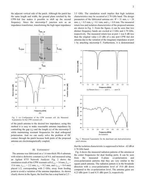
2the adjacent vertical side of the patch. Although the patch hasthe same length <strong>and</strong> width, the ground plane notched by theCPW-fed line makes it possible to shift up the secondfrequency. Since the microstrip-T junction acts as animpedance transformer, transforming the high input impedance3.5 GHz. The simulation result implies that high isolationcharacteristics may be occurred at 2.78 GHz b<strong>and</strong>. The designparameters of the fabricated antenna are: W = 31 mm, t l = 28mm, t w = 0.5 mm, t g = 0.1 mm, <strong>and</strong> c d = 0.8 mm. The measuredreturn loss <strong>and</strong> isolation characteristics of the proposed antennaare shown in Fig. 3. From the figure, it can be seen that twodistinct frequency b<strong>and</strong>s are excited at 2 GHz <strong>and</strong> 2.78 GHz,respectively. The measured return loss at port 1 was 8 dB lessthan the original value (-23 dB) of a one port CPW-fed slotantenna due to the variation of the imaginary impedance at port1 by attaching microstrip-T. Furthermore, it is demonstrated(a)(a) Return loss (——— port 1, – – – port 2)(b)Fig. 2. (a) Configuration of the CPW resonant cell. (b) MeasuredS-parameters for the CPW resonant cell.of the patch antenna to the desired low impedance, using thismethod it is easy to make reasonable antenna impedance bycontrolling the gap (t g ) <strong>and</strong> the length (t l ) of the microstrip-Twhile maintaining resonant frequencies for dual orthogonalpolarization. And we can easily solve the problem of DCcontact through the patch because both ports of the proposedantenna are electromagnetically coupled..III. EXPERIMENTThe antenna was fabricated on a 1.6 mm-thick FR-4 substrate<strong>with</strong> relative dielectric constant (ε r ) of 4.6, <strong>and</strong> measured usingan Agilent 8755 Network Analyzer. Fig. 2 shows thesimulation result of the CPW resonant cell (L cpw = 14 mm, L res =13.6 mm, t res_w = 2.2 mm, t res = 0.2 mm, <strong>and</strong> t res_g = 0.4 mm)placed λ/2, corresponding <strong>with</strong> 2 GHz, away from feedingpoint to avoid a variation of the antenna impedance. As shownclearly shown in the figure, the feed line has a stop b<strong>and</strong> at 2.5 –(b) <strong>Isolation</strong>Fig. 3. Measured S-parameter for the dual-b<strong>and</strong> <strong>and</strong> dual-polarizationpatch antennathat the isolation characteristic is suppressed to below –62 dB at2.78 GHz b<strong>and</strong>.Fig. 4 shows the measured radiation patterns of the antenna atthe center frequencies for dual feeding ports. It can be seenfrom the measured E-plane co-polarization <strong>and</strong>cross-polarization patterns that they are very similar to thesquare patch antenna. The radiation pattern is in the broadsidedirection <strong>with</strong> a cross-polarization level of 19.8 dB downcompared to the co-polarization level. The antenna gains are4.23 dBi (port 1) <strong>and</strong> 4.51 dBi (port 2), respectively.


