

A Broadband T-Shaped Microstrip-line-fed Slot Antenna with ...
A Broadband T-Shaped Microstrip-line-fed Slot Antenna with ...
A Broadband T-Shaped Microstrip-line-fed Slot Antenna with ...
- No tags were found...

You also want an ePaper? Increase the reach of your titles
YUMPU automatically turns print PDFs into web optimized ePapers that Google loves.
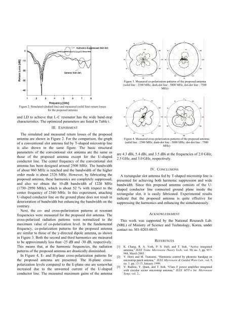
Figure 3. Measured co-polarization patterns of the proposed antenna(solid <strong>line</strong> : 2500 MHz, dash-dot <strong>line</strong> : 5000 MHz, dot-dot <strong>line</strong> : 7500MHz)Figure 2. Simulated (dashed <strong>line</strong>) and measured (solid <strong>line</strong>) return lossesfor the proposed antennaand LD to achieve that L-C resonator has the wide band-stopcharacteristics. The optimized parameters are listed in Table I.III. EXPERIMENTThe simulated and measured return losses of the proposedantenna are shown in Figure 2. For the comparison, the graphof a conventional slot antenna <strong>fed</strong> by T-shaped microstrip <strong>line</strong>is also shown in the same figure. The basic structuralparameters of the conventional slot antenna are the same asthose of the proposed antenna except for the U-shapedconductor <strong>line</strong>. The center frequency of the conventional slotantenna has been designed around 2500 MHz. The bandwidthof about 960 MHz is reached and the bandwidth of the higherorder mode is about 2326 MHz. However, by fabricating theproposed antenna, these harmonics are completely suppressed,and also we obtain the 10-dB bandwidth of 1220 MHz(1730~2950 MHz), which is about 52 % <strong>with</strong> respect to thecenter frequency of 2340 MHz. In this experiment, attachingU-shaped conductor <strong>line</strong> on the ground plane does not result indeterioration of bandwidth but enhancing the bandwidth on thecontrary.Next, the co- and cross-polarization patterns at resonantfrequencies were measured for the proposed slot antenna. Thecross-polarized radiation patterns were normalized to themaximum value of co-polarization level. In the fundamentalfrequency, co-polarization patterns for the proposed antennaare similar to those of the y-directed dipole antenna, as shownin Figure 3. Both the second and third harmonics are measuredto be approximately less than -25 dB and -30 dB, respectively.This means that, at the harmonic frequencies, the radiationpatterns of the proposed antenna are drastically diminished.In Figure 4, E- and H-plane cross-polarization patterns forthe proposed antenna are presented. The H-plane crosspolarizationlevels compared to the E-plane one are somewhatincreased due to the unwanted current of the U-shapedconductor <strong>line</strong>. The measured maximum gains of the antennaFigure 4. Measured cross-polarization patterns of the proposed antenna(solid <strong>line</strong> : 2500 MHz, dash-dot <strong>line</strong> : 5000 MHz, dot-dot <strong>line</strong> : 7500MHz)are 4.3 dBi, 5.4 dBi, and 3.5 dBi at the frequencies of 2.0 GHz,2.5 GHz, and 3.0 GHz, respectively.IV. CONCLUSIONSA rectangular slot antenna <strong>fed</strong> by T-shaped microstrip <strong>line</strong> ispresented for achieving both harmonic suppression and widebandwidth. Since this proposed antenna consists of the U-shaped conductor <strong>line</strong> connected ground plane inside therectangular slot, it is easily fabricated. Experimental resultsindicate that the proposed antenna is quite effective forsuppressing the harmonics and enhancing the simultaneously.ACKNOWLEDGMENTThis work was supported by the National Research Lab.(NRL) of Ministry of Science and Technology, Korea, undercontact no. M1-0203-0015.REFERENCES[1] K. Chang, R. A. York, P. S. Hall, and T. Itoh, “Active integratedantenna,” IEEE Trans. Microwave Theory Tech., vol. 50, no. 3, pp. 937-944, March 2003.[2] Y. Horii and M. Tsutusmi, “Harmonic control by photonic bandgap onmicrostrip patch antenna,” IEEE Microwave & Guided Wave Lett., vol. 9,no. 1. pp. 13-15, January 1999.[3] V. Radisic, Y. Quan, and T. Itoh, “Class F power amplifier integrated<strong>with</strong> circular sector microstrip antenna,” IEEE MTT-s Int. MicrowaveSymp. vol. 2,.


