Rev. 004 A BTR 185 - Quick® SpA
Rev. 004 A BTR 185 - Quick® SpA
Rev. 004 A BTR 185 - Quick® SpA

You also want an ePaper? Increase the reach of your titles
YUMPU automatically turns print PDFs into web optimized ePapers that Google loves.
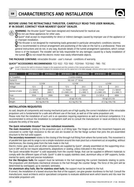
GBCHARACTERISTICS AND INSTALLATIONBEFORE USING THE RETRACTABLE THRUSTER, CAREFULLY READ THIS USER MANUAL.IF IN DOUBT, CONTACT YOUR NEAREST QUICK ® DEALER.WARNING: the thruster Quick ® have been designed and manufactured for nautical use.Do not use these appliances for other uses.Quick ® shall accept no responsibility for direct or indirect damages caused by improper use of the appliance oran improper installation.The thruster is not designed for maintaining loads generated in particular atmospheric conditions (storms).It is recommended to entrust arrangement and positioning of the tube on the hull to a professional. These aregeneral instructions and do not, in any way, illustrate details of the tunnel arrangement operations, which competenceis of the boatyard. The installer will be fully responsible for any damages caused by a faulty installation ofthe tunnel. Do not install the electric motor near easily inflammable objects.THE PACKAGE CONTAINS: retractable thruster - user's manual - conditions of warranty.QUICK ® ”ACCESSORIES RECOMMENDED: TCD 1022 - TCD 1042 - TCD1044 - TCD1062 - TMS - TSCFMODELS <strong>BTR</strong>1806512 <strong>BTR</strong>1806524 <strong>BTR</strong>1808512 <strong>BTR</strong>1808524 <strong>BTR</strong>1810512 <strong>BTR</strong>1810524N° Propellers 2 contra-rotatingTunnel Ø <strong>185</strong> mm (7” 18/64)Motor Power 3,0 KW 4,0 KW 6,0 KWVoltage 12 V 24 V 12 V 24 V 12 V 24 VSection of wire20Quick ® reserves the right to introduce changes to the equipment and the contents of this manual without prior notice.In case of discordance or errors in translation between the translated version and the original text in the Italian language, reference will be made to the Italian or English text.2 x 50mm 2(2 x AWG 1)50mm 2(AWG 1)2 x 70mm 2(2 x AWG 2/0)2 x 50mm 2(2 x AWG 1)2 x 95mm 2(2 x AWG 3/0)2 x 50mm 2(2 x AWG 1)Fuse 355A 200A 500A 355A 2 x 325 A 400AThrust 65 kgf (143,3 lb) 85 kgf (187,4 lb) 105 kgf (231,5 lb)Weight 38,5 kg (84,9 lb) 42,5 kg (93,7 lb) 47,5 kg (104,7 lb)INSTALLATION REQUISITESAs said, despite all components and moving mechanical parts are of high quality, the correct installation of the retractablepropulsion unit is fundamental for a safe and efficient use of the boat, as well as of the same propulsion unit.Please note that the installation of such unit is an operation requiring experience as well as technical competence. It isrecommended to entrust the installation to competent staff and to consult the manufacturer or naval architects to fullyevaluate the entity of the work.The Quick retractable thruster ® has two individual movements.The main movement, relating to the propulsion part, is of tilting type. The hinges on which the movement happens areconceived to confer high resistance to the set and are located on the flat flange surface that joins the pre-assembledstructure to the hull solid support.The secondary movement relates to the closing of the through-hull fitting from where the tunnel exits. This movement isof parallel link type and its range is not a simple revolution around the main pivot but a movement act at expelling, withoutinterferences, the closing plate from the hole made in the hull.Electric motor, gear, levers and all other components are supplied by Quick ® , already assembled on the supporting structurein GRP and do not require adjustments, adaptations or sealing, unless indicated in this manual.The Quick retractable thruster ® is sold separately from the counter flange, that can be supplied in different materials tocomply with the different types of hulls. Quick ® is able to supply stainless steel, aluminium alloy or GRP supports, fundamentalfor quick, solid and precise installation.For the fibreglass hulls the support must be laminate in the hull respecting the current Standards relating to joints.The propulsion unit distributes mechanical stresses to the hull through the counter flange. The force of the joint will bedetermined by overlapped, up to standard, laminates.For aluminium alloy hulls, like for stainless steel hulls, the support must be welded to the hull.If correct, the installation of a boxed structure like that of the support, can give greater sturdiness to the hull. Consult themanufacturer, naval architects and/or specialised companies to evaluate additional work which beams and ribs near theretractable propulsion unit.RETRACTABLE THRUSTER <strong>BTR</strong><strong>185</strong> DP - IT GB - REV<strong>004</strong>A