Rev. 004 A BTR 185 - Quick® SpA
Rev. 004 A BTR 185 - Quick® SpA
Rev. 004 A BTR 185 - Quick® SpA

Create successful ePaper yourself
Turn your PDF publications into a flip-book with our unique Google optimized e-Paper software.
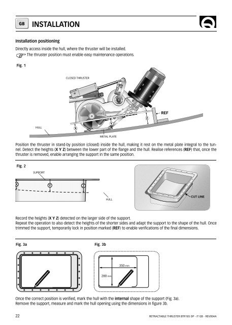
GBINSTALLATIONInstallation positioningDirectly access inside the hull, where the thruster will be installed.FThe thruster position must enable easy maintenance operations.Fig. 1CLOSED THRUSTERHULLX Y ZREFMETAL PLATEPosition the thruster in stand-by position (closed) inside the hull, making it rest on the metal plate integral to the tunnel.Detect the heights (X Y Z) between the lower part of the flange and the hull. Realise references (REF) that, once thethruster is removed, enable arranging the support in the same position.Fig. 2SUPPORTX Y ZHULLCUT LINERecord the heights (X Y Z) detected on the larger side of the support.Repeat the operation to also detect the heights of the shorter sides and adapt the support to the shape of the hull. Oncetrimmed the support, temporarily lock in position marked (REF) to enable verifications of the final dimensions.Fig. 3aFig. 3b350 mm280 mmOnce the correct position is verified, mark the hull with the internal shape of the support (Fig. 3a).Remove the support, measure and mark the hull opening using the dimensions in figure 3b.22RETRACTABLE THRUSTER <strong>BTR</strong><strong>185</strong> DP - IT GB - REV<strong>004</strong>A