i137 GEO binnen - GeoTechniek
i137 GEO binnen - GeoTechniek
i137 GEO binnen - GeoTechniek

Create successful ePaper yourself
Turn your PDF publications into a flip-book with our unique Google optimized e-Paper software.
DEFORMATION MONITORING OF THE UNDERGROUND METRO STATION ROTTERDAM CS<br />
the required measuring range of the measuring<br />
instrument;<br />
the required accuracy and frequency of measuring;<br />
the hazard warning levels;<br />
the way of communication.<br />
This paper will focus on the deformation monitoring<br />
of the metro station only. All other monitoring<br />
parameters are beyond the scope of this paper and<br />
will not be discussed.<br />
HAZARD WARNING LEVELS<br />
In order to make corrective actions effective, it is<br />
essential to compare the measured parameters with<br />
predefined hazard warning levels. These levels form<br />
an important part of the monitoring specifications<br />
(Berkelaar, 2006).<br />
The main criteria for the hazard warning levels were<br />
to assure the structural integrity of the station and<br />
safe operation of metro traffic. The structural<br />
engineers of RPW determined the levels based on the<br />
structural integrity whereas the RET provided<br />
specifications for safe metro operation. Two types of<br />
hazard warning levels were defined:<br />
the call or warning value; when exceeding this limit<br />
the contractor has to communicate this with RPW<br />
and take actions to prevent further exceeding of<br />
this value;<br />
the intervention value; when exceeding this limit<br />
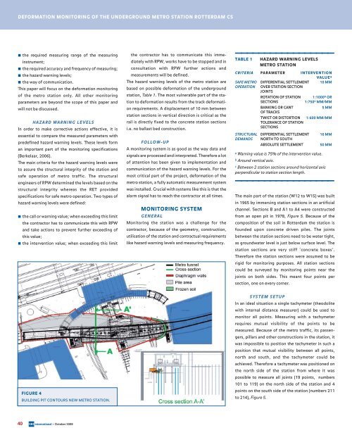
FIGURE 4<br />
BUILDING PIT CONTOURS NEW METRO STATION.<br />
40 <strong>GEO</strong>international – October 2008<br />
the contractor has to communicate this immediately<br />
with RPW, works have to be stopped and in<br />
consultation with RPW further actions and<br />
measurements will be defined.<br />
The hazard warning levels of the metro station are<br />
based on possible deformation of the underground<br />
station, Table 1. The most vulnerable part of the station<br />
to deformation results from the track deformation<br />
requirements. A displacement of 10 mm between<br />
station sections in vertical direction is critical as the<br />
rail is directly fixed to the concrete station sections<br />
i.e. no ballast bed construction.<br />
FOLLOW-UP<br />
A monitoring system is as good as the way data and<br />
signals are processed and interpreted. Therefore a lot<br />
of attention has been given to implementation and<br />
communication of the hazard warning levels. For the<br />
most critical part of the project, deformation of the<br />
metro station, a fully automatic measurement system<br />
was installed. Crucial with systems like this is that the<br />
alarm signal has to reach the contractor at all times.<br />
MONITORING SYSTEM<br />
GENERAL<br />
Monitoring the station was a challenge for the<br />
contractor, because of the geometry, construction,<br />
utilisation of the station and contractual requirements<br />
like hazard warning levels and measuring frequency.<br />
_________________<br />
TABLE 1 HAZARD WARNING LEVELS<br />
METRO STATION<br />
CRITERIA PARAMETER INTERVENTION<br />
VALUEa SAFE METRO DIFFERENTIAL SETTLEMENT 10 MM<br />
OPERATION OVER STATION SECTION<br />
JOINTS<br />
ROTATION OF STATION 1:1000b OR<br />
SECTIONS 1:750c MM/MM<br />
BANKING OR CANT<br />
OF TRACKS<br />
5 MM<br />
TWIST OR DISTORTION<br />
TOLERANCE OF STATION<br />
SECTIONS<br />
1:600 MM/MM<br />
STRUCTURAL DIFFERENTIAL SETTLEMENT 16 MM<br />
DEMANDS NORTH TO SOUTH<br />
ABSOLUTE SETTLEMENT 50 MM<br />
a Warning value is 75% of the intervention value.<br />
b Around vertical axis.<br />
c Between 2 station sections around horizontal axis<br />
perpendicular to station section length.<br />
_________________<br />
The main part of the station (W12 to W15) was built<br />
in 1965 by immersing station sections in an artificial<br />
channel. Sections B and A1 to A4 were constructed<br />
from an open pit in 1978, Figure 5. Because of the<br />
composition of the soil in Rotterdam the station is<br />
founded upon concrete driven piles. The joints<br />
between the station sections need to be water tight,<br />
as groundwater level is just below surface level. The<br />
station sections are very stiff ‘concrete boxes’.<br />
Therefore the station sections were assumed to be<br />
rigid for monitoring purposes. All station sections<br />
could be surveyed by monitoring points near the<br />
joints on both sides. This meant four points per<br />
section, one on every corner.<br />
SYSTEM SETUP<br />
In an ideal situation a single tachymeter (theodolite<br />
with internal distance measurer) could be used to<br />
monitor all points. Measuring with a tachymeter<br />
requires mutual visibility of the points to be<br />
measured. Because of the metro traffic, its passengers,<br />
pillars and other constructions in the station, it<br />
was impossible to position the tachymeter in such a<br />
position that mutual visibility between all points,<br />
north and south, and the tachymeter could be<br />
achieved. Therefore a tachymeter was positioned on<br />
the north side of the station from where it was<br />
possible to measure all joints (19 points, numbers<br />
101 to 119) on the north side of the station and 4<br />
points on the south side of the station (numbers 211<br />
to 214), Figure 5.