A.3. PRÉ-DIMENSIONAMENTO DE LAJES E PAREDES DE RESERVATÓRIOS JÁ LEVANDO EM CONTA A FISSURAÇÃO Tabela A11 - Pré-dimensionamento <strong>de</strong> Lajes e Pare<strong>de</strong>s <strong>de</strong> Reservatórios h (cm) C 25 com a c ≤0, 60 , CA-50A e 0, 300 ≤ ≤ 0, 450 ρ M (tf.m / m) φ e s (mm) (cm) A se (1) (cm 2 / m) A s e A s = r (cm2 / m) ( ) ρ % = A s d k6 (tf ; cm) 11,5 φ10,5 c/ 20 14,00 14,00 0,333 195,1 15,5 11,7 φ10,5 c/ 17,5 14,57 14,57 0,381 183,5 12,0 φ10,5 c/ 15 15,33 15,33 0,444 172,4 12,1 φ10,5 c/ 17,5 14,57 14,57 0,315 100,3 17,5 12,4 φ10,5 c/ 15 15,33 15,33 0,368 186,4 12,7 φ12,5 c/ 20 16,25 16,13 0,428 174,9 12,9 φ10,5 c/ 12,5 16,40 16,40 0,441 172,9 12,9 φ10,5 c/ 15 15,33 15,33 0,314 100,6 20,5 13,2 φ12,5 c/ 20 16,25 16,13 0,365 187,1 13,4 φ10,5 c/ 12,5 16,40 16,40 0,376 184,8 13,7 φ12,5 c/ 17,5 17,14 17,00 0,417 176,8 13,7 φ12,5 c/ 20 16,25 16,13 0,317 199,7 22,5 14,2 φ12,5 c/ 17,5 17,14 17,00 0,363 187,6 14,6 φ16,5 c/ 22,5 18,89 17,73 0,403 179,3 14,9 φ12,5 c/ 15 18,33 18,17 0,423 175,7 14,8 φ12,5 c/ 17,5 17,14 17,00 0,321 198,6 15,2 φ16,5 c/ 22,5 18,89 17,73 0,356 189,3 25,5 15,6 φ12,5 c/ 15 18,33 18,17 0,375 185,0 15,9 φ16,5 c/ 20 10,00 18,70 0,401 179,6 16,6 φ12,5 c/ 12,5 10,00 19,80 0,450 171,5 16,2 φ12,5 c/ 15 18,33 18,17 0,336 194,4 27,5 16,5 φ16,5 c/ 20 10,00 18,70 0,356 189,3 17,4 φ12,5 c/ 12,5 10,00 19,80 0,403 179,3 17,4 φ16,5 c/ 17,5 11,43 19,94 0,407 178,5 16,8 φ12,5 c/ 15 18,33 18,17 0,305 103,4 17,3 φ16,5 c/ 20 10,00 18,70 0,326 197,0 30,5 18,1 φ12,5 c/ 12,5 10,00 19,80 0,366 186,8 18,2 φ16,5 c/ 17,5 11,43 19,94 0,372 185,6 18,9 φ20,5 c/ 22,5 14,00 10,85 0,410 178,0 19,6 φ16,5 c/ 15 13,33 11,59 0,434 174,0 19,9 φ12,5 c/ 12,5 10,00 19,80 0,308 102,4 19,9 φ16,5 c/ 17,5 11,43 19,94 0,313 100,8 10,6 φ20,5 c/ 22,5 14,00 10,85 0,345 192,1 35,5 11,4 φ16,5 c/ 15 13,33 11,59 0,366 186,8 11,9 φ20,5 c/ 20 15,75 12,21 0,388 182,2 13,5 φ16,5 c/ 12,5 16,00 13,91 0,439 173,2 13,6 φ20,5 c/ 17,5 18,00 13,95 0,443 172,6 13,3 φ16,5 c/ 15 13,33 11,59 0,316 100,0 40,5 14,0 φ20,5 c/ 20 15,75 12,21 0,335 194,6 15,8 φ16,5 c/ 12,5 16,00 13,91 0,379 184,0 16,0 φ20,5 c/ 17,5 18,00 13,95 0,382 183,3 16,0 φ20,5 c/ 20 15,75 12,21 0,294 107,2 45,5 18,2 φ20,5 c/ 17,5 18,00 13,95 0,336 194,4 18,4 φ16,5 c/ 12,5 16,00 13,91 0,334 194,9 21,0 φ20,5 c/ 15 21,00 16,28 0,392 181,4 20,6 φ20,5 c/ 17,5 18,00 13,95 0,300 105,1 50,5 23,6 φ20,5 c/ 15 21,00 16,28 0,350 190,8 26,8 φ22,5 c/ 15 25,33 18,77 0,404 179,1 28,0 φ20,5 c/ 12,5 25,20 19,54 0,420 176,3 26,2 φ20,5 c/ 15 21,00 16,28 0,316 100,0 55,5 29,9 φ22,5 c/ 15 25,33 18,77 0,365 187,1 31,2 φ20,5 c/ 12,5 25,20 19,54 0,379 184,0 35,6 φ22,5 c/ 12,5 30,40 22,52 0,438 173,4 33,3 φ22,5 c/ 15 25,33 18,77 0,333 195,1 60,5 34,7 φ20, 5 c/ 12,5 25,20 19,54 0,346 191,8 39,7 φ22 ,5 c/ 12,5 30,40 22,52 0,399 180,0 43,0 φ20, 5 c/ 10 31,50 24,42 0,432 174,3 (1) A se (área efetiva) é a área <strong>de</strong> cálculo ( A s ) majo- φ ≤ 10 12,5 16 20 22 rada do coeficiente r para combater a fissuração. r 1 1,02 1,15 1,29 1,35 118
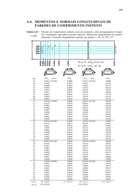
A.4. MOMENTOS E NORMAIS LONGITUDINAIS DE PAREDES DE COMPRIMENTO INFINITO Tabela A12 - Pare<strong>de</strong>s <strong>de</strong> comprimento infinito, inércia constante, com carregamentos triangu- ν = 0, 2 lar e retangular, apoiadas na borda superior. Momentos longitudinais nos pontos indicados e normais longitudinais apenas nos pontos 1, 10, 19, 28 e 37. M = p⋅ b2 ⋅coef ( tf. m / m) N = p⋅ b ⋅coef ( tf / m) i i i i Nós coef M i coef N coef M i coef M i coef N coef M i 01 -0,0291 (0,1920) 0,0000 -0,0751 (0,5520) 0,0000 02 -0,0104 0,0057 -0,0237 0,0152 03 0,0000 0,0082 0,0022 0,0212 04 0,0052 0,0089 0,0142 0,0224 05 0,0073 0,0086 0,0189 0,0216 06 0,0077 0,0072 0,0194 0,0184 07 0,0067 0,0061 0,0171 0,0159 08 0,0054 0,0053 0,0143 0,0139 09 0,0051 0,0051 0,0135 0,0135 10 -0,0346 (0,2380) 0,0000 -0,0812 (0,5760) 0,0000 11 -0,0118 0,0070 -0,0267 0,0164 12 0,0004 0,0099 0,0018 0,0230 13 0,0064 0,0105 0,0152 0,0244 14 0,0087 0,0100 0,0204 0,0233 15 0,0089 0,0083 0,0208 0,0195 16 0,0077 0,0070 0,0181 0,0166 17 0,0062 0,0061 0,0148 0,0144 18 0,0059 0,0059 0,0140 0,0140 19 -0,0368 (0,2660) 0,0000 -0,0786 (0,5520) 0,0000 20 -0,0118 0,0077 -0,0262 0,0161 21 0,0011 0,0106 0,0015 0,0224 22 0,0070 0,0109 0,0145 0,0234 23 0,0091 0,0102 0,0194 0,0220 24 0,0090 0,0083 0,0194 0,0180 25 0,0076 0,0070 0,0166 0,0151 26 0,0062 0,0060 0,0133 0,0129 27 0,0059 0,0059 0,0125 0,0125 28 -0,0349 (0,2700) 0,0000 -0,0679 (0,4820) 0,0000 29 -0,0102 0,0077 -0,0224 0,0143 30 0,0017 0,0100 0,0013 0,0192 31 0,0067 0,0099 0,0123 0,0195 32 0,0083 0,0090 0,0161 0,0179 33 0,0078 0,0070 0,0155 0,0139 34 0,0064 0,0058 0,0126 0,0113 35 0,0051 0,0050 0,0097 0,0094 36 0,0048 0,0048 0,0090 0,0090 37 -0,0286 (0,2400) 0,0000 -0,0504 (0,3640) 0,0000 38 -0,0074 0,0066 -0,0164 0,0110 39 0,0019 0,0079 0,0009 0,0137 40 0,0053 0,0073 0,0084 0,0129 41 0,0061 0,0062 0,0105 0,0111 42 0,0051 0,0044 0,0090 0,0075 43 0,0039 0,0034 0,0064 0,0053 44 0,0028 0,0027 0,0040 0,0038 45 0,0026 0,0026 0,0035 0,0035 M + max (B) 0,0095 (C) 0,0110 (A) 0,0215 (13) 0,0244 M - max (19) -0,0368 (10) -0,0812 M N 119
- Page 1 and 2:
PROJETOS ESTRUTURAIS DE RESERVATÓR
- Page 3 and 4:
SUMÁRIO LISTA DE FIGURAS..........
- Page 5 and 6:
c) Reservatórios achatados em fund
- Page 7 and 8:
ANEXO A............................
- Page 9 and 10:
Figura 2.15- Piscinas, tanques e ca
- Page 11 and 12:
Figura 3.12- Trecho principal de um
- Page 13 and 14:
Figura 3.35- Esquema estático do t
- Page 15 and 16:
Figura B.22- Estribo retangular com
- Page 17 and 18:
x LISTA DE TABELAS Tabela 2.10- Tip
- Page 19 and 20:
RESUMO COSTA, F. O. (1998). Projeto
- Page 21 and 22:
1 CAPÍTULO 1 INTRODUÇÃO O objeti
- Page 23 and 24:
contrados com um grau maior de difi
- Page 25 and 26:
CUBA.................. Parte formad
- Page 27 and 28:
Já quanto às lajes, dependendo da
- Page 29 and 30:
vazamentos do próprio reservatóri
- Page 31 and 32:
Figura 2.2 - Relação entre os des
- Page 33 and 34:
Figura 2.4 - Seção transversal de
- Page 35 and 36:
Obs.: 1º) Consideram-se como rígi
- Page 37 and 38:
estrutural que se está calculando
- Page 39 and 40:
4º) São dados nas figuras 2.10 a
- Page 41 and 42:
Figura 2.16 - Ábacos para o cálcu
- Page 43 and 44:
a) Fôrmas da laje do fundo de um r
- Page 45 and 46:
2ª ETAPA: Concretagem (vertical) d
- Page 47 and 48:
ase = 10,00 cm2 m (φ 10.0 c/ 8 com
- Page 49 and 50:
cubas deveriam ser feitas pelos pro
- Page 51 and 52:
Figura 2.18 - Reservatório de pres
- Page 53 and 54:
Figura 2.20 - Reservatório elevado
- Page 55 and 56:
2.4. CLASSIFICAÇÃO ESTRUTURAL E C
- Page 57 and 58:
Obs.: Como exceção a esta regra,
- Page 59 and 60:
• Cubas achatadas: são aquelas o
- Page 61 and 62:
de fôrmas sobre o segundo trecho c
- Page 63 and 64:
2º Processo: Torres de pilares, em
- Page 65 and 66:
2.4.6. Resumo das classificações
- Page 67 and 68:
47 CAPÍTULO 3 CONSIDERAÇÕES SOBR
- Page 69 and 70:
ação, como pela mesma razão é i
- Page 71 and 72:
Se se tomar como exemplo que a figu
- Page 73 and 74:
concreto armado igual 10 -5 por um
- Page 75 and 76:
TRINCAS II (Figura 3.3a) São trinc
- Page 77 and 78:
Figura 3.4 - Esquema estático simp
- Page 79 and 80:
Assim sendo, as paredes dos reserva
- Page 81 and 82:
3.2.2. Carregamentos dos reservató
- Page 83 and 84:
c) Reservatórios achatados em fund
- Page 85 and 86:
• Carregamento 2: Hipótese: rese
- Page 87 and 88: f) Reservatórios alongados sobre e
- Page 89 and 90: • Carregamento 2: Analogamente ao
- Page 91 and 92: • Carregamento 4: Hipótese: rese
- Page 93 and 94: • Carregamento 1: G + A Hipótese
- Page 95 and 96: • Carregamento 4: Hipótese: rese
- Page 97 and 98: a) Reservatórios elevados com fust
- Page 99 and 100: c) Reservatórios elevados com pila
- Page 101 and 102: • Carregamento 2: Hipótese: rese
- Page 103 and 104: ) Grupos estruturais Os reservatór
- Page 105 and 106: Reservatório em fundação direta
- Page 107 and 108: estão sendo preferidas, ou seja, a
- Page 109 and 110: As sapatas dos pilares devem ser r
- Page 111 and 112: Reservatórios em fundação direta
- Page 113 and 114: pilares e outras de 45 t , em torno
- Page 115 and 116: das entre elas por vigas. No caso d
- Page 117 and 118: vididas em um grande número de bar
- Page 119 and 120: 3.4. DIMENSIONAMENTO E DETALHAMENTO
- Page 121 and 122: ficações, como por exemplo a que
- Page 123 and 124: 103 ANEXO A Neste anexo apresentam-
- Page 125 and 126: TABELA A.2 - Momentos máximos: 4 q
- Page 127 and 128: TABELA A.4 - Momentos máximos: 4 q
- Page 129 and 130: k para M no engaste + k para M max
- Page 131 and 132: k para M max + k para M no k para M
- Page 133 and 134: Tabela A6 - Para dimensionamento no
- Page 135 and 136: Tabela A8 - Para dimensionamento no
- Page 137: Tabela A10 - Para dimensionamento n
- Page 141 and 142: Tabela A13 - Continuação... ν =
- Page 143 and 144: Figura B.1 - Casos comuns de estrib
- Page 145 and 146: B.1.1. ARMADURAS EXISTENTES E UTILI
- Page 147 and 148: superiores a 10 mm. Estribos com di
- Page 149 and 150: Assim sendo, ainda de acordo com os
- Page 151 and 152: o diâmetro φ' de barras mais exte
- Page 153 and 154: Deixando para os manuais das máqui
- Page 155 and 156: Estes dois tipos de gabaritos são
- Page 157 and 158: Aqui, os diâmetros dos pinos de do
- Page 159 and 160: Na hipótese de se fazer esse dobra
- Page 161 and 162: 1a etapa: gabd chave = 2, 5 cm e ga
- Page 163 and 164: Os ganchos são também representad
- Page 165 and 166: B.4.1. COMPRIMENTO DOS ESTRIBOS COM
- Page 167 and 168: ( ) 147 C = ∑ b' + ∑ h' + 2 3π
- Page 169 and 170: f) Estribos de um só ramo com ganc
- Page 171 and 172: B.4.2. COMPRIMENTOS DAS BARRAS DOBR
- Page 173 and 174: B.4.2.2. Fórmulas dos comprimentos
- Page 175 and 176: g) Barra sem gancho com uma dobra (
- Page 177 and 178: B.5. TABELAS AUXILIARES PARA CALCUL
- Page 179 and 180: 159
- Page 181 and 182: REFERÊNCIAS BIBLIOGRÁFICAS ASSOCI