removing the fc (forced convection) - This is a secure site - Whirlpool
removing the fc (forced convection) - This is a secure site - Whirlpool
removing the fc (forced convection) - This is a secure site - Whirlpool

You also want an ePaper? Increase the reach of your titles
YUMPU automatically turns print PDFs into web optimized ePapers that Google loves.
CONSUMER SERVICES TECHNICAL<br />
EDUCATION GROUP PRESENTS KM-29<br />
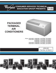
SPEEDCOOK<br />
MICROWAVE OVEN<br />
WITH CONVECTION<br />
<br />
JOB AID<br />
Part No. 8178545
FORWARD<br />
<strong>Th<strong>is</strong></strong> <strong>Whirlpool</strong> Job Aid, “Speedcook Microwave Oven With Convection” (Part No. 8178545), provides<br />
<strong>the</strong> technician with information on <strong>the</strong> installation, operation, and service of <strong>the</strong> Speedcook<br />
Microwave Oven With Convection. For specific information on <strong>the</strong> model being serviced, refer to<br />
<strong>the</strong> “Use and Care Guide,” or “Tech Sheet” provided with <strong>the</strong> Speedcook Microwave Oven With<br />
Convection.<br />
The Wiring Diagram and Strip Circuits used in th<strong>is</strong> Job Aid are typical and should be used for<br />
training purposes only. Always use <strong>the</strong> Wiring Diagram supplied with <strong>the</strong> product when servicing<br />
<strong>the</strong> unit.<br />
GOALS AND OBJECTIVES<br />
The goal of th<strong>is</strong> Job Aid <strong>is</strong> to provide information that will enable <strong>the</strong> service technician to properly<br />
diagnose malfunctions and repair <strong>the</strong> Speedcook Microwave Oven With Convection.<br />
The objectives of th<strong>is</strong> Job Aid are to:<br />
•<br />
•<br />
•<br />
•<br />
Understand and follow proper safety precautions.<br />
Successfully troubleshoot and diagnose malfunctions.<br />
Successfully perform necessary repairs.<br />
Successfully return <strong>the</strong> microwave oven to its proper operational status.<br />
WHIRLPOOL CORPORATION assumes no responsibility for any repairs<br />
made on our products by anyone o<strong>the</strong>r than Authorized Service Technicians.<br />
Copyright © 2006, <strong>Whirlpool</strong> Corporation, Benton Harbor, MI 49022<br />
- ii -
TABLE OF CONTENTS<br />
- iii -<br />
Page<br />
GENERAL . . . . . . . . . . . . . . . . . . . . . . . . . . . . . . . . . . . . . . . . . . . . . . . . . . . . . . . . . . . . . . 1-1<br />
Microwave Oven Safety . . . . . . . . . . . . . . . . . . . . . . . . . . . . . . . . . . . . . . . . . . . . . . . . . . 1-1<br />
Warning To Service Technicians . . . . . . . . . . . . . . . . . . . . . . . . . . . . . . . . . . . . . . . . . . . . 1-2<br />
Precautions To Be Observed Before And During Servicing To Avoid<br />
Possible Exposure To Excessive Microwave Energy . . . . . . . . . . . . . . . . . . . . . . . . . . 1-3<br />
RF Leakage Test . . . . . . . . . . . . . . . . . . . . . . . . . . . . . . . . . . . . . . . . . . . . . . . . . . . . . . . . 1-4<br />
Precautions To Be Observed While Troubleshooting . . . . . . . . . . . . . . . . . . . . . . . . . . . . 1-5<br />
<strong>Whirlpool</strong> Model & Serial Number Designations . . . . . . . . . . . . . . . . . . . . . . . . . . . . . . . . 1-6<br />
Model & Serial Number Label And Tech Sheet Locations . . . . . . . . . . . . . . . . . . . . . . . . . 1-7<br />
Specifications . . . . . . . . . . . . . . . . . . . . . . . . . . . . . . . . . . . . . . . . . . . . . . . . . . . . . . . . . . 1-8<br />
INSTALLATION INFORMATION . . . . . . . . . . . . . . . . . . . . . . . . . . . . . . . . . . . . . . . . . . . . . 2-1<br />
Installation Requirements . . . . . . . . . . . . . . . . . . . . . . . . . . . . . . . . . . . . . . . . . . . . . . . . . 2-1<br />
Installation Instructions . . . . . . . . . . . . . . . . . . . . . . . . . . . . . . . . . . . . . . . . . . . . . . . . . . . 2-3<br />
PRODUCT OPERATION . . . . . . . . . . . . . . . . . . . . . . . . . . . . . . . . . . . . . . . . . . . . . . . . . . . . 3-1<br />
Parts And Features . . . . . . . . . . . . . . . . . . . . . . . . . . . . . . . . . . . . . . . . . . . . . . . . . . . . . . 3-1<br />
Oven Control . . . . . . . . . . . . . . . . . . . . . . . . . . . . . . . . . . . . . . . . . . . . . . . . . . . . . . . . . . . 3-4<br />
Using The Quick Reference Guide . . . . . . . . . . . . . . . . . . . . . . . . . . . . . . . . . . . . . . . . . .3-11<br />
COMPONENT ACCESS . . . . . . . . . . . . . . . . . . . . . . . . . . . . . . . . . . . . . . . . . . . . . . . . . . 4-1<br />
Component Locations . . . . . . . . . . . . . . . . . . . . . . . . . . . . . . . . . . . . . . . . . . . . . . . . . . . . 4-1<br />
Removing The Bottom Cover . . . . . . . . . . . . . . . . . . . . . . . . . . . . . . . . . . . . . . . . . . . . . . 4-2<br />
Removing A Hood Lamp Socket, Base Thermostat, & Exhaust Fan Motor . . . . . . . . . . . . 4-3<br />
Removing The Turntable Motor & The Air Tube & Vent Base . . . . . . . . . . . . . . . . . . . . . . 4-5<br />
Removing The Relay Control Board And Line Fuse . . . . . . . . . . . . . . . . . . . . . . . . . . . . . 4-7<br />
Removing The Oven Door Components . . . . . . . . . . . . . . . . . . . . . . . . . . . . . . . . . . . . . 4-10<br />
Removing The Cavity Lamp And The Hood/Light Switch Board . . . . . . . . . . . . . . . . . . . 4-14<br />
Removing The Primary, Secondary, And Monitor Interlock Switches . . . . . . . . . . . . . . . 4-16<br />
Removing The Oven From The Installation . . . . . . . . . . . . . . . . . . . . . . . . . . . . . . . . . . . 4-17<br />
Removing The Cabinet . . . . . . . . . . . . . . . . . . . . . . . . . . . . . . . . . . . . . . . . . . . . . . . . . . 4-18<br />
Removing The FC (Forced Convection) Thermostat, The FC Motor,<br />
And The FC Ring Heater . . . . . . . . . . . . . . . . . . . . . . . . . . . . . . . . . . . . . . . . . . . . . . . 4-19<br />
Removing The FC Therm<strong>is</strong>tor, And The Cavity Thermostat<br />
& Humidity Sensor . . . . . . . . . . . . . . . . . . . . . . . . . . . . . . . . . . . . . . . . . . . . . . . . . . . . 4-22<br />
Removing The Grill Thermostat And Grill Elements . . . . . . . . . . . . . . . . . . . . . . . . . . . . 4-24<br />
Removing The Power Supply Cord And AC Line Filter . . . . . . . . . . . . . . . . . . . . . . . . . . 4-26<br />
Removing The FC (Forced Convection) Thermoactuator, The Magnetron<br />
Therm<strong>is</strong>tor, And The Magnetron . . . . . . . . . . . . . . . . . . . . . . . . . . . . . . . . . . . . . . . . . 4-27<br />
Removing The Waveguide Thermostat & Exhaust Fan Motor Capacitor . . . . . . . . . . . . 4-29<br />
Removing The Cooling Fan Motor . . . . . . . . . . . . . . . . . . . . . . . . . . . . . . . . . . . . . . . . . . 4-30<br />
Removing The Inverter Board . . . . . . . . . . . . . . . . . . . . . . . . . . . . . . . . . . . . . . . . . . . . . 4-31<br />
Removing The Relay Board . . . . . . . . . . . . . . . . . . . . . . . . . . . . . . . . . . . . . . . . . . . . . . 4-33
COMPONENT TESTING . . . . . . . . . . . . . . . . . . . . . . . . . . . . . . . . . . . . . . . . . . . . . . . . . . . 5-1<br />
Base Thermostat . . . . . . . . . . . . . . . . . . . . . . . . . . . . . . . . . . . . . . . . . . . . . . . . . . . . . . . . 5-1<br />
Exhaust Fan Motor . . . . . . . . . . . . . . . . . . . . . . . . . . . . . . . . . . . . . . . . . . . . . . . . . . . . . . 5-1<br />
Turntable Motor . . . . . . . . . . . . . . . . . . . . . . . . . . . . . . . . . . . . . . . . . . . . . . . . . . . . . . . . . 5-2<br />
Line Fuse . . . . . . . . . . . . . . . . . . . . . . . . . . . . . . . . . . . . . . . . . . . . . . . . . . . . . . . . . . . . . . 5-2<br />
Door Interlock Switches . . . . . . . . . . . . . . . . . . . . . . . . . . . . . . . . . . . . . . . . . . . . . . . . . . . 5-3<br />
FC Thermostat . . . . . . . . . . . . . . . . . . . . . . . . . . . . . . . . . . . . . . . . . . . . . . . . . . . . . . . . . . 5-3<br />
FC Motor . . . . . . . . . . . . . . . . . . . . . . . . . . . . . . . . . . . . . . . . . . . . . . . . . . . . . . . . . . . . . . 5-4<br />
FC Ring Heater . . . . . . . . . . . . . . . . . . . . . . . . . . . . . . . . . . . . . . . . . . . . . . . . . . . . . . . . . 5-4<br />
FC Therm<strong>is</strong>tor . . . . . . . . . . . . . . . . . . . . . . . . . . . . . . . . . . . . . . . . . . . . . . . . . . . . . . . . . . 5-5<br />
Cavity Thermostat & Humidity Sensor . . . . . . . . . . . . . . . . . . . . . . . . . . . . . . . . . . . . . . . . 5-5<br />
Grill Thermostat . . . . . . . . . . . . . . . . . . . . . . . . . . . . . . . . . . . . . . . . . . . . . . . . . . . . . . . . . 5-6<br />
Grill Elements . . . . . . . . . . . . . . . . . . . . . . . . . . . . . . . . . . . . . . . . . . . . . . . . . . . . . . . . . . 5-6<br />
FC Thermoactuator . . . . . . . . . . . . . . . . . . . . . . . . . . . . . . . . . . . . . . . . . . . . . . . . . . . . . . 5-7<br />
Magnetron Therm<strong>is</strong>tor . . . . . . . . . . . . . . . . . . . . . . . . . . . . . . . . . . . . . . . . . . . . . . . . . . . . 5-7<br />
Magnetron . . . . . . . . . . . . . . . . . . . . . . . . . . . . . . . . . . . . . . . . . . . . . . . . . . . . . . . . . . . . . 5-8<br />
Waveguide Thermostat . . . . . . . . . . . . . . . . . . . . . . . . . . . . . . . . . . . . . . . . . . . . . . . . . . . 5-8<br />
Exhaust Fan Motor Capacitor . . . . . . . . . . . . . . . . . . . . . . . . . . . . . . . . . . . . . . . . . . . . . . 5-9<br />
Cooling Fan Motor . . . . . . . . . . . . . . . . . . . . . . . . . . . . . . . . . . . . . . . . . . . . . . . . . . . . . . . 5-9<br />
DIAGNOSTICS & TROUBLESHOOTING . . . . . . . . . . . . . . . . . . . . . . . . . . . . . . . . . . . . . . 6-1<br />
Primary, Secondary, And Monitor Interlock Switch Checkout Procedure . . . . . . . . . . . . . 6-1<br />
Troubleshooting Circuit Test Chart . . . . . . . . . . . . . . . . . . . . . . . . . . . . . . . . . . . . . . . . . . 6-2<br />
Touch Panel And Relay Control Board Tests . . . . . . . . . . . . . . . . . . . . . . . . . . . . . . . . . . . 6-2<br />
Microwave Oven Power Output Test . . . . . . . . . . . . . . . . . . . . . . . . . . . . . . . . . . . . . . . . . 6-3<br />
Checking The Inverter . . . . . . . . . . . . . . . . . . . . . . . . . . . . . . . . . . . . . . . . . . . . . . . . . . . . 6-5<br />
WIRING DIAGRAM & STRIP CIRCUITS . . . . . . . . . . . . . . . . . . . . . . . . . . . . . . . . . . . . . . . 7-1<br />
Schematic Diagram . . . . . . . . . . . . . . . . . . . . . . . . . . . . . . . . . . . . . . . . . . . . . . . . . . . . . . 7-1<br />
Strip Circuits . . . . . . . . . . . . . . . . . . . . . . . . . . . . . . . . . . . . . . . . . . . . . . . . . . . . . . . . . . . 7-2<br />
TECH TIPS . . . . . . . . . . . . . . . . . . . . . . . . . . . . . . . . . . . . . . . . . . . . . . . . . . . . . . . . . . . . . . 8-1<br />
Grill Cooking Options . . . . . . . . . . . . . . . . . . . . . . . . . . . . . . . . . . . . . . . . . . . . . . . . . . . . 8-1<br />
High Voltage Inverter Power Supply Test . . . . . . . . . . . . . . . . . . . . . . . . . . . . . . . . . . . . . 8-4<br />
- iv -<br />
Page
GENERAL<br />
MICROWAVE OVEN SAFETY<br />
Your safety and <strong>the</strong> safety of o<strong>the</strong>rs <strong>is</strong> very important.<br />
We have provided many important safety messages in th<strong>is</strong> Job Aid and on <strong>the</strong> appliance.<br />
Always read and obey all safety messages.<br />
<strong>Th<strong>is</strong></strong> <strong>is</strong> <strong>the</strong> safety alert symbol.<br />
<strong>Th<strong>is</strong></strong> symbol alerts you to potential hazards that can kill or hurt you and o<strong>the</strong>rs.<br />
All safety messages will follow <strong>the</strong> safety alert symbol and ei<strong>the</strong>r <strong>the</strong> word<br />
“DANGER” or “WARNING.” These words mean:<br />
DANGER<br />
You can be killed or seriously injured if you don’t<br />
immediately follow instructions.<br />
You can be killed or seriously injured if you don’t<br />
follow instructions.<br />
All safety messages will tell you what <strong>the</strong> potential hazard <strong>is</strong>, tell you how to reduce <strong>the</strong> chance<br />
of injury, and tell you what can happen if <strong>the</strong> instructions are not followed.<br />
1-1
WARNING TO SERVICE TECHNICIANS<br />
To avoid possible exposure to microwave<br />
radiation or energy, v<strong>is</strong>ually check <strong>the</strong> oven<br />
for damage to <strong>the</strong> door and door seal before<br />
operating any oven. Use a microwave survey<br />
meter to check <strong>the</strong> amount of leakage before<br />
servicing. In <strong>the</strong> event <strong>the</strong> R.F. Ieakage<br />
exceeds 4 mw/cm2 at 5 cm, appropriate repair<br />
must be made before continuing to service <strong>the</strong><br />
unit. Check interlock function by operating <strong>the</strong><br />
door latch. The oven cook cycle should cut off<br />
before <strong>the</strong> door can be opened.<br />
The door and latching assembly contains <strong>the</strong><br />
radio frequency energy within <strong>the</strong> oven. The<br />
door <strong>is</strong> protected by three safety interlock<br />
switches. Do not attempt to defeat <strong>the</strong>m.<br />
Under no circumstances should you try to<br />
operate <strong>the</strong> oven with <strong>the</strong> door open.<br />
• Proper operation of microwave ovens<br />
requires that <strong>the</strong> magnetron be properly<br />
assembled to <strong>the</strong> waveguide and cavity.<br />
Never operate <strong>the</strong> magnetron unless it <strong>is</strong><br />
properly installed.<br />
• Be sure <strong>the</strong> “RF” seal <strong>is</strong> not damaged<br />
and <strong>is</strong> assembled around <strong>the</strong> magnetron<br />
dome properly when installing <strong>the</strong><br />
magnetron.<br />
• Routine service safety procedures<br />
should be exerc<strong>is</strong>ed at all times.<br />
• Untrained personnel should not attempt<br />
service without a thorough review of<br />
test procedures and safety information<br />
contained in th<strong>is</strong> Job Aid.<br />
1-2<br />
<strong>Whirlpool</strong> microwave ovens have a monitoring<br />
system designed to assure proper operation<br />
of <strong>the</strong> safety interlock systems.<br />
The monitor switch will immediately cause <strong>the</strong><br />
oven fuse to blow if <strong>the</strong> door <strong>is</strong> opened and<br />
<strong>the</strong> primary door interlock switch and/or <strong>the</strong><br />
secondary interlock switch contacts fail in a<br />
closed position.<br />
CAUTION: Replace a blown fuse with a 20<br />
ampere class H fuse only.<br />
Test <strong>the</strong> upper and lower door interlock<br />
switches, cook relay, and monitor switch<br />
(middle switch) for proper operation as<br />
described in <strong>the</strong> component test procedures,<br />
before replacing <strong>the</strong> blown oven fuse.<br />
Do not attempt to repair sticking contacts<br />
of any interlock switch, safety switch, or<br />
Cook (Latch) relay. The components must<br />
be replaced.<br />
Any indication of sticking contacts during<br />
component tests requires replacement of that<br />
component to assure reliability of <strong>the</strong> safety<br />
interlock system.<br />
If <strong>the</strong> fuse <strong>is</strong> blown, <strong>the</strong> Monitor switch,<br />
and <strong>the</strong> Primary, and Secondary interlock<br />
switches must be replaced. Be sure <strong>the</strong>y<br />
are properly connected.
PRECAUTIONS TO BE OBSERVED BEFORE AND DURING<br />
SERVICING TO AVOID POSSIBLE EXPOSURE<br />
TO EXCESSIVE MICROWAVE ENERGY<br />
A. Do not operate or allow <strong>the</strong> oven to be<br />
operated with <strong>the</strong> door open.<br />
B. Make <strong>the</strong> following safety checks on all<br />
ovens to be serviced before activating <strong>the</strong><br />
magnetron or o<strong>the</strong>r microwave source, and<br />
make repairs as necessary:<br />
•<br />
•<br />
•<br />
•<br />
•<br />
Interlock Operation<br />
Proper Door Closing<br />
Seal and Sealing Surfaces (Arcing,<br />
Wear, and O<strong>the</strong>r Damage)<br />
Damage to or Loosening of Hinges and<br />
Latches<br />
Evidence of Dropping or Abuse<br />
1-3<br />
C. Before turning on <strong>the</strong> microwave power<br />
for any service test or inspection within <strong>the</strong><br />
microwave generating components, check<br />
<strong>the</strong> magnetron, waveguide or transm<strong>is</strong>sion<br />
line, and cavity for proper alignment,<br />
integrity, and connections.<br />
D. Any defective or m<strong>is</strong>adjusted components<br />
in <strong>the</strong> interlock, monitor, door seal, and<br />
microwave generation and transm<strong>is</strong>sion<br />
systems shall be repaired, replaced, or<br />
adjusted, using procedures described in<br />
th<strong>is</strong> Job Aid, before <strong>the</strong> oven <strong>is</strong> released<br />
to <strong>the</strong> owner.<br />
E. A microwave leakage check to verify<br />
compliance with Federal Performance<br />
Standard should be performed on each<br />
oven prior to release to <strong>the</strong> owner.<br />
F. Do not attempt to operate <strong>the</strong> oven if <strong>the</strong><br />
door glass <strong>is</strong> broken.
EQUIPMENT<br />
Electromagnetic energy leakage monitor<br />
(NARDA 8100B, HOLADAY H 1501 ).<br />
275 ±15 ML glass beaker.<br />
TEST<br />
On every service call, checks for microwave<br />
energy em<strong>is</strong>sion must be made according to<br />
<strong>the</strong> following manner.<br />
1. Remove <strong>the</strong> cooking rack from <strong>the</strong><br />
oven cavity, if <strong>the</strong> microwave oven <strong>is</strong> so<br />
equipped.<br />
2. Place a 275 ±15 ML (9.3 oz.) glass of water<br />
in <strong>the</strong> center of <strong>the</strong> oven bottom.<br />
3. Select “HIGH” cook power, turn <strong>the</strong> microwave<br />
oven on, and test for R.F. Ieakage<br />
at <strong>the</strong> following locations:<br />
•<br />
•<br />
•<br />
•<br />
•<br />
•<br />
•<br />
•<br />
•<br />
•<br />
•<br />
•<br />
Around <strong>the</strong> cabinet at <strong>the</strong> front.<br />
Around <strong>the</strong> door.<br />
Across <strong>the</strong> console panel.<br />
Horizontally across <strong>the</strong> door.<br />
Vertically across <strong>the</strong> door.<br />
Diagonally across <strong>the</strong> door.<br />
Across <strong>the</strong> air vents.<br />
Across <strong>the</strong> rear air vent.<br />
All lockseams.<br />
Weld at bottom.<br />
Bottom plate.<br />
Oven feet.<br />
4. The scan speed <strong>is</strong> one inch per second.<br />
When checking for R.F. Ieakage, use an<br />
approved R.F. measuring device to assure<br />
less than 4 mw/cm 2 em<strong>is</strong>sion at 5 cm d<strong>is</strong>tance<br />
with a maximum scan rate of 2.54<br />
cm/second, in compliance with U.S. Government<br />
Department of Health, Education<br />
and Welfare 21CFR1030, Performance<br />
Standard for Microwave Ovens.<br />
A properly operating door and seal assembly<br />
will normally reg<strong>is</strong>ter small em<strong>is</strong>sions,<br />
but <strong>the</strong>y must be no greater than 4 mw/cm 2<br />
to allow for measurement uncertainty.<br />
RF LEAKAGE TEST<br />
1-4<br />
NOTE: Enter leakage readings in space BE-<br />
FORE and AFTER on <strong>the</strong> service document.<br />
All microwave ovens exceeding <strong>the</strong> em<strong>is</strong>sion<br />
level of 4 mw/cm2 must be reported to Dept.<br />
of Service for Microwave Ovens immediately<br />
and <strong>the</strong> owner should be told not to use <strong>the</strong><br />
microwave oven until it has been repaired<br />
completely.<br />
If a microwave oven <strong>is</strong> found to operate with<br />
<strong>the</strong> door open, report to Dept. of Service, <strong>the</strong><br />
manufacturer and CDRH* immediately. Also<br />
tell <strong>the</strong> owner not to use <strong>the</strong> oven.<br />
The monitor switch acts as <strong>the</strong> final safety<br />
switch protecting <strong>the</strong> customer from microwave<br />
radiation. If <strong>the</strong> monitor switch operated to blow<br />
<strong>the</strong> fuse when <strong>the</strong> interlocks failed, you must<br />
replace all interlock switches with new ones,<br />
because <strong>the</strong> contacts of those interlock switches<br />
may be melted and welded toge<strong>the</strong>r.<br />
If safety interlock/monitor switch replacement,<br />
or adjustment, <strong>is</strong> required, you must reconnect<br />
<strong>the</strong> circuit, and perform a continuity check on<br />
<strong>the</strong> monitor circuit.<br />
All repairs must be performed in such a manner<br />
that microwave energy em<strong>is</strong>sions are<br />
minimal.<br />
Address for CDRH <strong>is</strong>:<br />
Office of Compliance (HFZ-312) Center for<br />
Devices and Radiological Health<br />
1390 Piccard Drive<br />
Rockville, MD 20850<br />
* CDRH: Center for Devices and Radiological Health,<br />
Food and Drug Admin<strong>is</strong>tration.
PRECAUTIONS TO BE OBSERVED WHILE TROUBLESHOOTING<br />
The microwave oven <strong>is</strong> a high voltage, high<br />
current appliance. It <strong>is</strong> free from danger during<br />
ordinary use, but extreme care should be<br />
taken during repair.<br />
CAUTION<br />
Service technicians should remove <strong>the</strong>ir<br />
watches whenever working close to or replacing<br />
<strong>the</strong> magnetron.<br />
DANGER<br />
HIGH VOLTAGE AND HIGH TEMPERA-<br />
TURE (HOT/LIVE) OF THE INVERTER<br />
POWER SUPPLY<br />
The high voltage inverter power supply circuit<br />
supplies very high voltage and very high<br />
current for <strong>the</strong> magnetron tube. Though it <strong>is</strong><br />
free from danger in ordinary use, extreme<br />
care should be taken during repair. The<br />
current <strong>is</strong> extremely large, and so danger<br />
ex<strong>is</strong>ts because of its high current and high<br />
voltages.<br />
The aluminum heat sink <strong>is</strong> also energized<br />
with high voltage (HOT), so do not touch it<br />
when <strong>the</strong> AC input terminal <strong>is</strong> connected to<br />
<strong>the</strong> power line. One of <strong>the</strong> IGBT switching<br />
power devices (collector) <strong>is</strong> directly connected<br />
to <strong>the</strong> aluminum heat sink.<br />
The aluminum heat sink may be HOT from<br />
heat energy; <strong>the</strong>refore, extreme care should<br />
be taken during servicing and replacing.<br />
WARNING<br />
INVERTER POWER<br />
SUPPLY GROUNDING<br />
Check <strong>the</strong> high voltage inverter power supply<br />
circuit grounding. <strong>Th<strong>is</strong></strong> high voltage inverter<br />
power supply circuit board must have a proper<br />
chass<strong>is</strong> ground by <strong>the</strong> grounding bracket<br />
to <strong>the</strong> chass<strong>is</strong> ground; o<strong>the</strong>rw<strong>is</strong>e, th<strong>is</strong> H.V.<br />
inverter circuit board will expose very high<br />
voltage, and cause extreme DANGER. Be<br />
sure to have proper grounding by <strong>the</strong> grounding<br />
plate and screws.<br />
1-5<br />
WARNING<br />
DISCHARGING HIGH<br />
VOLTAGE CAPACITORS<br />
For about 30 seconds after <strong>the</strong> oven <strong>is</strong><br />
turned off, an electric charge remains in <strong>the</strong><br />
high voltage capacitors in <strong>the</strong> inverter power<br />
supply circuit board.<br />
When replacing or checking parts, remove<br />
<strong>the</strong> power plug from <strong>the</strong> outlet. Use a screwdriver<br />
with an insulated handle, and short<br />
<strong>the</strong> inverter output of <strong>the</strong> magnetron filament<br />
terminals to d<strong>is</strong>charge it. Be sure to touch<br />
<strong>the</strong> chass<strong>is</strong> ground side first, and <strong>the</strong>n touch<br />
<strong>the</strong> output terminals.<br />
WARNING<br />
There <strong>is</strong> high voltage present, with high current<br />
capabilities in <strong>the</strong> circuits of <strong>the</strong> primary<br />
and secondary windings, <strong>the</strong> choke coil, and<br />
<strong>the</strong> heat sink of <strong>the</strong> inverter. It <strong>is</strong> extremely<br />
dangerous to work on or near <strong>the</strong>se circuits<br />
with <strong>the</strong> microwave oven energized. DO<br />
NOT measure <strong>the</strong> voltage in <strong>the</strong> high voltage<br />
circuit, including <strong>the</strong> filament voltage of<br />
<strong>the</strong> magnetron.<br />
WARNING<br />
Never touch any circuit wiring with your hand,<br />
or with an insulated tool during operation.<br />
WARNING<br />
Never insert a wire, nail, or any o<strong>the</strong>r metal<br />
object through <strong>the</strong> lamp holes on <strong>the</strong> cavity,<br />
or any o<strong>the</strong>r holes or gaps. Doing so may<br />
act as an antenna, and cause microwave<br />
leakage.<br />
WARNING<br />
Before touching any oven components or<br />
wiring, always unplug <strong>the</strong> oven from its power<br />
source, and d<strong>is</strong>charge <strong>the</strong> capacitors in <strong>the</strong><br />
high voltage inverter.
WHIRLPOOL MODEL & SERIAL NUMBER DESIGNATIONS<br />
MODEL NUMBER<br />
MODEL NUMBER G H 7 20 8 X R T 0<br />
PRODUCT GROUP<br />
G = WHIRLPOOL GOLD<br />
M = MICROWAVE<br />
PRODUCT IDENTIFICATION<br />
B = BROWNER<br />
C = CONVECTION<br />
G = GRILL / CRISPER<br />
H = OTR HOOD COMBO<br />
K = KITS<br />
M = GOLD CONVECTION<br />
S = STIRRER FAN<br />
T = TURNTABLE<br />
MODEL VARIATIONS<br />
0 - 9<br />
CUBIC FEET<br />
20 = 2.0 CU. FT.<br />
22 = 2.2 CU. FT.<br />
FEATURE LEVEL<br />
8 = 28˝ KIT (IF KIT)<br />
FEATURE CODE<br />
C = CSA APPROVED<br />
S = CARRY IN WARRANTY (EFFECTIVE 02/96)<br />
X = IN HOME WARRANTY (EFFECTIVE O2/96)<br />
YEAR OF INTRODUCTION<br />
R = 2005<br />
COLOR CODE<br />
B = BLACK, Q = WHITE ON WHITE, T = BISCUIT, Y = GREY, S = STAINLESS STEEL<br />
ENGINEERING CHANGE (0, 1, 2, ETC.)<br />
SERIAL NUMBER<br />
SERIAL NUMBER TR S 24 10018<br />
MANUFACTURING SITE<br />
TR = OXFORD, MS; SHUNDE, CHINA<br />
YEAR OF PRODUCTION<br />
S = 2005<br />
WEEK OF PRODUCTION<br />
24TH WEEK<br />
PRODUCT SEQUENCE NUMBER<br />
1-6
MODEL & SERIAL NUMBER LABEL<br />
AND TECH SHEET LOCATIONS<br />
The Model/Serial Number label and Tech Sheet locations are shown below.<br />
Model/Serial Number Label<br />
1-7<br />
Tech Sheet (Behind<br />
Decorative Panel)
SPECIFICATIONS<br />
MODEL GH6208XRQ/B/S<br />
Model Description <strong>Whirlpool</strong> Speed Oven in White, Black, Stainless<br />
CONTROL SYSTEM<br />
Timer: Yes<br />
Type Electronic<br />
Limits 90 Min. 00 Sec.<br />
Scale Linear (Digital)<br />
Operation Touch Screen LCD Touch Pad Glass<br />
Keypad D<strong>is</strong>able / Child Lockout Mode Yes - Cancel Button<br />
Exhaust Fan: Yes - ON/OFF<br />
Number of Speeds 5-0FF + 4 steps Separate Button<br />
Automatic Turn On Temp 60oC, 140oF Cooktop Light Halogen<br />
Settings: 0FF + low-medium-high<br />
Night Light Yes - Separate Button<br />
Wattage 2 x 10 Watts<br />
Power Failure Indication Yes<br />
Invalid Data Entry 3 Short Beeps and Indication on D<strong>is</strong>play<br />
Technical Error Indication Pop-Up Screen “F-” With Error Number and Symbol + Call for Service<br />
Diagnostic System Yes<br />
Independent Minute Timer<br />
OVEN INTERIOR FEATURES<br />
Yes - 4 rapid very short tones<br />
Capacity 2.0 Cubic Feet<br />
Fin<strong>is</strong>h Non Stick Coating<br />
MW Cooking Power 1200 Watts (IEC-705 Rating)<br />
Grill Power 1500 Watts<br />
Turntable Yes - 16" Diameter<br />
Ventilation Radial blower<br />
Cooling Fan Automatic - On if oven <strong>is</strong> operating, off if door open<br />
Interior Light Halogen<br />
Automatic with soft On/Off - Turns on when oven door <strong>is</strong> open or oven <strong>is</strong><br />
Operation<br />
operating. Stays on after cooking cycle ended until door has been opened/<br />
closed or Cancel pressed<br />
Wattage 1 x 10 Watts<br />
1-8
MODEL GH6208XRQ/B/S<br />
DOOR FEATURES<br />
Stamped Steel Yes<br />
Window Curved Glass<br />
Seals Two Stage - (Capacitive and Reflective)<br />
MICROWAVE/GRILL SYSTEM<br />
D<strong>is</strong>tribution Top Feed w/o Stirrer<br />
Magnetron One - Inverter type<br />
Grill Halogen/Quartz<br />
SAFETY FEATURES<br />
Interlock Three Door/Latch Operated, Primary, secondary, and monitor<br />
Thermal Protectors Five - Magnetron, Oven Cavity, Hood, Grill, Waveguide<br />
VENTILATION SYSTEM<br />
Type Convertible Recirculation, Exhaust Vertical/Horizontal<br />
Duct Outlet Size 3-1/4" H x 10" W<br />
Recirculation CFM Out @ each Speed 200<br />
Exhaust CFM Out @each Speed 300<br />
No<strong>is</strong>e Level Recirculation 67dBA<br />
Damper Yes<br />
Odor Removal filter Yes - (2) Standard Charcoal<br />
Grease Filter Yes - (2) D<strong>is</strong>hwasher Safe<br />
Blower Type Radial<br />
Shipped Recirculation mode<br />
EXTERIOR FEATURES<br />
Cooktop Light w/Touch Control 2 Halogen Lamps - 10 Watts - Easy Access-Separate Button<br />
Power Cord Length 3 Feet<br />
OTHER SPECIFICATIONS<br />
Electrical 120V, Single Phase, 60 Hz, 1800 Watts, For Use With 15 - 20 Amp Circuit<br />
Domestic Use Only Yes<br />
Agency Approvals FCC, CDRH, UL, CUL<br />
APPROVED ACCESSORIES<br />
Exhaust Damper Assembly Yes (1 Set)<br />
Hardware for Installation Yes (1 Set)<br />
LITERATURE<br />
Use & Care Guide Part No. 8205283<br />
Installation Instructions Part No. 8205272<br />
Warranty In Use & Care Guide<br />
Tech Sheet Part No. 8205285<br />
Job Aid/Service Manual Part No. 8178545<br />
1-9
MODEL GH7208XRQ/B/T/S/Y<br />
Model Description <strong>Whirlpool</strong> Speed Oven with Convection<br />
CONTROL SYSTEM Sensor<br />
Timer: Yes<br />
Type Electronic<br />
Limits 90 Min. 00 Sec.<br />
Scale Linear (Digital)<br />
Operation Touch Screen LCD Touch Pad Glass<br />
D<strong>is</strong>play LCD, White Backlight/3 Shade Blue + White Pantone 293C Background<br />
KeyPad D<strong>is</strong>able/ Child Lockout Mode Yes, Press “Cancel” key for 5 seconds<br />
Exhaust Fan: Yes - ON/OFF-low-high<br />
Number of Speeds 5-0FF + 4 steps Separate Button<br />
Automatic Turn On Temp 60 o C, 140 o F<br />
Cooktop Light Halogen<br />
Settings: 0FF + low-medium-high<br />
Night Light Yes - Separate Button<br />
Wattage 2 x 10 Watts<br />
Power Failure Indication Yes<br />
Standby D<strong>is</strong>play Power Yes<br />
Invalid Data Entry 3 Short Beeps and Indication on D<strong>is</strong>play<br />
Technical Error Indication Pop-Up Screen “F-” With Error Number and Symbol + Call for Service<br />
Diagnostic System Yes<br />
OVEN INTERIOR FEATURES<br />
Capacity 2.0 Cubic Feet<br />
Fin<strong>is</strong>h Non Stick Coating<br />
MW Cooking Power 1200 Watts (IEC-705 Rating)<br />
Grill Power 1500 Watts<br />
Convection Element 1600 Watts<br />
Turntable Yes - 16" Diameter<br />
Ventilation Radial blower<br />
Cooling Fan Automatic - On if oven operating, off if door open<br />
Interior Light Halogen (10 Watt)<br />
DOOR FEATURES<br />
Stamped Steel Yes<br />
Window Curved Glass<br />
Door Screen Size, Dia/Pitch inches 18-7/8" x 7-7/8", 0.06"/0.08"<br />
Seals Two Stage (Capacitive and Reflective)<br />
1-10
MODEL GH7208XRQ/B/T/S/Y<br />
MICROWAVE/GRILL SYSTEM<br />
D<strong>is</strong>tribution Top Feed w/o Stirrer<br />
Magnetron One - Inverter type<br />
Grill<br />
SAFETY FEATURES<br />
Halogen/Quartz<br />
Interlock Three Door/Latch Operated<br />
Primary, secondary and monitor<br />
Thermal Protectors<br />
VENTILATION SYSTEM<br />
Six - Magnetron, Oven Cavity, Hood, Grill, Convection, Waveguide<br />
Type Convertible Recirculation, Exhaust Vertical/Horizontal<br />
Duct Outlet Size 3-1/4" H x 10" W<br />
Recirculation CFM Out 200<br />
Exhaust CFM Out 300<br />
No<strong>is</strong>e Level Recirculation 67dBA<br />
Damper Yes<br />
Blower Type Radial<br />
Shipped<br />
EXTERIOR FEATURES<br />
Recirculation mode<br />
Cooktop Light w/Touch Control 2 Halogen Lamps - 10 Watts - Easy Access-Separate Button<br />
Power Cord Length<br />
OTHER SPECIFICATIONS<br />
3 Feet<br />
Electrical (15-20 Amp circuit) 120V, Single Phase, 60 Hz, 1800 Watts<br />
Domestic Use Only Yes<br />
Agency Approvals<br />
APPROVED ACCESSORIES<br />
FCC, CDRH, UL, CUL<br />
Installation Hardware & Damper Assembly Yes (1 Set)<br />
LITERATURE<br />
Use & Care Guide Part No. 8205283<br />
Installation Instructions Part No. 8205272<br />
Warranty In Use & Care Guide<br />
JobAid/Service Manual Part No. 8178545<br />
Tech Sheet Part No. 8205285<br />
1-11
— NOTES —<br />
1-12
INSTALLATION DIMENSIONS<br />
NOTE: The grounded 3-prong outlet must be<br />
inside <strong>the</strong> upper cabinet. See “Electrical Requirements”<br />
section.<br />
66˝ (167.6 cm) min.*<br />
INSTALLATION INFORMATION<br />
INSTALLATION REQUIREMENTS<br />
A B<br />
30˝<br />
(76.2 cm)<br />
30˝<br />
min.<br />
(76.2 cm)<br />
typical**<br />
12˝ (30.5 cm) min.<br />
13˝ (33.0 cm) max.<br />
A. 2˝ x 4˝ wall stud<br />
B. Grounded 3 prong outlet<br />
*For improved use of <strong>the</strong> product, 69˝ (175.3 cm) or above <strong>is</strong><br />
recommended.<br />
**30˝ (76.2 cm) <strong>is</strong> typical for 66˝ (167.6 cm) installation height.<br />
Exact dimension may vary depending on type of range/cooktop<br />
below.<br />
2-1<br />
PRODUCT DIMENSIONS<br />
18-1/8˝<br />
(46.0 cm)<br />
18-1/4˝<br />
( 46.<br />
4 cm)<br />
29-7/8˝<br />
( 75.<br />
9 cm)<br />
15-1/2˝<br />
(39.4 cm)
ELECTRICAL REQUIREMENTS<br />
Electrical Shock Hazard<br />
Plug into a grounded 3 prong outlet.<br />
Do not remove ground prong.<br />
Do not use an adapter.<br />
Do not use an extension cord.<br />
Failure to follow <strong>the</strong>se instructions can<br />
result in death, fire, or electrical shock.<br />
Observe all governing codes and ordinances.<br />
A 120 Volt, 60 Hz, AC only, 15- or 20-amp<br />
fused electrical supply (or circuit breaker) <strong>is</strong><br />
required. (A time-delay fuse or circuit breaker<br />
<strong>is</strong> recommended.) It <strong>is</strong> recommended that a<br />
separate circuit serving only th<strong>is</strong> appliance be<br />
provided.<br />
2-2<br />
•<br />
GROUNDING INSTRUCTIONS<br />
For all cord connected appliances:<br />
The microwave oven must be grounded.<br />
In <strong>the</strong> event of an electrical short circuit,<br />
grounding reduces <strong>the</strong> r<strong>is</strong>k of electric<br />
shock by providing an escape wire for<br />
<strong>the</strong> electric current. The microwave oven<br />
<strong>is</strong> equipped with a cord having a grounding<br />
wire with a grounding plug. The plug<br />
must be plugged into an outlet that <strong>is</strong><br />
properly installed and grounded.<br />
WARNING: Improper use of <strong>the</strong> grounding<br />
plug can result in a r<strong>is</strong>k of electric<br />
shock. Consult a qualified electrician<br />
or serviceman if <strong>the</strong> grounding instructions<br />
are not completely understood, or<br />
if doubt ex<strong>is</strong>ts as to whe<strong>the</strong>r <strong>the</strong> microwave<br />
oven <strong>is</strong> properly grounded.<br />
Do not use an extension cord. If <strong>the</strong><br />
power supply cord <strong>is</strong> too short, have a<br />
qualified electrician or serviceman install<br />
an outlet near <strong>the</strong> microwave oven.
INSTALLATION INSTRUCTIONS<br />
CONVERT OVEN TO EXTERNAL<br />
VENTING (WALL OR ROOF<br />
VENTING ONLY)<br />
The oven <strong>is</strong> set for ventless (recirculating) installation.<br />
For wall or roof venting, changes<br />
must be made to <strong>the</strong> venting system.<br />
NOTE: Skip th<strong>is</strong> section if you are using<br />
ventless (recirculating) installation. Keep <strong>the</strong><br />
damper assembly in case <strong>the</strong> venting method<br />
<strong>is</strong> changed, or <strong>the</strong> oven <strong>is</strong> reinstalled in ano<strong>the</strong>r<br />
location where wall or roof venting may<br />
be used.<br />
To prepare <strong>the</strong> oven for wall or roof venting,<br />
<strong>the</strong> vent deflector (L-shaped metal bar) must<br />
be installed, and <strong>the</strong> appropriate damper vent<br />
opening must be uncovered.<br />
To Install Vent Deflector:<br />
1. Gently pull <strong>the</strong> rings and lift vent screen<br />
from <strong>the</strong> top of <strong>the</strong> oven.<br />
B C<br />
A. Top of oven<br />
B. Vent screen<br />
C. Rings<br />
2. With vent deflector oriented as shown<br />
(wide side down), slide it back and under<br />
<strong>the</strong> back edge of <strong>the</strong> vent opening.<br />
A B<br />
A. Vent opening<br />
B. Vent deflector<br />
A<br />
2-3<br />
3. When <strong>the</strong> vent deflector <strong>is</strong> as far back as<br />
it can easily slide, flip it so that <strong>the</strong> wide<br />
side <strong>is</strong> to <strong>the</strong> back of <strong>the</strong> oven, and <strong>the</strong><br />
narrow side (with holes) <strong>is</strong> down. The<br />
vent deflector holes should align with <strong>the</strong><br />
mounting holes in <strong>the</strong> oven vent opening,<br />
as shown in inset.<br />
A B<br />
A. Vent opening<br />
B. Vent deflector<br />
4. Secure vent deflector with 2 mounting<br />
screws (1 on each end).<br />
5. Replace vent screen.<br />
A B<br />
A. Mounting screw<br />
B. Vent deflector
REPLACEMENT PARTS<br />
If any of <strong>the</strong> installation hardware needs to be<br />
replaced, call us at our toll free number l<strong>is</strong>ted<br />
in <strong>the</strong> Use and Care Guide, and reference <strong>the</strong><br />
appropriate part number l<strong>is</strong>ted here:<br />
Damper Assembly—Part Number 8205558<br />
Mounting Plate—Part Number 8205978<br />
Upper Cabinet Template—Part Number 8205274<br />
Mounting Screw Kit (includes parts A-G in “Parts<br />
Supplied” section)—Part Number 8205979<br />
Vent Deflector—Part Number 8205980<br />
2-4<br />
ACCESSORIES<br />
Filler Panel Kits are available from your dealer<br />
to use when installing th<strong>is</strong> oven in a 36˝<br />
(91.4 cm) or 42˝ (106.7 cm) wide opening. The<br />
filler panels come in pairs. Each panel <strong>is</strong> 3˝<br />
(7.6 cm) wide.<br />
See your authorized dealer or service center<br />
for details.<br />
A<br />
A. Filler panels<br />
Filler Panel Kit Number 8171336<br />
8171337<br />
8171338<br />
8171339<br />
99403<br />
White<br />
Black<br />
B<strong>is</strong>cuit<br />
Stainless Steel<br />
Almond
A<br />
B<br />
C<br />
D<br />
E<br />
A. Oven door<br />
B. Metal-shielded window<br />
C. Control panel<br />
D. Fan, Light and Night Light<br />
buttons<br />
E. Halogen cooktop lights (2)<br />
OVEN CAVITY COATING<br />
PRODUCT OPERATION<br />
PARTS AND FEATURES<br />
F. Exhaust vent (for recirculation)<br />
(top surface of oven)<br />
G. Intake vent<br />
H. Door handle<br />
I. Interactive touch d<strong>is</strong>play<br />
J. Grease and charcoal filters<br />
(2 each)<br />
The oven has a durable, nonstick coating that<br />
res<strong>is</strong>ts soil buildup by making cleaning easier<br />
than in conventional microwave ovens.<br />
MICROWAVE SYSTEM<br />
ACCUWAVE ® TECHNOLOGY<br />
The microwave system delivers a constant<br />
stream of microwave power – true high, medium<br />
and low power.<br />
Typically, microwave ovens operate on HIGH<br />
power only. For example, to achieve a 50%<br />
power level (“medium”) in a typical microwave<br />
oven, <strong>the</strong> oven operates 50% of <strong>the</strong> time at<br />
HIGH power and 50% of <strong>the</strong> time OFF.<br />
F<br />
G<br />
H<br />
I<br />
J<br />
3-1<br />
K. Convection element and fan<br />
(behind screen)<br />
L. Grill element<br />
M. Oven light<br />
N. Microwave inlet cover<br />
O. Door safety lock system<br />
K L M N<br />
H O P Q R<br />
P. Model and serial number<br />
plate<br />
Q. Turntable<br />
R. Cavity recess<br />
In contrast, ovens utilizing th<strong>is</strong> microwave<br />
system deliver <strong>the</strong> selected power level continuously.<br />
<strong>Th<strong>is</strong></strong> constant stream of microwave<br />
power helps to minimize overcooking of foods<br />
and messy food spatters.
SENSOR COOKING<br />
The microwave system features <strong>the</strong> 6th<br />
SENSE cooking system. A humidity sensor in<br />
<strong>the</strong> oven cavity detects mo<strong>is</strong>ture and humidity<br />
emitted from food as it heats. The sensor adjusts<br />
cooking times to various types and amounts<br />
of food. Sensor cooking takes <strong>the</strong> guesswork<br />
out of microwave cooking.<br />
GRILL ELEMENT<br />
The oven uses a 1,000-watt halogen bulb with<br />
a 500-watt quartz bulb to serve as <strong>the</strong> grill element<br />
for various cooking functions.<br />
A B<br />
A. Halogen bulb<br />
B. Quartz bulb<br />
When <strong>the</strong> element <strong>is</strong> in use, <strong>the</strong> halogen bulb<br />
glows very brightly, while <strong>the</strong> glow of <strong>the</strong> quartz<br />
bulb <strong>is</strong> barely–if at all–v<strong>is</strong>ible. The oven cavity<br />
and door will become hot. The use of oven<br />
mitts <strong>is</strong> recommended.<br />
CONVECTION ELEMENT AND FAN<br />
The oven’s <strong>convection</strong> system <strong>is</strong> composed of<br />
a <strong>convection</strong> element, which heats in conjunction<br />
with <strong>the</strong> <strong>convection</strong> fan for true <strong>convection</strong><br />
cooking. The <strong>convection</strong> system <strong>is</strong> embedded<br />
in <strong>the</strong> wall of <strong>the</strong> oven cavity, behind <strong>the</strong> protective<br />
screen. The oven cavity and door will<br />
become hot. The use of oven mitts <strong>is</strong> recommended.<br />
A<br />
B<br />
C<br />
A. Protective screen<br />
B. Convection fan (behind screen)<br />
C. Convection element (behind fan)<br />
3-2<br />
TURNTABLE<br />
The turntable can rotate in ei<strong>the</strong>r direction to<br />
help cook food more evenly. Do not operate <strong>the</strong><br />
oven without having <strong>the</strong> turntable in place.<br />
To Install:<br />
1. Remove tape from <strong>the</strong> hub.<br />
2. Place <strong>the</strong> support on <strong>the</strong> oven cavity bottom.<br />
3. Place <strong>the</strong> turntable on <strong>the</strong> support.<br />
Fit <strong>the</strong> ra<strong>is</strong>ed, curved lines in <strong>the</strong> center<br />
of <strong>the</strong> turntable bottom between <strong>the</strong> three<br />
spokes of <strong>the</strong> hub. The rollers on <strong>the</strong> support<br />
should fit inside <strong>the</strong> turntable bottom<br />
ridge.<br />
A<br />
B<br />
C<br />
A. Glass turntable<br />
B. Support<br />
C. Hub<br />
Turning Off The Turntable<br />
The turntable can be turned off for manual cooking<br />
cycles only. <strong>Th<strong>is</strong></strong> <strong>is</strong> helpful when cooking<br />
with plates that are larger than <strong>the</strong> turntable,<br />
or when cooking with two plates that are side<br />
by side.
When <strong>the</strong> manual cycle <strong>is</strong> over, <strong>the</strong> turntable<br />
will automatically default to <strong>the</strong> “ON” mode.<br />
To Turn On/Off:<br />
1. Touch TURNTABLE ON/OFF (see C<br />
below). The d<strong>is</strong>play shows <strong>the</strong> Turntable<br />
On/Off screen.<br />
A<br />
C<br />
B<br />
MAIN MENU:<br />
Cook Method<br />
Time / Temp /<br />
Power<br />
Food Type Kids Menu<br />
A. Control panel<br />
B. Interactive touch d<strong>is</strong>play<br />
C. Turntable on/off button<br />
3-3<br />
2. Select “Off,” <strong>the</strong>n touch “OK.” The turntable<br />
off indicator will appear on <strong>the</strong> d<strong>is</strong>play.<br />
Repeat to turn <strong>the</strong> turntable back on.<br />
Most Used<br />
Settings & Info
A<br />
B<br />
MAIN MENU:<br />
OVEN CONTROL<br />
Cook Method<br />
Time / Temp /<br />
Power<br />
Food Type Kids Menu<br />
The oven’s controls are accessed through its<br />
control panel and interactive touch d<strong>is</strong>play.<br />
CONTROL PANEL<br />
The control panel houses basic controls and<br />
Quick touch controls. The control pads are<br />
very sensitive, and require only a light touch<br />
to activate.<br />
INTERACTIVE TOUCH DISPLAY<br />
The d<strong>is</strong>play area functions as both a d<strong>is</strong>play<br />
and an interactive, menu-driven touch control.<br />
It <strong>is</strong> designed to be easily navigable, guiding<br />
you through <strong>the</strong> menus, offering multiple selections,<br />
accepting your input and executing your<br />
commands. It also provides instructions, tips,<br />
and d<strong>is</strong>plays.<br />
D<strong>is</strong>play<br />
When power <strong>is</strong> first supplied to <strong>the</strong> oven, <strong>the</strong><br />
welcome screen appears. You will be asked<br />
whe<strong>the</strong>r you would like to set <strong>the</strong> clock. Touch<br />
“Yes” and set <strong>the</strong> clock (see “Clock” section<br />
on page 3-6), or touch “No” and <strong>the</strong> time will<br />
default to 12:00 p.m. If <strong>the</strong> welcome screen<br />
appears at any o<strong>the</strong>r time, a power failure has<br />
occurred. Reset <strong>the</strong> clock if needed.<br />
A. Control panel<br />
B. Interactive touch d<strong>is</strong>play<br />
3-4<br />
Most Used<br />
Settings & Info<br />
When <strong>the</strong> oven <strong>is</strong> not in use (in standby mode),<br />
<strong>the</strong> d<strong>is</strong>play shows <strong>the</strong> Main Menu and <strong>the</strong> date<br />
and time of day, if <strong>the</strong>y are set to be d<strong>is</strong>played.<br />
(see “Clock” and “Date” sections on page3-6).<br />
After 2 minutes of inactivity, <strong>the</strong> d<strong>is</strong>play will go<br />
into sleep mode (see “D<strong>is</strong>play Backlight” section<br />
on page 3-6).<br />
During programming, <strong>the</strong> d<strong>is</strong>play shows menus,<br />
servings and weights, cooking time/power/temperature<br />
settings, preheating instructions, and/<br />
or cookware and preparation instructions.<br />
If an attempt <strong>is</strong> made to start <strong>the</strong> oven more<br />
than 5 minutes after <strong>the</strong> food has been placed<br />
inside, a screen will appear, and 4 tones will<br />
sound, indicating that <strong>the</strong> door needs to be<br />
opened and closed again before <strong>the</strong> oven will<br />
accept <strong>the</strong> start command.<br />
During a cooking cycle, <strong>the</strong> d<strong>is</strong>play shows<br />
a progress bar (sensor functions only, see<br />
“Progress Bar” section on page 3-10), cooking<br />
animation (see “Cooking Animation” section on<br />
page 3-10), and <strong>the</strong> countdown of cook time<br />
remaining. The d<strong>is</strong>play will also give prompts<br />
to tend to <strong>the</strong> food during certain automatic<br />
cycles.
Touch Screen<br />
The LCD touch screen <strong>is</strong> used to make menu<br />
selections, adjust settings and input commands.<br />
A<br />
B<br />
C<br />
A. Title/description region<br />
B. Menu and selection/settings input region<br />
C. Command input region<br />
Menu selections and input adjustments are<br />
made in <strong>the</strong> center portion of <strong>the</strong> screen, and<br />
<strong>the</strong> command inputs (start, continue, back,<br />
cancel, etc.) are made in <strong>the</strong> bottom portion<br />
of <strong>the</strong> screen. Screen titles and descriptions<br />
are d<strong>is</strong>played in <strong>the</strong> top portion of <strong>the</strong> screen,<br />
which accepts no input. A light- to mediumpressure<br />
touch of <strong>the</strong> fingertip will activate <strong>the</strong><br />
menu choice.<br />
3-5<br />
MAIN MENU<br />
The Main Menu <strong>is</strong> d<strong>is</strong>played on <strong>the</strong> default<br />
screen.<br />
From <strong>the</strong> Main Menu, all automatic cooking<br />
programs can be activated; all manual cooking<br />
can be programmed; settings can be adjusted;<br />
and instructions, preparation and tips can be<br />
accessed.<br />
MAIN MENU:<br />
Cook Method<br />
Food Type<br />
Time / Temp /<br />
Power<br />
Kids Menu<br />
Most Used<br />
Settings Info
CLOCK<br />
<strong>Th<strong>is</strong></strong> <strong>is</strong> a standard 12-hour clock (12:00 AM-<br />
11:59 PM), or a 24-hour clock (0:00-23:59).<br />
When power <strong>is</strong> first supplied to <strong>the</strong> oven, or<br />
after a power failure, <strong>the</strong> “Welcome” screen<br />
will appear, asking whe<strong>the</strong>r you would like to<br />
set <strong>the</strong> clock. If you choose to set <strong>the</strong> clock at<br />
that time, <strong>the</strong> d<strong>is</strong>play will take you directly to<br />
<strong>the</strong> Clock screen. If you choose not to set <strong>the</strong><br />
clock, <strong>the</strong> time of day will default to 12:00 p.m.,<br />
and <strong>the</strong> clock will be d<strong>is</strong>played and continue to<br />
keep time. The clock format defaults to 12-hour,<br />
and to Daylight Savings OFF.<br />
To Set Clock:<br />
1. On Main Menu, touch “Settings & Info.”<br />
2. On Settings & Info screen, touch<br />
“Clock.”<br />
3. On Clock screen, touch “Adjust Time,”<br />
and follow <strong>the</strong> instructions to set <strong>the</strong> time<br />
of day, and select AM or PM (if setting in<br />
standard format).<br />
To Change Format/Daylight Savings Settings:<br />
On Clock screen, select ei<strong>the</strong>r “Standard”<br />
(12-hour) or “Military” (24-hour), and/or select<br />
“Daylight Savings ON” or “Daylight Savings<br />
OFF,” <strong>the</strong>n touch “OK.”<br />
To Hide Clock: On Clock screen, touch “Adjust<br />
Time,” and <strong>the</strong>n touch “Hide Clock.” The d<strong>is</strong>play<br />
will immediately return to <strong>the</strong> Main Menu.<br />
DATE<br />
The date may be set and d<strong>is</strong>played on <strong>the</strong> Main<br />
Menu screen. The default setting <strong>is</strong> Jan. 1.<br />
To Set Date:<br />
1. On Main Menu, touch “Settings & Info.”<br />
2. On Settings & Info screen, touch “Date.”<br />
3. On Date screen, use Month “+” or “-” and<br />
Day “+” or “-” controls to set <strong>the</strong> month and<br />
day.<br />
3-6<br />
4. Touch “Adjust Year,” and change <strong>the</strong> year,<br />
if desired.<br />
To Hide Date: On Date screen, touch “Hide<br />
Date.” The d<strong>is</strong>play will immediately return to<br />
<strong>the</strong> Main Menu. Repeat to d<strong>is</strong>play <strong>the</strong> date.<br />
DEMO MODE<br />
The Demo Mode highlights <strong>the</strong> features and<br />
capabilities of <strong>the</strong> oven in a slide show on <strong>the</strong><br />
d<strong>is</strong>play.<br />
To Activate Demo Mode:<br />
1. On <strong>the</strong> Main Menu, touch “Settings &<br />
Info.”<br />
2. On Settings & Info screen, touch “Demo<br />
Mode.”<br />
The demonstration immediately begins.<br />
You can move forward or back in <strong>the</strong><br />
demonstration by touching “Next Page” or<br />
“Back,” or wait for <strong>the</strong> screen to advance.<br />
When <strong>the</strong> demonstration <strong>is</strong> over, it automatically<br />
loops back to <strong>the</strong> beginning and<br />
starts again.<br />
3. Touch “Cancel Demo” on <strong>the</strong> touch screen,<br />
or touch CANCEL control to cancel Demo<br />
Mode and return <strong>the</strong> d<strong>is</strong>play to <strong>the</strong> Main<br />
Menu.<br />
DISPLAY BACKLIGHT<br />
D<strong>is</strong>play backlight may be set to reduce brightness<br />
or to turn off during sleep mode.<br />
Sleep mode <strong>is</strong> an energy-saving feature that<br />
darkens <strong>the</strong> d<strong>is</strong>play backlight after 2 minutes of<br />
inactivity. During sleep mode, only <strong>the</strong> time and<br />
date are v<strong>is</strong>ible, along with instruction to touch<br />
<strong>the</strong> screen to reactivate <strong>the</strong> Main Menu.<br />
To Set D<strong>is</strong>play Backlight:<br />
1. On Main Menu, touch “Settings & Info.”<br />
2. Touch “D<strong>is</strong>play Backlight.”<br />
3. Select setting: reduce after 2 minutes or<br />
off after 2 minutes.<br />
4. Touch “OK.”
DISPLAY CONTRAST<br />
D<strong>is</strong>play contrast has 11 settings, ranging from<br />
minimum to maximum.<br />
To Set D<strong>is</strong>play Contrast:<br />
1. On Main Menu, touch “Settings & Info.”<br />
2. Touch “D<strong>is</strong>play Contrast.”<br />
3. Using “+” and “-” controls, increase or<br />
decrease <strong>the</strong> contrast.<br />
4. Touch “OK.”<br />
LEARNING MODE<br />
The Learning Mode <strong>is</strong> ideal for learning how<br />
to use <strong>the</strong> oven. When set, functions can be<br />
entered, with real d<strong>is</strong>plays and tones, without<br />
actually turning on <strong>the</strong> microwave generator<br />
(magnetron), grill element or <strong>convection</strong><br />
element. While functions are operating in <strong>the</strong><br />
Learning Mode, <strong>the</strong> oven light will come on,<br />
<strong>the</strong> fan will run, and <strong>the</strong> turntable will rotate (if<br />
set ON).<br />
While <strong>the</strong> Learning Mode <strong>is</strong> active, <strong>the</strong> Learn<br />
indicator <strong>is</strong> v<strong>is</strong>ible in <strong>the</strong> lower, left command<br />
area. The indicator <strong>is</strong> v<strong>is</strong>ible while <strong>the</strong> oven <strong>is</strong><br />
in stand-by mode, during programming, and<br />
during Settings & Info menu navigation.<br />
The Learning indicator shares <strong>the</strong> lower, left<br />
command area with <strong>the</strong> Timer countdown if<br />
both are in operation.<br />
A<br />
Cook Method<br />
Food Type<br />
Time / Temp /<br />
Power<br />
Kids Menu<br />
A. Learning mode indicator<br />
Most Used<br />
Settings & Info<br />
3-7<br />
To Activate Learning Mode:<br />
The oven must be off.<br />
1. On <strong>the</strong> Main Menu, touch “Settings &<br />
Info.”<br />
2. On Settings & Info screen, touch “More<br />
Choices.”<br />
3. Touch “Learning Mode.”<br />
4. Touch “On” or “Off” to set.<br />
5. Touch “OK.”<br />
TONES<br />
Tones are audible signals, indicating <strong>the</strong> following:<br />
One Tone<br />
• Valid entry (short tone)<br />
Two Tones<br />
• Between stages (short tones)<br />
• Reminder (long tones), repeat each minute<br />
for 10 minutes after <strong>the</strong> end-of-cycle tones<br />
• End of Timer countdown<br />
• Hidden feature entered or exited (very short,<br />
quick tones)<br />
Three Tones<br />
• Invalid entry (very short, quick tones)<br />
• Retry Error<br />
Four Tones<br />
• End of cycle (2 short tones, followed by 2<br />
longer tones)<br />
• Interruption, tend to food (short tones)<br />
•<br />
Attention - door needs to be opened and<br />
closed<br />
To Adjust Tone Volume:<br />
1. On Main Menu, touch “Settings & Info.”<br />
2. On Settings & Info screen, touch “More<br />
Choices.”<br />
3. Touch “Volume.”<br />
4. Using “+” and “-” controls, increase or<br />
decrease <strong>the</strong> volume setting, or turn <strong>the</strong><br />
tones off.<br />
5. Touch “OK.”
START<br />
The START control will start any function.<br />
If non-sensor cooking <strong>is</strong> interrupted, touching<br />
<strong>the</strong> START control pad will resume <strong>the</strong> preset<br />
cycle.<br />
For added convenience, <strong>the</strong> “Start” touch pad<br />
<strong>is</strong> also available on some d<strong>is</strong>play screens,<br />
and provides <strong>the</strong> same function as <strong>the</strong> START<br />
control pad.<br />
CANCEL<br />
The CANCEL control stops all functions except<br />
for <strong>the</strong> Timer and Learning Mode, and cancels<br />
programming in progress.<br />
The oven will also turn off when <strong>the</strong> door <strong>is</strong><br />
opened. Close <strong>the</strong> door and touch START<br />
control or “Continue” on <strong>the</strong> touch screen to<br />
resume <strong>the</strong> cycle. A sensor cooking cycle may<br />
not be resumed if interrupted by opening <strong>the</strong><br />
door.<br />
CLEAR<br />
During programming <strong>the</strong> CLEAR control<br />
changes <strong>the</strong> numeric programming values,<br />
such as minutes, seconds and cook power<br />
that are active in <strong>the</strong> d<strong>is</strong>play to <strong>the</strong>ir default<br />
value. For example, while entering a cook time,<br />
touching CLEAR will change <strong>the</strong> time you have<br />
already entered to “0:00.” The CLEAR control<br />
gives an invalid signal (see “Tones” section) if<br />
touched during cooking.<br />
TIMER<br />
The Timer can be set in minutes and seconds,<br />
up to 99 minutes, 59 seconds, and counts down<br />
<strong>the</strong> set time.<br />
3-8<br />
NOTE: The Timer does not start or stop <strong>the</strong><br />
oven.<br />
The Timer countdown can be seen in full screen<br />
or in minimized view. In minimized view, <strong>the</strong><br />
countdown <strong>is</strong> always v<strong>is</strong>ible.<br />
A<br />
Cook Method<br />
Food Type<br />
Time / Temp /<br />
Power<br />
Kids Menu<br />
A. Minimized Timer countdown<br />
Most Used<br />
Settings & Info<br />
While <strong>the</strong> Timer <strong>is</strong> in use, <strong>the</strong> oven can still<br />
operate. During an oven operation, <strong>the</strong> Timer<br />
countdown will be minimized. If <strong>the</strong> Timer ends<br />
while oven <strong>is</strong> still operating, <strong>the</strong> end-of-Timer<br />
tones will sound, and <strong>the</strong> set operating mode<br />
will remain active on <strong>the</strong> screen.<br />
To Set Timer:<br />
1. Touch TIMER control.<br />
2. Using <strong>the</strong> “+” and “-” controls or <strong>the</strong> number<br />
pads, enter desired time in minutes and<br />
seconds, and <strong>the</strong>n touch “Start Timer.”<br />
The countdown will be in full screen<br />
view.<br />
3. Touch “OK” to minimize <strong>the</strong> countdown.<br />
To see <strong>the</strong> countdown in full screen view, touch<br />
<strong>the</strong> minimized Timer countdown pad on <strong>the</strong><br />
touch screen, or TIMER control.<br />
The time can be reset during <strong>the</strong> countdown<br />
by touching TIMER, entering a new time, <strong>the</strong>n<br />
touching “OK,” or <strong>the</strong> START control.<br />
To Cancel: Touch TIMER control, <strong>the</strong>n touch<br />
“Cancel Timer.”
CHILD LOCK<br />
The Child Lock d<strong>is</strong>ables all controls to prevent<br />
unintended use of <strong>the</strong> oven. The only control<br />
that will function while <strong>the</strong> Child Lock <strong>is</strong> active<br />
<strong>is</strong> <strong>the</strong> CANCEL pad on <strong>the</strong> control panel.<br />
Child Lock activation <strong>is</strong> possible only when <strong>the</strong><br />
oven <strong>is</strong> in standby mode.<br />
To Activate Child Lock: Touch and hold CAN-<br />
CEL control for 5 seconds. Two tones will sound,<br />
and <strong>the</strong> d<strong>is</strong>play will show <strong>the</strong> padlock icon.<br />
Cook Method<br />
Food Type<br />
Time / Temp /<br />
Power<br />
Kids Menu<br />
Most Used<br />
Settings & Info<br />
If any controls are touched while <strong>the</strong> Child Lock<br />
<strong>is</strong> active, <strong>the</strong> “Child Lock <strong>is</strong> set” reminder screen<br />
appears for 5 seconds.<br />
To Deactivate Child Lock: Touch and hold<br />
CANCEL control for 5 seconds. Two tones will<br />
sound, and <strong>the</strong> padlock icon will be removed<br />
from <strong>the</strong> d<strong>is</strong>play.<br />
Child Lock <strong>is</strong> set.<br />
The controls cannot be activated while<br />
<strong>the</strong> Child Lock <strong>is</strong> set.<br />
Press and hold CANCEL for 5 sec<br />
to turn off.<br />
3-9<br />
VENT FAN<br />
The vent fan has 4 speeds: boost, high, medium<br />
and low.<br />
To protect <strong>the</strong> oven, <strong>the</strong> vent fan will automatically<br />
turn on at high speed if <strong>the</strong> temperature<br />
from <strong>the</strong> range or cooktop below gets too hot.<br />
It may stay on for up to 1 hour to cool <strong>the</strong> oven.<br />
When th<strong>is</strong> occurs, <strong>the</strong> vent fan cannot be turned<br />
off. If <strong>the</strong> Fan button <strong>is</strong> pressed, a reminder will<br />
appear in <strong>the</strong> d<strong>is</strong>play, explaining <strong>the</strong> automatic<br />
fan activation.<br />
To Operate Vent Fan: Press FAN repeatedly to<br />
cycle through <strong>the</strong> settings: low, medium, high,<br />
boost and off. The status will be d<strong>is</strong>played for<br />
a few seconds while <strong>the</strong> settings are being<br />
adjusted.<br />
COOKTOP LIGHT<br />
The cooktop light has 3 brightness settings:<br />
high, medium and low.<br />
To Turn Light On/Off: Press LIGHT button<br />
repeatedly to cycle through <strong>the</strong> settings: low,<br />
medium, high and off. The status will be d<strong>is</strong>played<br />
for a few seconds while <strong>the</strong> settings are<br />
being adjusted.<br />
NIGHT LIGHT<br />
The Night Light control button turns on <strong>the</strong><br />
cooktop light at <strong>the</strong> lowest setting. While <strong>the</strong><br />
Night Light <strong>is</strong> on, <strong>the</strong> Light control may still be<br />
used to brighten <strong>the</strong> cooktop. When <strong>the</strong> cooktop<br />
light <strong>is</strong> turned off, <strong>the</strong> Night Light will still be on.<br />
The Night Light can be turned on or off only<br />
with <strong>the</strong> Night Light button. The status will be<br />
d<strong>is</strong>played for a few seconds when <strong>the</strong> Night<br />
Light <strong>is</strong> turned on or off.
COOKING ANIMATION<br />
The cooking animation appears during any<br />
cooking cycle, whe<strong>the</strong>r automatic or manual.<br />
The animation shows what type of cooking <strong>is</strong><br />
taking place.<br />
A<br />
B<br />
C<br />
A. Cooking with grill element<br />
B. Cooking with microwaves<br />
C. Cooking with <strong>convection</strong><br />
3-10<br />
PROGRESS BAR<br />
The progress bar <strong>is</strong> a v<strong>is</strong>ual picture of <strong>the</strong><br />
estimated running time of a sensor cooking<br />
cycle. It will appear at <strong>the</strong> beginning of sensor<br />
cooking functions. Vertical bars appear below<br />
<strong>the</strong> word “Sensing,” and show progress by<br />
<strong>the</strong> darkening of <strong>the</strong> bars left to right. Some<br />
time after <strong>the</strong> progress bar appears, it may be<br />
replaced by “Maximum Time Remaining” indicator<br />
and <strong>the</strong> estimated remaining time, which<br />
may fluctuate often. When sensing <strong>is</strong> fin<strong>is</strong>hed,<br />
“Time Remaining” will appear with <strong>the</strong> actual<br />
remaining cook time.<br />
The progress bar will also appear during oven<br />
preheating.<br />
A<br />
B<br />
A. Cooking animation<br />
B. Progress bar
PUSHBUTTON CONTROLS<br />
USING THE QUICK REFERENCE GUIDE<br />
Quick Reference Guide<br />
<strong>Whirlpool</strong> ®<br />
OVEN CONTROL PANEL<br />
Premium Speedcook Oven<br />
Use th<strong>is</strong> as a quick reference when using your <strong>Whirlpool</strong> ® Premium Speedcook oven.<br />
For more information, see <strong>the</strong> Use and Care Guide.<br />
Quick Tips<br />
SETTING HOW TO<br />
TO SET CLOCK Touch “Settings & Info” on Main Menu, <strong>the</strong>n touch “Clock,” <strong>the</strong>n follow screen prompts to set<br />
hour, minutes, Standard (12-hour) or Military (24-hour) d<strong>is</strong>play and Daylight Saving Time on or off.<br />
TO SET TIMER Touch TIMER control, use “+” or “-” or touch number pads to set minutes and seconds, <strong>the</strong>n<br />
touch “Start Timer.”<br />
TO SET FAN<br />
TO SET<br />
COOKTOP LIGHT<br />
TO SET NIGHT LIGHT<br />
TO SET CHILD LOCK<br />
TO SET MANUAL<br />
MICROWAVE-ONLY<br />
COOK TIME<br />
AND POWER<br />
Press FAN button repeatedly to cycle through <strong>the</strong> 4 speeds. Press FAN a fifth time to turn off.<br />
Press LIGHT button repeatedly to cycle through <strong>the</strong> settings: high, medium and low. Press LIGHT<br />
a fourth time to turn off.<br />
Press NIGHT LIGHT to turn Cooktop Light on at its lowest setting. Press NIGHT LIGHT a<br />
second time to turn off. (Cooktop Light may still be used at higher settings, and turned off without<br />
turning off <strong>the</strong> Night Light.)<br />
Touch and hold CANCEL control for 5 sec.Tones will sound, and <strong>the</strong> d<strong>is</strong>play will indicate <strong>the</strong> lock<br />
<strong>is</strong> active. Repeat to deactivate.<br />
Touch MICROWAVE TIME/POWER control and use “+” or “-” or touch number pads to set cook<br />
time in minutes and seconds.Touch “Power: 100%,” <strong>the</strong>n use “+” or “-” or touch number pads to<br />
set cook power, and <strong>the</strong>n touch “Start” on <strong>the</strong> touch screen or START control.<br />
3-11
Accessory Use<br />
CYCLE TYPE ACCESSORY: DESCRIPTION<br />
SIZZLE PAN CYCLE Sizzle Pan: Use detachable handle to remove from oven.<br />
GRILL CYCLE Grill rack with Sizzle Pan underneath: Place food directly on rack.<br />
BOIL & SIMMER<br />
CYCLE<br />
Quick Touch Controls<br />
CONTROL DESCRIPTION HOW TO USE<br />
ADD 30 SEC. Programs oven for 30 sec at 100%<br />
microwave power.<br />
POPCORN SENSOR Senses and pops commercially packaged<br />
microwave popcorn.<br />
QUICK TOUCH<br />
MENU<br />
Manual Control<br />
MICROWAVE<br />
TIME/POWER<br />
Steamer base and lid<br />
STEAM CYCLE Steamer base, insert and lid<br />
REHEAT CYCLE Cooking Rack: for two-level reheating. Remove rack at end of cycle.<br />
Provides shortcuts to 11 common microwaveonly<br />
program cycles: Baked Potato, Beverage,<br />
Leftover Casserole, Dinner Plate, Frozen Entrée,<br />
Pizza Leftover, Canned Vegetable, Fresh Vegetable,<br />
Frozen Vegetable, Spaghetti and Instant White<br />
Rice.<br />
Activates <strong>the</strong> manual microwave cooking<br />
programming mode.<br />
3-12<br />
Touch control to start a 30-sec cycle.Touch<br />
control repeatedly to add cook time in 30-sec<br />
increments to a running manual cycle.<br />
Touch control. Sensing begins immediately.<br />
CONTROL DESCRIPTION HOW TO USE<br />
Touch control, select food item, select quantity,<br />
if needed, and <strong>the</strong>n touch “Start” on <strong>the</strong> touch<br />
screen or START control.<br />
Touch control, follow screen prompts to enter<br />
cook time and adjust <strong>the</strong> microwave power,<br />
if needed, <strong>the</strong>n touch “Start” on <strong>the</strong> touch<br />
screen or START control.
<strong>Th<strong>is</strong></strong> section instructs you on how to service each component inside <strong>the</strong> Speedcook Microwave<br />
Oven with Convection. The components and <strong>the</strong>ir locations are shown below.<br />
Y<br />
II JJ<br />
HH<br />
A. Halogen grill element<br />
B. Softstart quartz tube<br />
C. Quartz grill heater<br />
D. Grill <strong>the</strong>rmostat—opens at 293ºF<br />
(145ºC), closes at 158ºF (70ºC)<br />
E. Waveguide <strong>the</strong>rmostat—opens at 257ºF<br />
(125ºC), closes at -63.4ºF (-53ºC)<br />
F. AC line filter<br />
G. Relay board<br />
H. Magnetron <strong>the</strong>rm<strong>is</strong>tor<br />
I. Magnetron<br />
J. Secondary interlock switch<br />
K. FC <strong>the</strong>rmoactuator<br />
L. Ferrite ring<br />
M. Inverter<br />
FC = Forced Convection<br />
COMPONENT ACCESS<br />
COMPONENT LOCATIONS<br />
CC<br />
BB<br />
AA<br />
DD EE<br />
FF GG<br />
Z U<br />
Y<br />
X<br />
N. Cooling fan motor<br />
O. Motor capacitor<br />
P. Monitor interlock switch<br />
Q. Primary interlock switch<br />
R. Relay control board<br />
S. Line fuse (20 amp)<br />
T. Fuse holder<br />
U. Hood (cooktop) lamps<br />
V. Hood exhaust fan motor<br />
W. Base <strong>the</strong>rmostat—closes at 140ºF<br />
(60ºC), opens at 104ºF (40ºC)<br />
X. Turntable motor<br />
Y. Touch panel board (back and front<br />
views)<br />
Z. Cavity lamp<br />
4-1<br />
W<br />
V<br />
U<br />
A<br />
B<br />
T<br />
C D<br />
S<br />
R<br />
Q<br />
AA. Hood/light switch<br />
BB. FC motor<br />
CC. FC <strong>the</strong>rmostat—opens at 329ºF<br />
(165ºC), closes at 257ºF (125ºC)<br />
DD. FC ring heater<br />
EE. FC <strong>the</strong>rm<strong>is</strong>tor<br />
FF. Humidity sensor<br />
GG. Cavity <strong>the</strong>rmostat—opens at 329ºF<br />
(165ºC), closes at -22ºF (-30ºC)<br />
HH. Door control assembly (back view)<br />
(includes <strong>the</strong> touch panel board<br />
only)<br />
II. UIB (user interface board)<br />
JJ. LCD module<br />
E<br />
P<br />
O<br />
F<br />
N<br />
G<br />
H<br />
I<br />
J<br />
K<br />
L<br />
M
REMOVING THE BOTTOM COVER<br />
Electrical Shock Hazard<br />
D<strong>is</strong>connect power before servicing.<br />
Replace all parts and panels before<br />
operating.<br />
Failure to do so can result in death or<br />
electrical shock.<br />
1. Unplug microwave oven or d<strong>is</strong>connect<br />
power.<br />
2. Remove <strong>the</strong> twelve T10 torx screws from<br />
<strong>the</strong> bottom cover.<br />
Screw (1 of 12) Bottom Cover Assembly<br />
4-2<br />
3. Partially lower <strong>the</strong> front of <strong>the</strong> cover and<br />
d<strong>is</strong>connect <strong>the</strong> connector from <strong>the</strong> turntable<br />
motor terminals, <strong>the</strong>n lower <strong>the</strong> cover<br />
<strong>the</strong> rest of <strong>the</strong> way.<br />
4. D<strong>is</strong>connect <strong>the</strong> power connector from <strong>the</strong><br />
bottom of <strong>the</strong> microwave oven.<br />
5. Unhook <strong>the</strong> bottom cover assembly from<br />
<strong>the</strong> microwave oven and remove it.<br />
Unhook Edge Of<br />
Bottom Cover<br />
Turntable Motor<br />
Connector<br />
Power<br />
Connector
REMOVING A HOOD LAMP SOCKET, BASE THERMOSTAT,<br />
& EXHAUST FAN MOTOR<br />
Electrical Shock Hazard<br />
D<strong>is</strong>connect power before servicing.<br />
Replace all parts and panels before<br />
operating.<br />
Failure to do so can result in death or<br />
electrical shock.<br />
1. Unplug microwave oven or d<strong>is</strong>connect<br />
power.<br />
2. Lower <strong>the</strong> bottom cover (see page 4-2 for<br />
<strong>the</strong> procedure).<br />
3. To remove a hood lamp socket:<br />
a) Tw<strong>is</strong>t <strong>the</strong> socket and align <strong>the</strong> two tabs<br />
with <strong>the</strong> hole slots, <strong>the</strong>n pull <strong>the</strong> socket<br />
and bulb out of <strong>the</strong> light shield.<br />
b) Pull <strong>the</strong> bulb so <strong>the</strong> pins are out of <strong>the</strong><br />
socket holes and remove <strong>the</strong> bulb.<br />
Light<br />
Shield<br />
Exhaust Fan Motor<br />
Base Thermostat<br />
L. Blower<br />
Housing<br />
Hood Lamp Sockets<br />
R. Blower<br />
Housing<br />
4-3<br />
4. To remove <strong>the</strong> base <strong>the</strong>rmostat:<br />
a) D<strong>is</strong>connect <strong>the</strong> two wire connectors<br />
from <strong>the</strong> base <strong>the</strong>rmostat terminals.<br />
b) Remove <strong>the</strong> two screws from <strong>the</strong> base<br />
<strong>the</strong>rmostat and remove <strong>the</strong> <strong>the</strong>rmostat.<br />
Base Thermostat<br />
5. To remove <strong>the</strong> exhaust fan motor:<br />
a) Remove <strong>the</strong> bottom cover assembly<br />
from <strong>the</strong> microwave oven (see steps 4<br />
and 5 on page 4-2).<br />
b) Cut <strong>the</strong> wire tie from around <strong>the</strong> exhaust<br />
fan motor wires, and d<strong>is</strong>connect<br />
<strong>the</strong> motor connector from <strong>the</strong> harness.<br />
Wire Tie<br />
Exhaust Fan<br />
Motor Connector<br />
Continued on <strong>the</strong> next page.
c) Lift <strong>the</strong> bottom cover and remove <strong>the</strong><br />
four indicated screws from <strong>the</strong> exhaust<br />
motor and U bracket.<br />
4 Exhaust<br />
Motor Screws<br />
d) Pull <strong>the</strong> exhaust fan motor shaft off <strong>the</strong><br />
coupler.<br />
Exhaust Fan<br />
Motor Coupler<br />
Motor U<br />
Bracket<br />
4-4<br />
e) Remove <strong>the</strong> two T10 torx screws from<br />
<strong>the</strong> exhaust fan housing, and remove<br />
<strong>the</strong> housing from <strong>the</strong> motor and fan.<br />
f) Pull <strong>the</strong> blower off <strong>the</strong> motor shaft.<br />
Screws<br />
Fan Housing<br />
Exhaust Fan<br />
Motor<br />
g) Remove <strong>the</strong> four screws from <strong>the</strong><br />
housing cover and remove it from <strong>the</strong><br />
motor.<br />
Housing Cover<br />
Exhaust Fan Motor<br />
Screw (1 of 4)
REMOVING THE TURNTABLE MOTOR &<br />
THE AIR TUBE & VENT BASE<br />
Electrical Shock Hazard<br />
D<strong>is</strong>connect power before servicing.<br />
Replace all parts and panels before<br />
operating.<br />
Failure to do so can result in death or<br />
electrical shock.<br />
1. Unplug microwave oven or d<strong>is</strong>connect<br />
power.<br />
2. Remove <strong>the</strong> bottom cover (see page 4-2<br />
for <strong>the</strong> procedure).<br />
3. To remove <strong>the</strong> turntable motor, remove<br />
<strong>the</strong> two T10 torx screws and washers.<br />
Door Vent<br />
Wire Tie<br />
Air Tube<br />
Vent Base<br />
Screw (1 of 2)<br />
Turntable Motor<br />
4-5<br />
4. To remove <strong>the</strong> air tube & vent base:<br />
a) Pull out on <strong>the</strong> two clips, and pull <strong>the</strong><br />
end of <strong>the</strong> air tube off <strong>the</strong> 90° vent<br />
base.<br />
b) Cut <strong>the</strong> wire tie from around <strong>the</strong> air<br />
tube (see <strong>the</strong> left photo), and pull <strong>the</strong><br />
end of <strong>the</strong> air tube out of <strong>the</strong> door<br />
vent.<br />
c) Turn <strong>the</strong> 90° vent base to <strong>the</strong> right<br />
(clockw<strong>is</strong>e) to unlock <strong>the</strong> four tabs<br />
from <strong>the</strong> slots in <strong>the</strong> chass<strong>is</strong>, and pull<br />
<strong>the</strong> base off <strong>the</strong> chass<strong>is</strong>.<br />
Tab Slot<br />
(1 of 4)<br />
90° Vent<br />
Base<br />
Air Tube<br />
90° Vent<br />
Base<br />
Pull Out Clips<br />
Continued on <strong>the</strong> next page.
REASSEMBLY NOTE: When you reinstall <strong>the</strong><br />
air tube on <strong>the</strong> 90° vent base, tw<strong>is</strong>t <strong>the</strong> tube<br />
so that <strong>the</strong> two tabs are out of alignment with<br />
<strong>the</strong> two locking arms on <strong>the</strong> vent base. Slide<br />
<strong>the</strong> tube into <strong>the</strong> base, and allow <strong>the</strong> tube to<br />
untw<strong>is</strong>t so that <strong>the</strong> tabs clip into <strong>the</strong> arms and<br />
lock into place.<br />
4-6<br />
Tw<strong>is</strong>t Air<br />
Tube<br />
90° Vent<br />
Base<br />
Front Tab Outside Of Arm<br />
Tab Locked Under Arm
REMOVING THE RELAY CONTROL BOARD AND LINE FUSE<br />
Electrical Shock Hazard<br />
D<strong>is</strong>connect power before servicing.<br />
Replace all parts and panels before<br />
operating.<br />
Failure to do so can result in death or<br />
electrical shock.<br />
1. Unplug microwave oven or d<strong>is</strong>connect<br />
power.<br />
2. Open <strong>the</strong> microwave oven door.<br />
3. Pull <strong>the</strong> two tabs and remove <strong>the</strong> center<br />
air flow screen from <strong>the</strong> top of <strong>the</strong> cabinet.<br />
Center Air Flow Screen<br />
4-7<br />
4. Remove <strong>the</strong> four indicated screws from<br />
<strong>the</strong> right panel cover, <strong>the</strong>n pull <strong>the</strong> cover<br />
forward, and remove it.<br />
5. Remove <strong>the</strong> screw from <strong>the</strong> right panel.<br />
Screws<br />
Right<br />
Panel<br />
Cover<br />
Right<br />
Panel<br />
Screw<br />
Continued on <strong>the</strong> next page.
6. To remove <strong>the</strong> relay control board:<br />
a) Lift <strong>the</strong> right panel and relay control<br />
board and unhook <strong>the</strong> two side T-tabs,<br />
and pull <strong>the</strong> right panel and relay control<br />
board forward as far as <strong>the</strong> wires<br />
will allow.<br />
b) D<strong>is</strong>connect all of <strong>the</strong> wire connectors<br />
from <strong>the</strong> relay control board plugs.<br />
c) Squeeze <strong>the</strong> locking tabs on top of <strong>the</strong><br />
six standoffs, and pull <strong>the</strong> relay control<br />
board off <strong>the</strong> standoffs.<br />
Right<br />
Panel<br />
& Relay<br />
Control<br />
Board<br />
4-8<br />
d) Remove <strong>the</strong> T10 torx screw from <strong>the</strong><br />
green ground wire and remove <strong>the</strong><br />
relay control board. NOTE: The relay<br />
control board and its connectors and<br />
wire colors are shown on <strong>the</strong> following<br />
page.<br />
7. To remove <strong>the</strong> line fuse:<br />
a) Unhook <strong>the</strong> two side tabs, and pull <strong>the</strong><br />
right panel and relay control board forward<br />
as far as <strong>the</strong> wires will allow.<br />
b) Remove <strong>the</strong> line fuse from <strong>the</strong> fuse<br />
holder.<br />
Line Fuse<br />
Relay Control Board<br />
Ground Screw
Relay Control Board W/Connectors & Wire Color Callouts<br />
4-9<br />
P62 (OR/GY)<br />
P61 (3 WH)<br />
P63 (2 RD)<br />
P71 (RD/WH)<br />
P66 (5 RD/5BK)<br />
P73 (2 WH)<br />
P74 (2 BK)<br />
P64 (5 GY)<br />
P65 (3 RD)<br />
P67 (3 YL)<br />
P68 (WH/BK/RD)
REMOVING THE OVEN DOOR COMPONENTS<br />
Electrical Shock Hazard<br />
D<strong>is</strong>connect power before servicing.<br />
Replace all parts and panels before<br />
operating.<br />
Failure to do so can result in death or<br />
electrical shock.<br />
1. Unplug microwave oven or d<strong>is</strong>connect<br />
power.<br />
2. Lower <strong>the</strong> bottom cover (see page 4-2 for<br />
<strong>the</strong> procedure).<br />
3. To remove <strong>the</strong> oven door:<br />
a) From <strong>the</strong> bottom of <strong>the</strong> oven, press<br />
<strong>the</strong> locking arm on <strong>the</strong> user interface<br />
board (UIB) connector to d<strong>is</strong>engage it,<br />
and d<strong>is</strong>connect <strong>the</strong> connector from <strong>the</strong><br />
chass<strong>is</strong> plug.<br />
UIB Connector<br />
4-10<br />
b) Open <strong>the</strong> microwave oven door.<br />
c) Remove <strong>the</strong> screw at <strong>the</strong> top of <strong>the</strong><br />
oven door hinge.<br />
d) Close <strong>the</strong> oven door but do not latch it.<br />
Lift <strong>the</strong> door, unhook <strong>the</strong> bottom hinge<br />
pin from <strong>the</strong> bracket, and remove <strong>the</strong><br />
door.<br />
Oven Door<br />
Hinge Screw<br />
e) Lay <strong>the</strong> oven door face down on a<br />
padded surface to protect it.<br />
f) Pull out and unclip <strong>the</strong> door wire channel<br />
from <strong>the</strong> chass<strong>is</strong> cutout.<br />
Door Wire Channel
g) Pull <strong>the</strong> wires and <strong>the</strong> UIB connector<br />
out through <strong>the</strong> chass<strong>is</strong> cutout, and<br />
position <strong>the</strong> oven door with <strong>the</strong> top<br />
edge facing you.<br />
4. To remove <strong>the</strong> inner panel from <strong>the</strong><br />
oven door:<br />
a) Remove <strong>the</strong> eight flat-head screws<br />
from <strong>the</strong> sides and bottom of <strong>the</strong> oven<br />
door trim.<br />
3 Side<br />
Screws<br />
(Each side)<br />
2 Bottom<br />
Screws<br />
4-11<br />
b) Using a putty knife, pry out on <strong>the</strong> outer<br />
door frame along <strong>the</strong> top to release<br />
<strong>the</strong> retainer clips. Then use a regular<br />
screwdriver and pry <strong>the</strong> side of <strong>the</strong> inner<br />
panel up, and lift <strong>the</strong> panel assembly<br />
out of <strong>the</strong> door frame.<br />
Clips Along Top Of Door Frame<br />
Pry Out Top<br />
Of Door Frame<br />
Lift Inner Panel & Remove<br />
Pry Side Of<br />
Inner Panel<br />
Up<br />
Continued on <strong>the</strong> next page.
c) Remove <strong>the</strong> two T10 torx screws from<br />
<strong>the</strong> electronic control cover and remove<br />
<strong>the</strong> cover from <strong>the</strong> door.<br />
Electronic Control Cover Screws<br />
d) D<strong>is</strong>connect <strong>the</strong> wire connectors between<br />
<strong>the</strong> user interface and <strong>the</strong> LCD<br />
d<strong>is</strong>play boards.<br />
User Interface Board LCD D<strong>is</strong>play Board<br />
4 Board Connectors<br />
e) Remove <strong>the</strong> two screws from <strong>the</strong><br />
user interface board and remove <strong>the</strong><br />
board.<br />
User Interface Board Screws<br />
4-12<br />
f) Release <strong>the</strong> four clips from <strong>the</strong> LCD<br />
d<strong>is</strong>play board and remove it from <strong>the</strong><br />
door frame.<br />
LCD D<strong>is</strong>play Board Clips<br />
g) Remove <strong>the</strong> two T20 torx screws and<br />
washers from <strong>the</strong> door handle and remove<br />
<strong>the</strong> handle.<br />
h) Remove <strong>the</strong> three T20 torx screws<br />
from <strong>the</strong> top trim of <strong>the</strong> door and remove<br />
<strong>the</strong> trim.<br />
Door Handle Screws<br />
Remove Top Trim<br />
3 Door Top<br />
Trim Screws
i) Lift <strong>the</strong> door glass assembly off <strong>the</strong> door<br />
frame.<br />
Remove Door Glass<br />
4-13<br />
Door Glass Assembly
REMOVING THE CAVITY LAMP AND<br />
THE HOOD/LIGHT SWITCH BOARD<br />
Electrical Shock Hazard<br />
D<strong>is</strong>connect power before servicing.<br />
Replace all parts and panels before<br />
operating.<br />
Failure to do so can result in death or<br />
electrical shock.<br />
1. Unplug microwave oven or d<strong>is</strong>connect<br />
power.<br />
2. Lift <strong>the</strong> two tabs and remove <strong>the</strong> center air<br />
flow screen from <strong>the</strong> top of <strong>the</strong> cabinet.<br />
Center Air Flow Screen<br />
3. To remove <strong>the</strong> cavity lamp socket:<br />
a) Remove <strong>the</strong> T10 torx screw from <strong>the</strong><br />
cavity lamp cover.<br />
Cavity Lamp Cover<br />
Screw<br />
4-14<br />
b) Remove <strong>the</strong> clip from <strong>the</strong> cavity lamp<br />
socket and remove <strong>the</strong> lamp and socket.<br />
Clip & Socket<br />
4. To remove <strong>the</strong> hood/light switch board:<br />
a) Lower <strong>the</strong> bottom cover (see page 4-2<br />
for <strong>the</strong> procedure).<br />
b) From <strong>the</strong> bottom of <strong>the</strong> oven, remove<br />
<strong>the</strong> two screws and flat washers from<br />
<strong>the</strong> hood/light switch board.<br />
Hood/Light Switch<br />
Board Screws & Washers
c) D<strong>is</strong>connect <strong>the</strong> hood/light switch board<br />
connector from <strong>the</strong> chass<strong>is</strong> and remove<br />
<strong>the</strong> board.<br />
4-15<br />
Hood/Light<br />
Switch Board<br />
Hood/Light Switch<br />
Board Connector
REMOVING THE PRIMARY, SECONDARY, AND<br />
MONITOR INTERLOCK SWITCHES<br />
Electrical Shock Hazard<br />
D<strong>is</strong>connect power before servicing.<br />
Replace all parts and panels before<br />
operating.<br />
Failure to do so can result in death or<br />
electrical shock.<br />
1. Unplug microwave oven or d<strong>is</strong>connect<br />
power.<br />
2. Open <strong>the</strong> microwave oven door.<br />
3. Remove <strong>the</strong> relay control board and its<br />
panel from <strong>the</strong> unit (see pages 4-7 and<br />
4-8 for <strong>the</strong> procedure).<br />
4. Remove <strong>the</strong> T10 torx screw for <strong>the</strong><br />
switch(es) you are servicing.<br />
Secondary<br />
Switch Screw<br />
Right Panel &<br />
Relay Control<br />
Board<br />
Primary &<br />
Monitor Switch<br />
Screw<br />
4-16<br />
5. Insert a small screwdriver blade into each<br />
of <strong>the</strong> switch actuator slots, and rotate<br />
<strong>the</strong> switch actuators to unlock <strong>the</strong>m, <strong>the</strong>n<br />
remove <strong>the</strong> switch assemblies from <strong>the</strong><br />
oven.<br />
Push To Rotate<br />
Switch Actuator<br />
6. D<strong>is</strong>connect <strong>the</strong> wires from <strong>the</strong> switch terminals.<br />
7. Carefully bend <strong>the</strong> two locking tabs so<br />
<strong>the</strong>y d<strong>is</strong>engage from <strong>the</strong> switch, and pull<br />
<strong>the</strong> switch off <strong>the</strong> holder pins.<br />
BU<br />
RD & WH<br />
Monitor Interlock<br />
Secondary Interlock<br />
BU & GR<br />
2 BR<br />
BN & WH<br />
Sw. Tabs<br />
Primary Interlock<br />
BR & WH<br />
OR
REMOVING THE OVEN FROM THE INSTALLATION<br />
Electrical Shock Hazard<br />
D<strong>is</strong>connect power before servicing.<br />
Replace all parts and panels before<br />
operating.<br />
Failure to do so can result in death or<br />
electrical shock.<br />
1. Unplug microwave oven or d<strong>is</strong>connect<br />
power.<br />
2. Open <strong>the</strong> cabinet doors over <strong>the</strong> microwave<br />
oven.<br />
4-17<br />
Excessive Weight Hazard<br />
Use two or more people to move or<br />
install microwave oven.<br />
Failure to do so can result in back or<br />
o<strong>the</strong>r injury.<br />
3. While supporting <strong>the</strong> bottom of <strong>the</strong> microwave<br />
oven, locate and remove <strong>the</strong><br />
two mounting bolts from <strong>the</strong> top of <strong>the</strong><br />
microwave oven. NOTE: The unit will rotate<br />
down when <strong>the</strong>se two bolts are removed.<br />
4. Using two or more people, carefully rotate<br />
<strong>the</strong> front of <strong>the</strong> oven down, and unhook<br />
<strong>the</strong> back from <strong>the</strong> wall mounting plate.
Electrical Shock Hazard<br />
D<strong>is</strong>connect power before servicing.<br />
Replace all parts and panels before<br />
operating.<br />
Failure to do so can result in death or<br />
electrical shock.<br />
1. Unplug microwave oven or d<strong>is</strong>connect<br />
power.<br />
2. Remove <strong>the</strong> microwave oven from its<br />
mounting location (see page 4-17 for <strong>the</strong><br />
procedure).<br />
3. Lift <strong>the</strong> two tabs and remove <strong>the</strong> center air<br />
flow screen from <strong>the</strong> top of <strong>the</strong> cabinet.<br />
Center Air Flow Screen<br />
4. Remove <strong>the</strong> T10 torx screws from <strong>the</strong> left<br />
and right air flow screens and remove <strong>the</strong><br />
screens from <strong>the</strong> top of <strong>the</strong> cabinet.<br />
Left & Right Air Flow Screen Screws<br />
REMOVING THE CABINET<br />
4-18<br />
5. Remove <strong>the</strong> three T10 torx screws from<br />
<strong>the</strong> top of <strong>the</strong> cabinet.<br />
6. Remove <strong>the</strong> T10 torx screw from <strong>the</strong><br />
power cord cover and remove <strong>the</strong> cover.<br />
Power Cord Cover & Screw<br />
Cabinet Top Screws<br />
7. Remove <strong>the</strong> two T10 torx screws from<br />
<strong>the</strong> left and right sides of <strong>the</strong> cabinet, and<br />
<strong>the</strong> eight screws from <strong>the</strong> rear cabinet<br />
flange.<br />
Right Cabinet<br />
Side Screw<br />
Cabinet Rear<br />
Screw (1 of 8)<br />
8. Pull <strong>the</strong> cabinet toward <strong>the</strong> rear of <strong>the</strong><br />
unit, unhook <strong>the</strong> front top and side tabs<br />
from <strong>the</strong> slots, and remove <strong>the</strong> cabinet<br />
from <strong>the</strong> microwave oven.
REMOVING THE FC (FORCED CONVECTION) THERMOSTAT,<br />
THE FC MOTOR, AND THE FC RING HEATER<br />
Electrical Shock Hazard<br />
D<strong>is</strong>connect power before servicing.<br />
Replace all parts and panels before<br />
operating.<br />
Failure to do so can result in death or<br />
electrical shock.<br />
1. Unplug microwave oven or d<strong>is</strong>connect<br />
power.<br />
2. Remove <strong>the</strong> microwave oven from its<br />
mounting location (see page 4-17 for <strong>the</strong><br />
procedure).<br />
3. Remove <strong>the</strong> cabinet from <strong>the</strong> microwave<br />
oven (see page 4-18 for <strong>the</strong> procedure).<br />
4. To remove <strong>the</strong> FC <strong>the</strong>rmostat:<br />
a) D<strong>is</strong>connect <strong>the</strong> two wires from <strong>the</strong><br />
<strong>the</strong>rmostat terminals.<br />
b) Remove <strong>the</strong> two screws from <strong>the</strong> <strong>the</strong>rmostat<br />
and remove it from <strong>the</strong> microwave<br />
oven.<br />
FC Thermostat<br />
Brown Wire<br />
Red Wire<br />
Viewed From Left Side Of Oven<br />
4-19<br />
5. To remove <strong>the</strong> FC motor:<br />
a) D<strong>is</strong>connect <strong>the</strong> two wires from <strong>the</strong> FC<br />
motor terminals.<br />
b) Remove <strong>the</strong> three T10 torx screws from<br />
<strong>the</strong> FC motor bracket, and remove <strong>the</strong><br />
motor from <strong>the</strong> heater cover.<br />
Bracket Screw<br />
(1 of 3)<br />
Red Wires<br />
FC Motor<br />
c) Remove <strong>the</strong> four T10 torx screws from<br />
<strong>the</strong> heater cover, remove <strong>the</strong> cover,<br />
and turn it over.<br />
Heater Cover<br />
Cover Screw (1 of 4)<br />
Continued on <strong>the</strong> next page.
d) Pry <strong>the</strong> clip off <strong>the</strong> FC motor shaft,<br />
and remove <strong>the</strong> fan blade and <strong>the</strong> flat<br />
washer below <strong>the</strong> blade from <strong>the</strong> shaft.<br />
Remove <strong>the</strong> FC fan motor.<br />
Clip<br />
e) Remove <strong>the</strong> two screws from <strong>the</strong> FC<br />
motor bracket and remove <strong>the</strong> bracket<br />
from <strong>the</strong> motor.<br />
FC Motor Bracket<br />
Screws<br />
6. To remove <strong>the</strong> FC ring heater:<br />
a) D<strong>is</strong>connect <strong>the</strong> two wires from <strong>the</strong><br />
heater element terminals (see <strong>the</strong> top<br />
right photo).<br />
b) Remove <strong>the</strong> four T10 torx screws from<br />
<strong>the</strong> heater cover, remove <strong>the</strong> cover,<br />
and turn it over.<br />
4-20<br />
FC Ring Heater Wires<br />
Heater Cover<br />
Cover Screw<br />
(1 of 4)<br />
c) Pry <strong>the</strong> clip off <strong>the</strong> FC motor shaft,<br />
and remove <strong>the</strong> fan blade and <strong>the</strong> flat<br />
washer below <strong>the</strong> blade from <strong>the</strong> shaft<br />
(see <strong>the</strong> top left photo).<br />
d) Remove <strong>the</strong> T10 torx screw from <strong>the</strong><br />
FC ring heater bracket, and <strong>the</strong> three<br />
T10 torx screws from <strong>the</strong> inner heater<br />
cover, <strong>the</strong>n pull <strong>the</strong> inner cover off <strong>the</strong><br />
oven.<br />
FC Ring Heater<br />
Inner Cover<br />
Cover & Bracket Screws
e) Remove <strong>the</strong> two 5/16˝ hex-head screws<br />
from <strong>the</strong> FC ring heater bracket on <strong>the</strong><br />
inner cover, and remove <strong>the</strong> element.<br />
4-21<br />
FC Ring Heater Screws
REMOVING THE FC THERMISTOR, AND THE CAVITY<br />
THERMOSTAT & HUMIDITY SENSOR<br />
Electrical Shock Hazard<br />
D<strong>is</strong>connect power before servicing.<br />
Replace all parts and panels before<br />
operating.<br />
Failure to do so can result in death or<br />
electrical shock.<br />
1. Unplug microwave oven or d<strong>is</strong>connect<br />
power.<br />
2. Remove <strong>the</strong> microwave oven from its<br />
mounting location (see page 4-17 for <strong>the</strong><br />
procedure).<br />
3. Remove <strong>the</strong> cabinet from <strong>the</strong> microwave<br />
oven (see page 4-18 for <strong>the</strong> procedure).<br />
4. Peel back <strong>the</strong> foil from <strong>the</strong> rear of <strong>the</strong> top<br />
cover.<br />
5. Remove <strong>the</strong> six indicated T10 torx screws<br />
from <strong>the</strong> top cover.<br />
6. Lift <strong>the</strong> top cover by <strong>the</strong> bracket and remove<br />
<strong>the</strong> cover from <strong>the</strong> microwave oven.<br />
6 Top Cover Screws<br />
4-22<br />
FC Therm<strong>is</strong>tor<br />
Cavity Thermostat<br />
& Humidity Sensor<br />
7. To remove <strong>the</strong> FC <strong>the</strong>rm<strong>is</strong>tor:<br />
a) Squeeze <strong>the</strong> ends of <strong>the</strong> clip and remove<br />
<strong>the</strong> clip and <strong>the</strong> FC <strong>the</strong>rm<strong>is</strong>tor.<br />
b) Remove <strong>the</strong> FC <strong>the</strong>rm<strong>is</strong>tor wires from<br />
<strong>the</strong> standoffs at <strong>the</strong> top of <strong>the</strong> chass<strong>is</strong>.<br />
FC Therm<strong>is</strong>tor Clip<br />
Wire Standoff<br />
c) D<strong>is</strong>connect <strong>the</strong> FC <strong>the</strong>rm<strong>is</strong>tor connector<br />
at relay control board plug P71,<br />
and remove <strong>the</strong> <strong>the</strong>rm<strong>is</strong>tor.<br />
FC Therm<strong>is</strong>tor<br />
Connector P71
8. To remove <strong>the</strong> cavity <strong>the</strong>rmostat and<br />
humidity sensor:<br />
NOTE: The cavity <strong>the</strong>rmostat and humidity<br />
sensor are serviced as an assembly.<br />
a) Lift and unhook <strong>the</strong> clip at <strong>the</strong> rear of<br />
<strong>the</strong> mounting bracket for <strong>the</strong> cavity<br />
<strong>the</strong>rmostat and humidity sensor.<br />
Humidity Sensor<br />
Mounting Bracket<br />
Clip<br />
Cavity Thermostat<br />
4-23<br />
b) D<strong>is</strong>connect <strong>the</strong> wires from <strong>the</strong> cavity<br />
<strong>the</strong>rmostat terminals.<br />
c) Remove <strong>the</strong> sensor wires from <strong>the</strong><br />
standoffs at <strong>the</strong> top of <strong>the</strong> chass<strong>is</strong>.<br />
Standoff<br />
RD & BU<br />
BU<br />
Cavity Thermostat<br />
d) D<strong>is</strong>connect <strong>the</strong> humidity sensor connector<br />
at relay control board plug P68,<br />
and remove <strong>the</strong> bracket with <strong>the</strong> cavity<br />
<strong>the</strong>rmostat and humidity sensor.<br />
Humidity Sensor Connector P68
REMOVING THE GRILL THERMOSTAT<br />
AND GRILL ELEMENTS<br />
Electrical Shock Hazard<br />
D<strong>is</strong>connect power before servicing.<br />
Replace all parts and panels before<br />
operating.<br />
Failure to do so can result in death or<br />
electrical shock.<br />
1. Unplug microwave oven or d<strong>is</strong>connect<br />
power.<br />
2. Remove <strong>the</strong> microwave oven from its<br />
mounting location (see page 4-17 for <strong>the</strong><br />
procedure).<br />
3. Remove <strong>the</strong> cabinet from <strong>the</strong> microwave<br />
oven (see page 4-18 for <strong>the</strong> procedure).<br />
4. Remove <strong>the</strong> top cover from <strong>the</strong> microwave<br />
oven ( see page 4-22 for <strong>the</strong> procedure).<br />
Grill Thermostat<br />
Grill Cover<br />
5. To remove <strong>the</strong> grill <strong>the</strong>rmostat:<br />
a) Remove <strong>the</strong> two wires from <strong>the</strong> <strong>the</strong>rmostat<br />
terminals.<br />
4-24<br />
b) Remove <strong>the</strong> two screws from <strong>the</strong> <strong>the</strong>rmostat<br />
terminals, and remove <strong>the</strong><br />
<strong>the</strong>rmostat.<br />
Grill Thermostat<br />
6. To remove <strong>the</strong> grill elements:<br />
a) Remove <strong>the</strong> two T10 torx screws from<br />
<strong>the</strong> grill element cover, lift <strong>the</strong> cover,<br />
and move it out of <strong>the</strong> way of <strong>the</strong> elements.<br />
Grill Cover<br />
Screws
NOTE: Use a pair of clean cotton gloves<br />
to handle <strong>the</strong> grill elements, o<strong>the</strong>rw<strong>is</strong>e,<br />
<strong>the</strong> oil from your fingers could shorten<br />
<strong>the</strong>ir life.<br />
b) Softstart Quartz Element Only: Press<br />
down on <strong>the</strong> locking tabs, and pull<br />
<strong>the</strong> wire connectors off <strong>the</strong> ends of<br />
<strong>the</strong> quartz element, <strong>the</strong>n remove <strong>the</strong><br />
element from <strong>the</strong> unit. NOTE: The<br />
element glass <strong>is</strong> very fragile, so be<br />
careful when <strong>removing</strong> and installing<br />
connectors on <strong>the</strong> terminals.<br />
WH & BK BK BU<br />
BU & WH<br />
Softstart<br />
Quartz<br />
Element<br />
Halogen<br />
Grill<br />
Element Quartz<br />
Grill<br />
Heater<br />
BK BU<br />
NOTE: Follow <strong>the</strong> remaining steps for <strong>removing</strong><br />
<strong>the</strong> Quartz Grill Heater & Halogen<br />
Grill Element.<br />
c) Depending on which element you are<br />
<strong>removing</strong>, press down on <strong>the</strong> locking<br />
tabs, and pull <strong>the</strong> wire connectors off<br />
<strong>the</strong> ends of <strong>the</strong> quartz grill heater or<br />
<strong>the</strong> halogen grill element (see above<br />
photo). NOTE: The element glass <strong>is</strong><br />
very fragile, so be careful when <strong>removing</strong><br />
and installing connectors on<br />
<strong>the</strong> terminals.<br />
4-25<br />
d) Remove <strong>the</strong> six 7/32˝ nuts and washers<br />
from <strong>the</strong> wire guard.<br />
Wire Guard<br />
Nuts & Lock<br />
Washers<br />
e) Open <strong>the</strong> microwave oven door.<br />
f) Remove <strong>the</strong> wire guard from over <strong>the</strong><br />
grill elements inside <strong>the</strong> oven cavity.<br />
Wire Guard<br />
g) Carefully remove <strong>the</strong> quartz grill heater<br />
or <strong>the</strong> halogen grill element from<br />
<strong>the</strong> oven cavity.<br />
Element
REMOVING THE POWER SUPPLY CORD AND AC LINE FILTER<br />
Electrical Shock Hazard<br />
D<strong>is</strong>connect power before servicing.<br />
Replace all parts and panels before<br />
operating.<br />
Failure to do so can result in death or<br />
electrical shock.<br />
1. Unplug microwave oven or d<strong>is</strong>connect<br />
power.<br />
2. Remove <strong>the</strong> microwave oven from its<br />
mounting location (see page 4-17 for <strong>the</strong><br />
procedure).<br />
3. Remove <strong>the</strong> cabinet from <strong>the</strong> microwave<br />
oven (see page 4-18 for <strong>the</strong> procedure).<br />
4. Remove <strong>the</strong> top cover from <strong>the</strong> microwave<br />
oven ( see page 4-22 for <strong>the</strong> procedure).<br />
AC Line Filter &<br />
Power Supply Cord<br />
4-26<br />
5. To remove <strong>the</strong> power supply cord:<br />
a) D<strong>is</strong>connect <strong>the</strong> white wire on <strong>the</strong> power<br />
supply cord from <strong>the</strong> AC line filter<br />
board at terminal P31, and <strong>the</strong> black<br />
wire at terminal P32.<br />
b) Remove <strong>the</strong> chass<strong>is</strong> screw from <strong>the</strong><br />
green ground wire on <strong>the</strong> power supply<br />
cord.<br />
Ground Wire<br />
BK (P32)<br />
WH (P31)<br />
6. To remove <strong>the</strong> AC line filter:<br />
a) D<strong>is</strong>connect <strong>the</strong> white and black power<br />
supply cord wires from <strong>the</strong> AC line filter<br />
board (see above).<br />
b) D<strong>is</strong>connect <strong>the</strong> brown wire from <strong>the</strong> AC<br />
line filter board at terminal P33, and<br />
<strong>the</strong> two blue wires at terminal P34.<br />
c) Remove <strong>the</strong> chass<strong>is</strong> screw from <strong>the</strong><br />
yellow/green ground wire.<br />
d) Remove <strong>the</strong> screw from <strong>the</strong> AC line filter<br />
board and remove <strong>the</strong> board from<br />
<strong>the</strong> microwave oven.<br />
Board Screw<br />
AC Line Filter Board<br />
BR (P33)<br />
2 BU (P34)<br />
Ground Screw<br />
Power Supply<br />
Cord
REMOVING THE FC (FORCED CONVECTION)<br />
THERMOACTUATOR, THE MAGNETRON<br />
THERMISTOR, AND THE MAGNETRON<br />
Electrical Shock Hazard<br />
D<strong>is</strong>connect power before servicing.<br />
Replace all parts and panels before<br />
operating.<br />
Failure to do so can result in death or<br />
electrical shock.<br />
1. Unplug microwave oven or d<strong>is</strong>connect<br />
power.<br />
2. Remove <strong>the</strong> microwave oven from its<br />
mounting location (see page 4-17 for <strong>the</strong><br />
procedure).<br />
3. Remove <strong>the</strong> cabinet from <strong>the</strong> microwave<br />
oven (see page 4-18 for <strong>the</strong> procedure).<br />
FC Thermoactuator<br />
Magnetron<br />
Magnetron<br />
Therm<strong>is</strong>tor<br />
4-27<br />
4. To remove <strong>the</strong> FC <strong>the</strong>rmoactuator:<br />
a) Remove <strong>the</strong> right cover and panel (see<br />
page 4-7 for <strong>the</strong> procedure).<br />
b) Remove <strong>the</strong> top (secondary) door<br />
switch assembly (see page 4-16 for<br />
<strong>the</strong> procedure).<br />
c) Press <strong>the</strong> locking tabs and d<strong>is</strong>connect<br />
<strong>the</strong> two wire connectors from <strong>the</strong> FC<br />
<strong>the</strong>rmoactuator terminals.<br />
FC Thermoactuator<br />
Wires<br />
d) Using a 90° T10 Allen wrench, remove<br />
<strong>the</strong> two FC <strong>the</strong>rmoactuator screws, and<br />
remove <strong>the</strong> motor from <strong>the</strong> housing.<br />
90° Allen<br />
Wrench<br />
FC Thermoactuator<br />
Screws<br />
Continued on <strong>the</strong> next page.
5. To remove <strong>the</strong> magnetron <strong>the</strong>rm<strong>is</strong>tor:<br />
a) Remove <strong>the</strong> screw from <strong>the</strong> magnetron<br />
<strong>the</strong>rm<strong>is</strong>tor and remove <strong>the</strong> <strong>the</strong>rm<strong>is</strong>tor<br />
from <strong>the</strong> magnetron.<br />
b) Cut <strong>the</strong> wire tie and remove <strong>the</strong> magnetron<br />
<strong>the</strong>rm<strong>is</strong>tor wires from <strong>the</strong> wire<br />
bundle.<br />
c) D<strong>is</strong>connect <strong>the</strong> magnetron <strong>the</strong>rm<strong>is</strong>tor<br />
connector from relay control board<br />
connector P74.<br />
Control Board<br />
Mag Therm<strong>is</strong>tor<br />
Connector P74<br />
Magnetron<br />
Therm<strong>is</strong>tor<br />
Screw<br />
6. To remove <strong>the</strong> magnetron:<br />
a) Remove <strong>the</strong> magnetron <strong>the</strong>rm<strong>is</strong>tor<br />
from <strong>the</strong> magnetron (see step 5a).<br />
b) Remove <strong>the</strong> screw from <strong>the</strong> wire channel.<br />
c) Remove <strong>the</strong> wires from <strong>the</strong> AC line filter<br />
board (th<strong>is</strong> will allow enough slack<br />
in <strong>the</strong> wires to remove <strong>the</strong>m from <strong>the</strong><br />
wire channel later).<br />
Wire Channel Screw<br />
AC Line Filter<br />
Board<br />
4-28<br />
d) Remove <strong>the</strong> three air duct screws, and<br />
remove <strong>the</strong> air duct from <strong>the</strong> chass<strong>is</strong>.<br />
NOTE: Remove <strong>the</strong> channel wires<br />
from <strong>the</strong> air duct as you remove <strong>the</strong><br />
duct from <strong>the</strong> unit.<br />
Air Duct<br />
Air Duct<br />
Screws<br />
e) CAUTION: D<strong>is</strong>charge <strong>the</strong> inverter<br />
board (see step 4 on page 4-31 for <strong>the</strong><br />
procedure).<br />
f) D<strong>is</strong>connect <strong>the</strong> two filament wires from<br />
<strong>the</strong> magnetron terminals.<br />
g) Remove <strong>the</strong> four T20 torx screws from<br />
<strong>the</strong> magnetron, and remove <strong>the</strong> magnetron<br />
from <strong>the</strong> microwave oven.<br />
Magnetron<br />
Screws<br />
Magnetron<br />
Filament Wires
REMOVING THE WAVEGUIDE THERMOSTAT &<br />
EXHAUST FAN MOTOR CAPACITOR<br />
Electrical Shock Hazard<br />
D<strong>is</strong>connect power before servicing.<br />
Replace all parts and panels before<br />
operating.<br />
Failure to do so can result in death or<br />
electrical shock.<br />
1. Unplug microwave oven or d<strong>is</strong>connect<br />
power.<br />
2. Remove <strong>the</strong> microwave oven from its<br />
mounting location (see page 4-17 for <strong>the</strong><br />
procedure).<br />
3. Remove <strong>the</strong> cabinet from <strong>the</strong> microwave<br />
oven (see page 4-18 for <strong>the</strong> procedure).<br />
Waveguide Thermostat<br />
Exhaust Fan<br />
Motor Capacitor<br />
4-29<br />
4. To remove <strong>the</strong> waveguide <strong>the</strong>rmostat:<br />
a) D<strong>is</strong>connect <strong>the</strong> two wire connectors<br />
from <strong>the</strong> waveguide <strong>the</strong>rmostat terminals.<br />
b) Remove <strong>the</strong> two hex nuts from <strong>the</strong><br />
waveguide <strong>the</strong>rmostat bracket and remove<br />
<strong>the</strong> <strong>the</strong>rmostat.<br />
Hex Nuts<br />
Waveguide Thermostat<br />
5. To remove <strong>the</strong> exhaust fan motor capacitor:<br />
a) D<strong>is</strong>connect <strong>the</strong> two wire connectors<br />
from <strong>the</strong> capacitor terminals.<br />
b) Remove <strong>the</strong> screw from <strong>the</strong> base of<br />
<strong>the</strong> capacitor and remove <strong>the</strong> capacitor.<br />
Exhaust Fan Motor Capacitor Screw
REMOVING THE COOLING FAN MOTOR<br />
Electrical Shock Hazard<br />
D<strong>is</strong>connect power before servicing.<br />
Replace all parts and panels before<br />
operating.<br />
Failure to do so can result in death or<br />
electrical shock.<br />
1. Unplug microwave oven or d<strong>is</strong>connect<br />
power.<br />
2. Remove <strong>the</strong> microwave oven from its<br />
mounting location (see page 4-17 for <strong>the</strong><br />
procedure).<br />
3. Remove <strong>the</strong> cabinet from <strong>the</strong> microwave<br />
oven (see page 4-18 for <strong>the</strong> procedure).<br />
Cooling Fan Motor<br />
4. D<strong>is</strong>connect <strong>the</strong> cooling fan motor connector<br />
from <strong>the</strong> main harness (see <strong>the</strong><br />
top right photo).<br />
5. Remove <strong>the</strong> three T10 torx screws from<br />
<strong>the</strong> cooling fan motor housing and remove<br />
<strong>the</strong> housing from <strong>the</strong> chass<strong>is</strong>.<br />
4-30<br />
Motor Connector<br />
Cooling Fan Motor<br />
Housing Screws<br />
6. Remove <strong>the</strong> two screws and washers<br />
from <strong>the</strong> cooling fan motor and remove it<br />
from <strong>the</strong> housing.<br />
Motor Screws<br />
7. Pull <strong>the</strong> fan off <strong>the</strong> motor shaft.<br />
Fan
REMOVING THE INVERTER BOARD<br />
Electrical Shock Hazard<br />
D<strong>is</strong>connect power before servicing.<br />
Replace all parts and panels before<br />
operating.<br />
Failure to do so can result in death or<br />
electrical shock.<br />
1. Unplug microwave oven or d<strong>is</strong>connect<br />
power.<br />
2. Remove <strong>the</strong> microwave oven from its<br />
mounting location (see page 4-17 for <strong>the</strong><br />
procedure).<br />
3. Remove <strong>the</strong> cabinet from <strong>the</strong> microwave<br />
oven (see page 4-18 for <strong>the</strong> procedure).<br />
Inverter Board Housing<br />
4. CAUTION: D<strong>is</strong>charge <strong>the</strong> inverter board.<br />
Using a plastic handle (insulated) screwdriver,<br />
touch <strong>the</strong> metal tip of <strong>the</strong> screwdriver<br />
to <strong>the</strong> chass<strong>is</strong>, (see <strong>the</strong> photo at <strong>the</strong><br />
top right column), and <strong>the</strong> shaft against<br />
ei<strong>the</strong>r of <strong>the</strong> two magnetron filament terminals<br />
for approximately 5 seconds to<br />
d<strong>is</strong>charge <strong>the</strong> inverter board.<br />
4-31<br />
Touch Screwdriver Tip To Chass<strong>is</strong><br />
Touch Screwdriver Shaft To Filament Terminals<br />
5. D<strong>is</strong>connect <strong>the</strong> two magnetron filament<br />
wires from <strong>the</strong> magnetron terminals.<br />
6. Remove <strong>the</strong> T10 torx screw from <strong>the</strong> bottom<br />
of <strong>the</strong> inverter board housing.<br />
7. Slide <strong>the</strong> bottom of <strong>the</strong> inverter board<br />
housing assembly out and unhook <strong>the</strong><br />
top left and right chass<strong>is</strong> tabs (see <strong>the</strong><br />
photo below) from <strong>the</strong> slots in <strong>the</strong> housing.<br />
Pull <strong>the</strong> housing out of <strong>the</strong> unit as<br />
far as <strong>the</strong> wires will allow, and rotate <strong>the</strong><br />
housing upside down on a work surface.<br />
Housing<br />
Screw<br />
Location<br />
Chass<strong>is</strong> Tabs<br />
Inverter Board Housing<br />
Inverter<br />
Board
8. D<strong>is</strong>connect <strong>the</strong> black and blue wires<br />
(CN702) and <strong>the</strong> 3-wire connector<br />
(CN701) from <strong>the</strong> inverter board.<br />
9. Remove <strong>the</strong> screw from <strong>the</strong> green-yellow<br />
ground wire on <strong>the</strong> inverter board<br />
(E701).<br />
Ground Screw<br />
Connector<br />
CN701<br />
Inverter<br />
Board<br />
BK & BU<br />
CN702<br />
10. If installed, remove <strong>the</strong> filament wires<br />
from <strong>the</strong> standoff on <strong>the</strong> inverter board<br />
housing.<br />
11. Unclip <strong>the</strong> mounting base from <strong>the</strong> housing,<br />
and lift <strong>the</strong> inverter board and base<br />
out of <strong>the</strong> housing. Rotate <strong>the</strong> inverter<br />
board so that it <strong>is</strong> facing up.<br />
Mounting Base<br />
Clips<br />
4-32<br />
12. D<strong>is</strong>connect <strong>the</strong> two filament wires from<br />
<strong>the</strong> inverter board at CN703.<br />
13. Remove <strong>the</strong> T10 torx mounting screw<br />
from <strong>the</strong> inverter board and unclip it from<br />
<strong>the</strong> base.<br />
Inverter Board Screw<br />
Inverter Board<br />
Filament Wires<br />
(CN703)
Electrical Shock Hazard<br />
D<strong>is</strong>connect power before servicing.<br />
Replace all parts and panels before<br />
operating.<br />
Failure to do so can result in death or<br />
electrical shock.<br />
1. Unplug microwave oven or d<strong>is</strong>connect<br />
power.<br />
REMOVING THE RELAY BOARD<br />
2. Remove <strong>the</strong> microwave oven from its<br />
mounting location (see page 4-17 for <strong>the</strong><br />
procedure).<br />
3. Remove <strong>the</strong> cabinet from <strong>the</strong> microwave<br />
oven (see page 4-18 for <strong>the</strong> procedure).<br />
Relay Board<br />
4. CAUTION: D<strong>is</strong>charge <strong>the</strong> inverter board<br />
(see step 4 on page 4-31 for <strong>the</strong> procedure).<br />
4-33<br />
5. Push out on <strong>the</strong> three outside tabs of <strong>the</strong><br />
relay board holder, and lift <strong>the</strong> relay board<br />
out of <strong>the</strong> holder as far as <strong>the</strong> wires will<br />
allow.<br />
Relay Board<br />
Relay Board<br />
Holder Tabs<br />
6. D<strong>is</strong>connect <strong>the</strong> wire connectors from <strong>the</strong><br />
relay board and remove <strong>the</strong> board from<br />
<strong>the</strong> microwave oven. NOTE: The connectors<br />
and <strong>the</strong>ir wire colors are shown<br />
on <strong>the</strong> following page.
BU<br />
WH & BU<br />
2 BU<br />
BK<br />
GY & BK<br />
2 RD<br />
2 BR<br />
Relay Board W/Connector Wire Color Callouts<br />
4-34<br />
GR & BU<br />
BR<br />
4 Wires<br />
3 Wires<br />
3 YL<br />
10 Wires<br />
3 Wires<br />
2 WH
COMPONENT TESTING<br />
IMPORTANT: Before performing any tests on<br />
<strong>the</strong> microwave oven, be sure to observe <strong>the</strong><br />
following:<br />
• Unplug microwave oven or d<strong>is</strong>connect<br />
power.<br />
• Remove <strong>the</strong> lead wires from <strong>the</strong> related<br />
component before conducting any of <strong>the</strong><br />
following tests.<br />
• D<strong>is</strong>charge <strong>the</strong> inverter before conducting<br />
any of <strong>the</strong> following tests.<br />
• All operational checks using microwave energy<br />
must be done with <strong>the</strong> microwave oven<br />
loaded with a minimum of 8 oz. (250 mL) of<br />
water in a microwave safe container.<br />
BASE THERMOSTAT<br />
D<strong>is</strong>connect power before servicing.<br />
Electrical Shock Hazard<br />
Replace all parts and panels before operating.<br />
Failure to do so can result in death or electrical shock.<br />
Refer to page 4-3 for <strong>the</strong> procedure for accessing<br />
<strong>the</strong> base <strong>the</strong>rmostat.<br />
1. Unplug microwave oven or d<strong>is</strong>connect<br />
power.<br />
2. D<strong>is</strong>connect one of <strong>the</strong> wires from <strong>the</strong><br />
base <strong>the</strong>rmostat terminals.<br />
3. Set <strong>the</strong> ohmmeter to <strong>the</strong> R x 1 scale.<br />
4. Touch <strong>the</strong> ohmmeter test leads to <strong>the</strong><br />
<strong>the</strong>rmostat terminals. The meter should<br />
indicate an open (infinite) circuit.<br />
5-1<br />
•<br />
•<br />
•<br />
•<br />
Conduct a microwave energy test after<br />
performing any tests or repairs to <strong>the</strong> microwave<br />
oven.<br />
Check that all wire leads are in <strong>the</strong> correct<br />
position before operating <strong>the</strong> microwave<br />
oven.<br />
Grasp wire connectors when <strong>removing</strong> <strong>the</strong><br />
wire leads from microwave oven parts.<br />
All testing must be done with an ohmmeter<br />
having a sensitivity of 20,000 ohms-pervolt<br />
DC or greater, and powered by at least<br />
a 9-volt battery.<br />
EXHAUST FAN MOTOR<br />
Refer to page 4-3 for <strong>the</strong> procedure for accessing<br />
<strong>the</strong> exhaust fan motor.<br />
1. Unplug microwave oven or d<strong>is</strong>connect<br />
power.<br />
2. D<strong>is</strong>connect <strong>the</strong> exhaust fan motor connector<br />
from <strong>the</strong> main harness connector.<br />
3. Set <strong>the</strong> ohmmeter to <strong>the</strong> R x 1 scale.<br />
4. Touch <strong>the</strong> ohmmeter test leads to <strong>the</strong> motor<br />
plug pins. The meter should indicate<br />
as follows:<br />
Pin 1 (BK) to pin 2 (WH) = 17 ±5 Ω.<br />
Pin 1 (BK) to pin 3 (RD) = 21 ±5 Ω.
TURNTABLE MOTOR<br />
D<strong>is</strong>connect power before servicing.<br />
Electrical Shock Hazard<br />
Replace all parts and panels before operating.<br />
Failure to do so can result in death or electrical shock.<br />
Refer to page 4-5 for <strong>the</strong> procedure for accessing<br />
<strong>the</strong> turntable motor.<br />
1. Unplug microwave oven or d<strong>is</strong>connect<br />
power.<br />
2. D<strong>is</strong>connect one of <strong>the</strong> wires from <strong>the</strong><br />
turntable motor terminals.<br />
3. Set <strong>the</strong> ohmmeter to <strong>the</strong> R x 10K scale.<br />
4. Touch <strong>the</strong> ohmmeter test leads to <strong>the</strong><br />
motor terminals. The meter should indicate<br />
2.2 K ±0.5 KΩ.<br />
5-2<br />
LINE FUSE<br />
Refer to page 4-7 for <strong>the</strong> procedure for accessing<br />
<strong>the</strong> line fuse.<br />
1. Unplug microwave oven or d<strong>is</strong>connect<br />
power.<br />
2. D<strong>is</strong>connect one of <strong>the</strong> wires from <strong>the</strong> fuse<br />
holder terminals.<br />
3. Set <strong>the</strong> ohmmeter to <strong>the</strong> R x 1 scale.<br />
4. Touch <strong>the</strong> ohmmeter test leads to <strong>the</strong><br />
fuse holder terminals. The meter should<br />
indicate a closed (0 Ω) circuit.
D<strong>is</strong>connect power before servicing.<br />
Electrical Shock Hazard<br />
Replace all parts and panels before operating.<br />
Failure to do so can result in death or electrical shock.<br />
DOOR INTERLOCK SWITCHES FC THERMOSTAT<br />
Refer to page 4-16 for <strong>the</strong> procedure for accessing<br />
<strong>the</strong> door interlock switches.<br />
1. Unplug microwave oven or d<strong>is</strong>connect<br />
power.<br />
2. D<strong>is</strong>connect <strong>the</strong> wires from <strong>the</strong> interlock<br />
switch terminals.<br />
3. Set <strong>the</strong> ohmmeter to <strong>the</strong> R x 1 scale.<br />
4. Touch <strong>the</strong> ohmmeter test leads to <strong>the</strong> terminals<br />
of <strong>the</strong> primary or secondary switch<br />
(normally-open). The meter should indicate<br />
an open (infinite) circuit.<br />
5. Touch <strong>the</strong> ohmmeter test leads to <strong>the</strong><br />
terminals of <strong>the</strong> monitor switch (normally-closed).<br />
The meter should indicate a<br />
closed (0 Ω) circuit.<br />
NOTE: Pressing <strong>the</strong> actuator button on <strong>the</strong><br />
switches should result in oppo<strong>site</strong> readings<br />
(normally-open should read closed, and normally-closed<br />
should read open).<br />
5-3<br />
Refer to page 4-19 for <strong>the</strong> procedure for accessing<br />
<strong>the</strong> FC <strong>the</strong>rmostat.<br />
1. Unplug microwave oven or d<strong>is</strong>connect<br />
power.<br />
2. D<strong>is</strong>connect one of <strong>the</strong> wires from <strong>the</strong><br />
<strong>the</strong>rmostat terminals.<br />
3. Set <strong>the</strong> ohmmeter to <strong>the</strong> R x 1 scale.<br />
4. Touch <strong>the</strong> ohmmeter test leads to <strong>the</strong><br />
<strong>the</strong>rmostat terminals. The meter should<br />
indicate a closed (0 Ω) circuit.
D<strong>is</strong>connect power before servicing.<br />
Electrical Shock Hazard<br />
Replace all parts and panels before operating.<br />
Failure to do so can result in death or electrical shock.<br />
FC MOTOR FC RING HEATER<br />
Refer to page 4-19 for <strong>the</strong> procedure for accessing<br />
<strong>the</strong> FC motor.<br />
1. Unplug microwave oven or d<strong>is</strong>connect<br />
power.<br />
2. D<strong>is</strong>connect one of <strong>the</strong> wires from <strong>the</strong> FC<br />
motor terminals.<br />
3. Set <strong>the</strong> ohmmeter to <strong>the</strong> R x 100K scale.<br />
4. Touch <strong>the</strong> ohmmeter test leads to <strong>the</strong> FC<br />
motor connector pins. The meter should<br />
indicate 21.5 ±5 Ω.<br />
5-4<br />
Refer to page 4-19 for <strong>the</strong> procedure for accessing<br />
<strong>the</strong> FC ring heater.<br />
1. Unplug microwave oven or d<strong>is</strong>connect<br />
power.<br />
2. D<strong>is</strong>connect one of <strong>the</strong> wires from <strong>the</strong> FC<br />
ring heater terminals.<br />
3. Set <strong>the</strong> ohmmeter to <strong>the</strong> R x 1 scale.<br />
4. Touch <strong>the</strong> ohmmeter test leads to <strong>the</strong> FC<br />
ring heater terminals. The meter should<br />
indicate 9 ±2 Ω.
FC THERMISTOR<br />
D<strong>is</strong>connect power before servicing.<br />
Electrical Shock Hazard<br />
Replace all parts and panels before operating.<br />
Failure to do so can result in death or electrical shock.<br />
Refer to page 4-22 for <strong>the</strong> procedure for accessing<br />
<strong>the</strong> FC <strong>the</strong>rm<strong>is</strong>tor.<br />
1. Unplug microwave oven or d<strong>is</strong>connect<br />
power.<br />
2. D<strong>is</strong>connect one of <strong>the</strong> wires from <strong>the</strong> FC<br />
<strong>the</strong>rm<strong>is</strong>tor terminals.<br />
3. Set <strong>the</strong> ohmmeter to <strong>the</strong> R x 100K scale.<br />
4. Touch <strong>the</strong> ohmmeter test leads to <strong>the</strong><br />
FC <strong>the</strong>rm<strong>is</strong>tor connector pins. The meter<br />
should indicate 230 KΩ ±20% @ 77°F<br />
(25°C).<br />
5-5<br />
CAVITY THERMOSTAT &<br />
HUMIDITY SENSOR<br />
Humidity<br />
Sensor<br />
Cavity<br />
Thermostat<br />
Refer to page 4-22 for <strong>the</strong> procedure for accessing<br />
<strong>the</strong> cavity <strong>the</strong>rmostat and humidity<br />
sensor.<br />
1. Unplug microwave oven or d<strong>is</strong>connect<br />
power.<br />
2. D<strong>is</strong>connect one of <strong>the</strong> wires from <strong>the</strong><br />
cavity <strong>the</strong>rmostat terminals, or d<strong>is</strong>connect<br />
<strong>the</strong> wire connector for <strong>the</strong> humidity<br />
sensor from <strong>the</strong> relay control board.<br />
3. To test <strong>the</strong> cavity <strong>the</strong>rmostat:<br />
a) Set <strong>the</strong> ohmmeter to <strong>the</strong> R x 1 scale.<br />
b) Touch <strong>the</strong> ohmmeter test leads to<br />
<strong>the</strong> <strong>the</strong>rmostat terminals. The meter<br />
should indicate a closed (0 Ω) circuit.<br />
4. To test <strong>the</strong> humidity sensor:<br />
a) Set <strong>the</strong> ohmmeter to <strong>the</strong> R x 1K<br />
scale.<br />
b) Touch <strong>the</strong> ohmmeter test leads to sensor<br />
connector pins 1 and 3, and <strong>the</strong>n<br />
2 and 3. The meter should indicate approximately<br />
2.8 KΩ @ 77°F (25°C).
GRILL THERMOSTAT<br />
D<strong>is</strong>connect power before servicing.<br />
Electrical Shock Hazard<br />
Replace all parts and panels before operating.<br />
Failure to do so can result in death or electrical shock.<br />
Refer to page 4-24 for <strong>the</strong> procedure for accessing<br />
<strong>the</strong> grill <strong>the</strong>rmostat.<br />
1. Unplug microwave oven or d<strong>is</strong>connect<br />
power.<br />
2. D<strong>is</strong>connect one of <strong>the</strong> wires from <strong>the</strong><br />
<strong>the</strong>rmostat terminals.<br />
3. Set <strong>the</strong> ohmmeter to <strong>the</strong> R x 1 scale.<br />
4. Touch <strong>the</strong> ohmmeter test leads to <strong>the</strong><br />
<strong>the</strong>rmostat terminals. The meter should<br />
indicate a closed (0 Ω) circuit.<br />
5-6<br />
GRILL ELEMENTS<br />
Halogen Grill Element<br />
Softstart Quartz Element<br />
Quartz Grill Heater<br />
Refer to page 4-24 for <strong>the</strong> procedure for accessing<br />
<strong>the</strong> grill elements.<br />
1. Unplug microwave oven or d<strong>is</strong>connect<br />
power.<br />
2. D<strong>is</strong>connect one of <strong>the</strong> wires from <strong>the</strong> grill<br />
element terminals.<br />
3. Set <strong>the</strong> ohmmeter to <strong>the</strong> R x 1 scale.<br />
4. Touch <strong>the</strong> ohmmeter test leads to <strong>the</strong><br />
element terminals. The meter should indicate<br />
as follows:<br />
Halogen Grill Element = 2 ±1 Ω<br />
Softstart Quartz Element = 6 ±2 Ω<br />
Quartz Grill Heater = 29 ±5 Ω
FC THERMOACTUATOR<br />
D<strong>is</strong>connect power before servicing.<br />
Electrical Shock Hazard<br />
Replace all parts and panels before operating.<br />
Failure to do so can result in death or electrical shock.<br />
Refer to page 4-27 for <strong>the</strong> procedure for accessing<br />
<strong>the</strong> FC <strong>the</strong>rmoactuator.<br />
1. Unplug microwave oven or d<strong>is</strong>connect<br />
power.<br />
2. D<strong>is</strong>connect one of <strong>the</strong> wires from <strong>the</strong><br />
<strong>the</strong>rmoactuator terminals.<br />
3. Set <strong>the</strong> ohmmeter to <strong>the</strong> R x 1K scale.<br />
4. Touch <strong>the</strong> ohmmeter test leads to <strong>the</strong><br />
<strong>the</strong>rmoactuator terminals. The meter<br />
should indicate 1.2 K ±0.5 KΩ.<br />
5-7<br />
MAGNETRON THERMISTOR<br />
Magnetron<br />
Therm<strong>is</strong>tor<br />
Refer to page 4-27 for <strong>the</strong> procedure for accessing<br />
<strong>the</strong> magnetron <strong>the</strong>rm<strong>is</strong>tor.<br />
1. Unplug microwave oven or d<strong>is</strong>connect<br />
power.<br />
2. D<strong>is</strong>connect <strong>the</strong> <strong>the</strong>rm<strong>is</strong>tor connector from<br />
<strong>the</strong> relay control board.<br />
3. Set <strong>the</strong> ohmmeter to <strong>the</strong> R x 1K scale.<br />
4. Touch <strong>the</strong> ohmmeter test leads to <strong>the</strong><br />
<strong>the</strong>rm<strong>is</strong>tor connector pins. The meter<br />
should indicate 10 KΩ ±5% @ 77°F<br />
(25°C).
MAGNETRON<br />
D<strong>is</strong>connect power before servicing.<br />
Electrical Shock Hazard<br />
Replace all parts and panels before operating.<br />
Failure to do so can result in death or electrical shock.<br />
Filament<br />
Terminals<br />
Refer to page 4-27 for <strong>the</strong> procedure for accessing<br />
<strong>the</strong> magnetron.<br />
1. Unplug microwave oven or d<strong>is</strong>connect<br />
power.<br />
2. D<strong>is</strong>connect one of <strong>the</strong> wires from <strong>the</strong><br />
magnetron filament terminals.<br />
3. Set <strong>the</strong> ohmmeter to <strong>the</strong> R x 1 scale.<br />
4. Touch <strong>the</strong> ohmmeter test leads to <strong>the</strong><br />
filament terminals. The meter should indicate<br />
less than 1 Ω.<br />
5-8<br />
WAVEGUIDE THERMOSTAT<br />
Refer to page 4-29 for <strong>the</strong> procedure for accessing<br />
<strong>the</strong> waveguide <strong>the</strong>rmostat.<br />
1. Unplug microwave oven or d<strong>is</strong>connect<br />
power.<br />
2. D<strong>is</strong>connect one of <strong>the</strong> wires from <strong>the</strong><br />
<strong>the</strong>rmostat connectors.<br />
3. Set <strong>the</strong> ohmmeter to <strong>the</strong> R x 100K scale.<br />
4. Touch <strong>the</strong> ohmmeter test leads to <strong>the</strong><br />
<strong>the</strong>rmostat connector pins. The meter<br />
should indicate a closed (0 Ω) circuit.
Electrical Shock Hazard<br />
D<strong>is</strong>connect power before servicing.<br />
Replace all parts and panels before operating.<br />
Failure to do so can result in death or electrical shock.<br />
EXHAUST FAN MOTOR CAPACITOR<br />
Refer to page 4-29 for <strong>the</strong> procedure for accessing<br />
<strong>the</strong> exhaust fan motor capacitor.<br />
1. Unplug microwave oven or d<strong>is</strong>connect<br />
power.<br />
2. D<strong>is</strong>connect <strong>the</strong> wires from <strong>the</strong> terminals.<br />
3. Set <strong>the</strong> ohmmeter to <strong>the</strong> R x 10K scale.<br />
4. Touch <strong>the</strong> ohmmeter test leads to <strong>the</strong> capacitor<br />
terminals. The meter should indicate<br />
several thousand ohms and gradually<br />
return to infinity.<br />
5-9<br />
COOLING FAN MOTOR<br />
Refer to page 4-30 for <strong>the</strong> procedure for accessing<br />
<strong>the</strong> cooling fan motor.<br />
1. Unplug microwave oven or d<strong>is</strong>connect<br />
power.<br />
2. D<strong>is</strong>connect <strong>the</strong> cooling fan motor connector<br />
from <strong>the</strong> wiring harness.<br />
3. Set <strong>the</strong> ohmmeter to <strong>the</strong> R x 1 scale.<br />
4. Touch <strong>the</strong> ohmmeter test leads to <strong>the</strong><br />
motor pins. The meter should indicate 41<br />
±5 Ω.
— NOTES —<br />
5-10
DIAGNOSTICS & TROUBLESHOOTING<br />
PRIMARY, SECONDARY, AND MONITOR<br />
INTERLOCK SWITCH CHECKOUT PROCEDURE<br />
Primary, Secondary, and Monitor Interlock Switch Checkout Procedure<br />
Switch Check By Door Open Door Closed<br />
Primary<br />
Interlock<br />
Secondary<br />
Interlock<br />
Monitor<br />
Interlock<br />
(+) Continuity (-) No Continuity<br />
1. Unplug microwave oven or d<strong>is</strong>connect power.<br />
2. D<strong>is</strong>connect <strong>the</strong> wires at <strong>the</strong> Primary Interlock Switch.<br />
3. Check from <strong>the</strong> common terminal (brown wires) to <strong>the</strong> normally<br />
open terminal (brown/white wires).<br />
1. Unplug microwave oven or d<strong>is</strong>connect power.<br />
2. D<strong>is</strong>connect <strong>the</strong> wires at <strong>the</strong> Primary Interlock Switch.<br />
3. Check from <strong>the</strong> common terminal (brown wires) to <strong>the</strong> normally<br />
closed terminal (orange wire).<br />
1. Unplug microwave oven or d<strong>is</strong>connect power.<br />
2. D<strong>is</strong>connect <strong>the</strong> wires at <strong>the</strong> Secondary Interlock Switch.<br />
3. Check from <strong>the</strong> common terminal (blue wire) to <strong>the</strong> normally open<br />
terminal (white/blue wires).<br />
1. Unplug microwave oven or d<strong>is</strong>connect power.<br />
2. D<strong>is</strong>connect <strong>the</strong> wires at <strong>the</strong> Monitor Interlock Switch.<br />
3. Check from <strong>the</strong> common terminal (blue wire) to <strong>the</strong> normally<br />
closed terminal (white/red wires).<br />
6-1<br />
- +<br />
+ -<br />
- +<br />
+ -<br />
NOTE: The circuits shown are not intended to show a complete circuit. They represent <strong>the</strong> position<br />
of <strong>the</strong> door switches during “Door Open” or “Door Closed” conditions (continuity checks<br />
only).<br />
Door Closed Door Open<br />
L (NC) (NO) (NC) N<br />
(NO) (NC) (NO)<br />
Secondary<br />
Interlock<br />
Switch<br />
Monitor<br />
Interlock<br />
Switch<br />
Primary<br />
Interlock<br />
Switch<br />
L (NC) (NO) (NC) N<br />
(NO) (NC) (NO)<br />
Secondary<br />
Interlock<br />
Switch<br />
Monitor<br />
Interlock<br />
Switch<br />
Primary<br />
Interlock<br />
Switch
TROUBLESHOOTING CIRCUIT TEST CHART<br />
Cooking Mode Magnetron<br />
Convection<br />
Element Grill Elements Cooling Fan Convection Fan<br />
Microwave only On On<br />
Convection On On On On<br />
Grill On On On<br />
Microwave and<br />
Grill<br />
Combination<br />
Microwave and<br />
Convection<br />
Combination<br />
On On On On<br />
On* On* On On On<br />
6-2<br />
Hood Exhaust<br />
Fan<br />
*Magnetron and <strong>convection</strong> elements turn on alternately, not simultaneously.<br />
NOTE: After <strong>convection</strong> or grill elements are on, <strong>the</strong> cooling fan and hood exhaust fan may be on for up to 10 minutes for<br />
cooling.<br />
TOUCH PANEL AND RELAY CONTROL BOARD TESTS<br />
To access <strong>the</strong> test mode:<br />
1. Unplug microwave oven or d<strong>is</strong>connect power.<br />
2. Open <strong>the</strong> microwave oven door.<br />
3. Press and hold OFF/CANCEL.<br />
4. Plug in microwave oven or reconnect power.<br />
5. Release OFF/CANCEL and close microwave oven door.<br />
NOTE: If <strong>the</strong> OFF/CANCEL key <strong>is</strong> pressed during th<strong>is</strong><br />
diagnostic routine, you will exit <strong>the</strong> test mode.<br />
Test Mode Table<br />
Screen D<strong>is</strong>play D<strong>is</strong>play Explanation<br />
UIB SW ver Version number of UIB (user<br />
interface board) software<br />
PB SW Ver Flash Version number of power board<br />
(relay control board) software<br />
FC <strong>the</strong>rm<strong>is</strong>tor (ºC) The temperature (ºC) measured<br />
by FC (<strong>forced</strong> <strong>convection</strong>)<br />
<strong>the</strong>rm<strong>is</strong>tor—maximum 250ºC<br />
UIB <strong>the</strong>rm<strong>is</strong>tor (ºC) The temperature (ºC) measured<br />
by UIB (user interface board)<br />
<strong>the</strong>rm<strong>is</strong>tor—ranges +/- 5ºC<br />
above/below room temperature<br />
if oven has not been used<br />
recently<br />
Magnetron <strong>the</strong>rm<strong>is</strong>tor (ºC) The temperature (ºC) measured<br />
by magnetron <strong>the</strong>rm<strong>is</strong>tor—<br />
maximum 125ºC<br />
Screen D<strong>is</strong>play D<strong>is</strong>play Explanation<br />
HUM PWM Humidity level inside unit—<br />
ranges between 8,000 and<br />
9,500, depending on humidity<br />
level in oven cavity<br />
Hood Key Hood key number<br />
Touch panel board Touch panel error<br />
EEPROM Version number of PB (relay<br />
control board) EEPROM<br />
(Electrically Erasable<br />
Programmable Read-Only<br />
Memory)<br />
MW reply error MW relay error<br />
Smps FB error Power board (relay control<br />
board) error<br />
Hum sensor error Humidity sensor error<br />
Cavity <strong>the</strong>rm<strong>is</strong>tor error Cavity <strong>the</strong>rm<strong>is</strong>tor error<br />
Magnetron <strong>the</strong>rm<strong>is</strong>tor error Magnetron <strong>the</strong>rm<strong>is</strong>tor error<br />
EEPROM error Power board (relay control<br />
board) error
MICROWAVE OVEN POWER OUTPUT TEST<br />
1. Place 8 oz (250 mL) of lukewarm water in <strong>the</strong> center of <strong>the</strong><br />
microwave oven.<br />
2. Operate on HIGH power level for 2 minutes. Water should<br />
be hot.<br />
6-3<br />
NOTE: If <strong>the</strong> water takes longer than 2 minutes to heat, th<strong>is</strong> may indicate<br />
ei<strong>the</strong>r <strong>the</strong> operating voltage <strong>is</strong> lower than 110 volts or <strong>the</strong>re <strong>is</strong> a problem<br />
with <strong>the</strong> microwave oven.<br />
NOTE: Many of <strong>the</strong> problems l<strong>is</strong>ted in <strong>the</strong> chart below may be solved by power cycling: unplug microwave oven or d<strong>is</strong>connect power. After one minute,<br />
plug in microwave oven or reconnect power.<br />
Failure Codes Indications<br />
D<strong>is</strong>play Likely Failure Condition Recommended Repair Procedure<br />
F1.E1 Relay control board defective 1. Unplug microwave oven or d<strong>is</strong>connect power.<br />
2. Replace <strong>the</strong> relay control board.<br />
3. Plug in microwave oven or reconnect power.<br />
F2.H1 Hood keys stuck 1. Unplug microwave oven or d<strong>is</strong>connect power.<br />
2. Replace hood/light switch.<br />
3. Plug in microwave oven or reconnect power.<br />
F2.H2 Hood/light switch defective 1. Unplug microwave oven or d<strong>is</strong>connect power.<br />
2. Replace hood/light switch.<br />
3. Plug in microwave oven or reconnect power.<br />
F2.Q1 Not reading keypad inputs 1. Unplug microwave oven or d<strong>is</strong>connect power.<br />
2. Replace <strong>the</strong> user interface board (UIB).<br />
3. Replace <strong>the</strong> door control assembly.<br />
4. Plug in microwave oven or reconnect power.<br />
F3.H1 Humidity sensor 1. Unplug microwave oven or d<strong>is</strong>connect power.<br />
2. Check connection to relay control board.<br />
3. Replace humidity sensor.<br />
4. If problem pers<strong>is</strong>ts, replace relay control board.<br />
5. Plug in microwave oven or reconnect power.<br />
F3.T1 UIB (user interface board)<br />
<strong>the</strong>rm<strong>is</strong>tor<br />
1. Unplug microwave oven or d<strong>is</strong>connect power.<br />
2. Check <strong>the</strong> connections from <strong>the</strong> UIB to <strong>the</strong> relay control board.<br />
3. If problem pers<strong>is</strong>ts, replace relay control board.<br />
4. If <strong>the</strong> problem pers<strong>is</strong>ts, replace <strong>the</strong> UIB.<br />
5. Plug in microwave oven or reconnect power.<br />
F3.T2 FC <strong>the</strong>rm<strong>is</strong>tor 1. Unplug microwave oven or d<strong>is</strong>connect power.<br />
2. Check FC <strong>the</strong>rm<strong>is</strong>tor connection.<br />
3. Replace <strong>the</strong> FC <strong>the</strong>rm<strong>is</strong>tor.<br />
4. If problem pers<strong>is</strong>ts, replace <strong>the</strong> relay control board.<br />
5. Plug in microwave oven or reconnect power.<br />
F3.T4 Magnetron <strong>the</strong>rm<strong>is</strong>tor 1. Unplug microwave oven or d<strong>is</strong>connect power.<br />
2. Check magnetron <strong>the</strong>rm<strong>is</strong>tor connection.<br />
3. Replace <strong>the</strong> magnetron <strong>the</strong>rm<strong>is</strong>tor.<br />
4. If problem pers<strong>is</strong>ts, replace <strong>the</strong> relay control board.<br />
5. Plug in microwave oven or reconnect power.<br />
F6 MW relay 1. Unplug microwave oven or d<strong>is</strong>connect power.<br />
2. Check <strong>the</strong> cable from P85 to inverter.<br />
3. Check to see if <strong>the</strong> relay (4903 on relay board) contact has welded closed.<br />
4. If problem pers<strong>is</strong>ts, replace relay board.<br />
5. If <strong>the</strong>re <strong>is</strong> still a problem, replace relay control board.<br />
6. Plug in microwave oven or reconnect power.<br />
Continued on <strong>the</strong> next page.
D<strong>is</strong>play Likely Failure Condition Recommended Repair Procedure<br />
F7 Power to magnetron<br />
interrupted<br />
F9 Relay control board<br />
communications error<br />
1. Unplug microwave oven or d<strong>is</strong>connect power.<br />
2. After 40 seconds, check to see whe<strong>the</strong>r th<strong>is</strong> solves <strong>the</strong> problem.<br />
3. Check cooling fan operation.<br />
4. Check <strong>the</strong> magnetron.<br />
5. Check P65 connection on <strong>the</strong> relay control board.<br />
6. Check <strong>the</strong> P56 to P66 connection between relay board and relay control<br />
board.<br />
7. Check wiring to <strong>the</strong> 1200W inverter. See “Checking Inverters.”<br />
8. Check operation of all interlock switches.<br />
9. Check voltage at 4903-1 on relay board. If it <strong>is</strong> 120, replace inverter. After<br />
replacing inverter, if <strong>the</strong>re <strong>is</strong> no voltage, replace relay control board.<br />
10. Plug in microwave oven or reconnect power.<br />
1. Unplug microwave oven or d<strong>is</strong>connect power.<br />
2. Check <strong>the</strong> communications cable from P66 to P56 between relay control<br />
board and relay board.<br />
3. If problem pers<strong>is</strong>ts, replace <strong>the</strong> relay board and relay control board.<br />
4. Plug in microwave oven or reconnect power.<br />
F9.Q Touch communication 1. Unplug microwave oven or d<strong>is</strong>connect power.<br />
2. Check <strong>the</strong> communications cable from UIB to <strong>the</strong> touch panel board.<br />
3. If problem pers<strong>is</strong>ts, replace <strong>the</strong> door control assembly.<br />
4. Plug in microwave oven or reconnect power.<br />
6-4
Measure Oven Input Current<br />
Connect an ammeter (Valhalla Scientific 2101 or equivalent<br />
recommended) to measure <strong>the</strong> input current of microwave<br />
oven when <strong>the</strong> power level <strong>is</strong> set to Level 10 at <strong>the</strong> touch<br />
panel.<br />
Check <strong>the</strong> 1200W Inverter<br />
H<br />
G<br />
F<br />
A<br />
A. CN702<br />
B. Heat sink<br />
C. E701<br />
D. High-voltage output<br />
to magnetron<br />
CHECKING THE INVERTER<br />
B<br />
15A<br />
Amps<br />
E<br />
E. CN703<br />
F. Control signal in/out<br />
G. CN701<br />
H. 120V AC<br />
C<br />
D<br />
6-5<br />
If more than 0.5A:<br />
The 1200W inverter <strong>is</strong> probably OK. Check <strong>the</strong> magnetron.<br />
See Magnetron test in “Component Tests.”<br />
If less than 0.5A:<br />
There <strong>is</strong> no input to <strong>the</strong> 1200W inverter.<br />
Check <strong>the</strong> following:<br />
No AC voltage supply. Check relay control board and<br />
wiring.<br />
No control signal. Check relay control board and wiring.<br />
NOTE: Do not try to repair <strong>the</strong> inverter board, nor try to make<br />
any adjustments to <strong>the</strong> board.<br />
Check wiring to 1200W inverter:<br />
1. Unplug microwave oven or d<strong>is</strong>connect power.<br />
2. V<strong>is</strong>ually inspect 4 connectors on <strong>the</strong> 1200W inverter<br />
board, CN701, CN702, CN703, E701, to see whe<strong>the</strong>r<br />
<strong>the</strong>re are signs of overheating or any signs of failure due<br />
to loose wires, bad crimping, etc.
— NOTES —<br />
6-6
7-1<br />
WIRING DIAGRAM & STRIP CIRCUITS<br />
SCHEMATIC DIAGRAM<br />
s<br />
e<br />
t<br />
o<br />
N<br />
l<br />
o<br />
b<br />
m<br />
y<br />
S<br />
k<br />
c<br />
a<br />
l<br />
B<br />
:<br />
K<br />
B<br />
e<br />
u<br />
l<br />
B<br />
:<br />
U<br />
B<br />
d<br />
e<br />
R<br />
:<br />
R<br />
e<br />
t<br />
i<br />
h<br />
W<br />
:<br />
W<br />
n<br />
e<br />
e<br />
r<br />
G<br />
:<br />
G<br />
w<br />
o<br />
l<br />
l<br />
e<br />
Y<br />
:<br />
Y<br />
R<br />
B<br />
1<br />
n<br />
w<br />
o<br />
r<br />
B<br />
-<br />
r<br />
o<br />
l<br />
o<br />
C<br />
e<br />
r<br />
i<br />
W<br />
1<br />
-<br />
.<br />
o<br />
N<br />
e<br />
r<br />
i<br />
W<br />
.<br />
n<br />
e<br />
p<br />
O<br />
r<br />
o<br />
o<br />
D<br />
:<br />
n<br />
o<br />
i<br />
t<br />
i<br />
d<br />
n<br />
o<br />
C<br />
n<br />
o<br />
r<br />
t<br />
e<br />
n<br />
g<br />
a<br />
M<br />
e<br />
s<br />
u<br />
F<br />
W<br />
5<br />
R<br />
B<br />
4<br />
27 BU<br />
U<br />
B<br />
6<br />
2<br />
y<br />
r<br />
a<br />
d<br />
n<br />
o<br />
c<br />
e<br />
S<br />
k<br />
c<br />
o<br />
l<br />
r<br />
e<br />
t<br />
n<br />
I<br />
h<br />
c<br />
t<br />
i<br />
w<br />
S<br />
Relay Board<br />
y<br />
r<br />
a<br />
m<br />
i<br />
r<br />
P<br />
k<br />
c<br />
o<br />
l<br />
r<br />
e<br />
t<br />
n<br />
I<br />
h<br />
c<br />
t<br />
i<br />
w<br />
S<br />
F<br />
C<br />
T<br />
T<br />
p<br />
m<br />
a<br />
L<br />
y<br />
t<br />
i<br />
v<br />
a<br />
C<br />
r<br />
o<br />
t<br />
o<br />
M<br />
n<br />
a<br />
F<br />
g<br />
n<br />
i<br />
l<br />
o<br />
o<br />
C<br />
r<br />
o<br />
t<br />
o<br />
M<br />
e<br />
l<br />
b<br />
a<br />
t<br />
n<br />
r<br />
u<br />
T<br />
t<br />
s<br />
u<br />
a<br />
h<br />
x<br />
E<br />
d<br />
o<br />
o<br />
H<br />
r<br />
o<br />
t<br />
o<br />
M<br />
n<br />
a<br />
F<br />
7<br />
5<br />
P<br />
/<br />
6<br />
5<br />
P<br />
/<br />
5<br />
5<br />
P<br />
/<br />
4<br />
5<br />
P<br />
/<br />
3<br />
5<br />
P<br />
/<br />
2<br />
5<br />
P<br />
/<br />
1<br />
5<br />
P<br />
/<br />
5<br />
3<br />
P<br />
/<br />
4<br />
3<br />
P<br />
/<br />
3<br />
3<br />
P<br />
/<br />
2<br />
3<br />
P<br />
/<br />
1<br />
3<br />
P<br />
/<br />
1<br />
2<br />
P<br />
/<br />
3<br />
7<br />
P<br />
/<br />
2<br />
7<br />
P<br />
/<br />
1<br />
7<br />
P<br />
/<br />
8<br />
6<br />
P<br />
/<br />
7<br />
6<br />
P<br />
/<br />
6<br />
6<br />
P<br />
/<br />
5<br />
6<br />
P<br />
/<br />
4<br />
6<br />
P<br />
/<br />
3<br />
6<br />
P<br />
/<br />
2<br />
6<br />
P<br />
/<br />
1<br />
6<br />
P<br />
/<br />
8<br />
5<br />
P<br />
/<br />
s<br />
r<br />
o<br />
t<br />
c<br />
e<br />
n<br />
n<br />
o<br />
C<br />
B<br />
C<br />
P<br />
o<br />
t<br />
e<br />
r<br />
i<br />
W<br />
:<br />
3<br />
0<br />
7<br />
N<br />
C<br />
/<br />
2<br />
0<br />
7<br />
N<br />
C<br />
/<br />
1<br />
0<br />
7<br />
N<br />
C<br />
/<br />
4<br />
7<br />
P<br />
p<br />
m<br />
a<br />
L<br />
d<br />
o<br />
o<br />
H<br />
)<br />
p<br />
m<br />
a<br />
L<br />
p<br />
o<br />
t<br />
k<br />
o<br />
o<br />
C<br />
(<br />
L<br />
H<br />
L<br />
C<br />
46 R<br />
47 R<br />
n<br />
w<br />
o<br />
r<br />
B<br />
:<br />
R<br />
B<br />
e<br />
g<br />
n<br />
a<br />
r<br />
O<br />
:<br />
R<br />
O<br />
t<br />
n<br />
e<br />
r<br />
a<br />
p<br />
s<br />
n<br />
a<br />
r<br />
T<br />
:<br />
R<br />
T<br />
2<br />
0<br />
7<br />
N<br />
C<br />
1<br />
0<br />
7<br />
N<br />
C<br />
R<br />
B<br />
1<br />
p<br />
m<br />
A<br />
0<br />
2<br />
s<br />
r<br />
o<br />
t<br />
c<br />
e<br />
n<br />
n<br />
o<br />
C<br />
y<br />
a<br />
l<br />
e<br />
R<br />
o<br />
t<br />
e<br />
r<br />
i<br />
W<br />
:<br />
0<br />
9<br />
P<br />
/<br />
9<br />
8<br />
P<br />
/<br />
8<br />
8<br />
P<br />
/<br />
7<br />
8<br />
P<br />
/<br />
6<br />
8<br />
P<br />
/<br />
5<br />
8<br />
P<br />
45 Y/G<br />
y<br />
a<br />
r<br />
G<br />
:<br />
Y<br />
G<br />
1<br />
3<br />
0<br />
7<br />
N<br />
C<br />
1<br />
0<br />
7<br />
E<br />
r<br />
e<br />
t<br />
r<br />
e<br />
v<br />
n<br />
I<br />
r<br />
o<br />
t<br />
i<br />
n<br />
o<br />
M<br />
k<br />
c<br />
o<br />
l<br />
r<br />
e<br />
t<br />
n<br />
I<br />
h<br />
c<br />
t<br />
i<br />
w<br />
S<br />
R<br />
5<br />
2<br />
L<br />
N<br />
G<br />
W<br />
V<br />
5<br />
2<br />
1<br />
/<br />
V<br />
0<br />
2<br />
1 z<br />
H<br />
0<br />
6<br />
,<br />
e<br />
r<br />
o<br />
C<br />
3<br />
/<br />
g<br />
w<br />
A<br />
e<br />
l<br />
b<br />
a<br />
C<br />
n<br />
o<br />
b<br />
b<br />
i<br />
R<br />
C<br />
3<br />
/<br />
W<br />
1<br />
2<br />
1<br />
2<br />
1<br />
2<br />
Softstart Quartz Tube<br />
Halogen Grill Element<br />
Quartz Grill Heater<br />
t<br />
a<br />
t<br />
s<br />
o<br />
m<br />
r<br />
e<br />
h<br />
T<br />
24 G<br />
R<br />
B<br />
7<br />
W<br />
M y<br />
a<br />
l<br />
e<br />
R 3<br />
0<br />
9<br />
4<br />
r<br />
e<br />
t<br />
a<br />
e<br />
H y<br />
a<br />
l<br />
e<br />
R 4<br />
0<br />
9<br />
4<br />
l<br />
l<br />
i<br />
r<br />
G y<br />
a<br />
l<br />
e<br />
R 4<br />
1<br />
9<br />
4<br />
t<br />
r<br />
a<br />
t<br />
s<br />
t<br />
f<br />
o<br />
S<br />
y<br />
a<br />
l<br />
e<br />
R 4<br />
2<br />
9<br />
4<br />
1<br />
2<br />
T<br />
T<br />
T<br />
T<br />
y<br />
a<br />
l<br />
e<br />
R<br />
6<br />
0<br />
9<br />
4<br />
1<br />
3<br />
5<br />
P<br />
F<br />
C y<br />
a<br />
l<br />
e<br />
R 1<br />
0<br />
9<br />
4<br />
A<br />
F<br />
C<br />
F<br />
y<br />
a<br />
l<br />
e<br />
R<br />
7<br />
0<br />
9<br />
4<br />
2<br />
5<br />
P<br />
N H<br />
C<br />
F<br />
y<br />
a<br />
l<br />
e<br />
R<br />
5<br />
0<br />
9<br />
4<br />
F<br />
C<br />
C<br />
F<br />
W<br />
5<br />
5 1<br />
8<br />
P<br />
5<br />
W<br />
0<br />
5<br />
1<br />
8<br />
P<br />
6<br />
FC Ring Heater<br />
D<br />
N<br />
G<br />
R F<br />
H<br />
W<br />
BK<br />
r<br />
o<br />
t<br />
o<br />
M<br />
r<br />
o<br />
t<br />
i<br />
c<br />
a<br />
p<br />
a<br />
C<br />
t<br />
s<br />
u<br />
a<br />
h<br />
x<br />
E<br />
d<br />
o<br />
o<br />
H<br />
r<br />
o<br />
t<br />
o<br />
M<br />
n<br />
a<br />
F<br />
H<br />
T<br />
C<br />
F<br />
H<br />
T<br />
C<br />
F<br />
)<br />
n<br />
o<br />
i<br />
t<br />
c<br />
e<br />
v<br />
n<br />
o<br />
C<br />
d<br />
e<br />
c<br />
r<br />
o<br />
F<br />
(<br />
C<br />
F<br />
r<br />
o<br />
t<br />
a<br />
u<br />
t<br />
c<br />
a<br />
o<br />
m<br />
r<br />
e<br />
h<br />
T<br />
C<br />
F<br />
)<br />
n<br />
o<br />
i<br />
t<br />
c<br />
e<br />
v<br />
n<br />
o<br />
C<br />
d<br />
e<br />
c<br />
r<br />
o<br />
F<br />
(<br />
C<br />
F<br />
r<br />
o<br />
t<br />
o<br />
M<br />
n<br />
a<br />
F<br />
R<br />
F<br />
H<br />
K<br />
B<br />
F<br />
C A<br />
F<br />
C<br />
F<br />
A<br />
m<br />
0<br />
0<br />
5<br />
e<br />
s<br />
u<br />
F<br />
L<br />
4<br />
7<br />
P<br />
1<br />
FC<br />
Therm<strong>is</strong>tor<br />
R<br />
B<br />
2<br />
39 BU<br />
35 BR<br />
56 W<br />
36 R<br />
42 GY<br />
R<br />
8<br />
R<br />
1<br />
4<br />
40 GY<br />
15 BU<br />
R<br />
7<br />
3<br />
33 BK<br />
U<br />
B<br />
9<br />
4<br />
1<br />
2<br />
1<br />
r<br />
o<br />
t<br />
s<br />
i<br />
m<br />
r<br />
e<br />
h<br />
T<br />
n<br />
o<br />
r<br />
t<br />
e<br />
n<br />
g<br />
a<br />
M<br />
F<br />
H c<br />
a<br />
i<br />
r<br />
T 0<br />
9<br />
1<br />
7<br />
Y<br />
R<br />
T<br />
R<br />
T<br />
1<br />
8<br />
P<br />
1<br />
Y<br />
1<br />
L<br />
H<br />
L<br />
H<br />
2<br />
3 W<br />
1<br />
3 W<br />
1<br />
8<br />
P<br />
2<br />
8<br />
5<br />
P<br />
W<br />
1<br />
5<br />
W<br />
2<br />
5<br />
W<br />
C<br />
F<br />
4<br />
8<br />
P<br />
1<br />
4<br />
8<br />
P<br />
2<br />
1<br />
R<br />
6<br />
t<br />
a<br />
t<br />
s<br />
o<br />
m<br />
r<br />
e<br />
h<br />
T<br />
l<br />
l<br />
i<br />
r<br />
G<br />
12 BK<br />
1P82<br />
34 BU<br />
1<br />
8<br />
P<br />
4<br />
2P82<br />
V<br />
0<br />
0<br />
4<br />
/<br />
F<br />
u<br />
0<br />
1<br />
1<br />
2<br />
1<br />
4<br />
3P82<br />
1<br />
8<br />
P<br />
3<br />
U<br />
B<br />
0<br />
2<br />
21 BK<br />
1 U<br />
B<br />
1<br />
16 R<br />
10 W<br />
9 R<br />
14 BK<br />
K<br />
B<br />
7<br />
1<br />
13 W<br />
1<br />
5<br />
P<br />
7<br />
5<br />
P<br />
6<br />
5<br />
P<br />
7<br />
6<br />
P<br />
6<br />
6<br />
P<br />
1<br />
BK<br />
R<br />
W<br />
8<br />
6<br />
P<br />
Relay Control Board y<br />
t<br />
i<br />
d<br />
i<br />
m<br />
u<br />
H<br />
r<br />
o<br />
s<br />
n<br />
e<br />
S<br />
1<br />
3<br />
7<br />
P<br />
t<br />
h<br />
g<br />
i<br />
L<br />
/<br />
d<br />
o<br />
o<br />
H<br />
h<br />
c<br />
t<br />
i<br />
w<br />
S<br />
5<br />
6<br />
P<br />
1<br />
6<br />
P<br />
1<br />
CN701<br />
r<br />
e<br />
t<br />
r<br />
e<br />
v<br />
n<br />
I<br />
1<br />
4<br />
5<br />
P<br />
0<br />
1<br />
3<br />
1<br />
5<br />
5<br />
P<br />
3<br />
1<br />
7<br />
P<br />
1<br />
2<br />
P<br />
L<br />
C<br />
1<br />
3<br />
6<br />
P<br />
t<br />
a<br />
t<br />
s<br />
o<br />
m<br />
r<br />
e<br />
h<br />
T<br />
e<br />
s<br />
a<br />
B<br />
38 R<br />
1<br />
2<br />
6<br />
P<br />
r<br />
o<br />
o<br />
D<br />
S<br />
F<br />
N<br />
r<br />
e<br />
t<br />
r<br />
e<br />
v<br />
n<br />
I<br />
A<br />
m<br />
0<br />
0<br />
5<br />
e<br />
s<br />
u<br />
F<br />
0<br />
7<br />
1<br />
4<br />
Relay 4924<br />
W<br />
9<br />
1<br />
53 BK<br />
S<br />
F<br />
N<br />
/<br />
2<br />
-<br />
2<br />
6<br />
P<br />
3<br />
8<br />
P<br />
2<br />
3<br />
8<br />
P<br />
1<br />
22 GY<br />
U<br />
B<br />
3<br />
4<br />
54 BU<br />
3 BR<br />
1<br />
L<br />
1<br />
N<br />
4<br />
3<br />
P<br />
1<br />
3<br />
P<br />
l<br />
i<br />
o<br />
C<br />
R<br />
y<br />
C<br />
y<br />
C<br />
x<br />
C<br />
2<br />
3<br />
P 3<br />
3<br />
P<br />
r<br />
e<br />
t<br />
l<br />
i<br />
F<br />
e<br />
n<br />
i<br />
L<br />
C<br />
A<br />
x<br />
C<br />
R<br />
D<br />
V R<br />
D<br />
V<br />
5<br />
3<br />
P<br />
K<br />
B<br />
MWRelay<br />
feedback<br />
P85<br />
0<br />
9<br />
P<br />
1<br />
2<br />
P87<br />
P88<br />
P89<br />
T<br />
T<br />
1<br />
9<br />
P<br />
2<br />
1<br />
9<br />
P<br />
1<br />
P86<br />
s<br />
r<br />
o<br />
t<br />
c<br />
e<br />
n<br />
n<br />
o<br />
C<br />
e<br />
r<br />
i<br />
W<br />
o<br />
t<br />
e<br />
r<br />
i<br />
W<br />
:<br />
4<br />
8<br />
P<br />
/<br />
3<br />
8<br />
P<br />
/<br />
2<br />
8<br />
P<br />
/<br />
1<br />
8<br />
P<br />
R<br />
O<br />
3<br />
2<br />
U<br />
B<br />
8<br />
2<br />
U<br />
B<br />
8<br />
1<br />
y<br />
t<br />
i<br />
v<br />
a<br />
C<br />
t<br />
a<br />
t<br />
s<br />
o<br />
m<br />
r<br />
e<br />
h<br />
T<br />
4<br />
6<br />
P<br />
B<br />
I<br />
U<br />
C<br />
5<br />
/<br />
Y<br />
G<br />
2<br />
P<br />
3<br />
P<br />
D<br />
C<br />
L<br />
C<br />
3<br />
/<br />
Y<br />
C<br />
0<br />
1<br />
/<br />
R<br />
/<br />
K<br />
B<br />
C<br />
3<br />
/<br />
W<br />
e<br />
d<br />
i<br />
u<br />
g<br />
e<br />
v<br />
a<br />
W<br />
t<br />
a<br />
t<br />
s<br />
o<br />
m<br />
r<br />
e<br />
h<br />
T<br />
1<br />
8<br />
P<br />
8<br />
R<br />
8<br />
5<br />
29 BU<br />
VDR<br />
W<br />
7<br />
5<br />
1<br />
8<br />
P<br />
7<br />
2<br />
8<br />
0<br />
-<br />
U<br />
M<br />
.<br />
O<br />
N<br />
G<br />
W<br />
D<br />
UIB Therm<strong>is</strong>tor<br />
W<br />
R<br />
K<br />
B<br />
K<br />
B<br />
W<br />
R/W<br />
R<br />
R
STRIP CIRCUITS<br />
INVERTER & MAGNETRON<br />
L<br />
BK<br />
Filter<br />
BR<br />
Fuse<br />
20 Amp<br />
BR<br />
Primary<br />
Interlock<br />
Switch<br />
BR<br />
HALOGEN GRILL HEATER<br />
L<br />
BK Filter<br />
BR<br />
Fuse<br />
20 Amp<br />
BR<br />
Primary Interlock<br />
Switch<br />
QUARTZ GRILL HEATER<br />
L<br />
BK<br />
Filter<br />
Fuse<br />
20 Amp<br />
BR<br />
SOFTSTART QUARTZ TUBE<br />
2<br />
Relay Board<br />
MW Relay<br />
4903<br />
P56<br />
Ribbon<br />
10<br />
Cable<br />
P66<br />
Relay Control Board<br />
7-2<br />
1<br />
3 2 1<br />
P65<br />
BK<br />
Ribbon<br />
Cable<br />
1 2 3<br />
CN701<br />
CN702<br />
Waveguide<br />
Thermostat<br />
BU BU BU BU<br />
Secondary<br />
Cavity<br />
Interlock<br />
Switch<br />
Thermostat<br />
Magnetron<br />
Inverter<br />
Secondary<br />
Grill Thermostat<br />
Grill Relay<br />
Interlock<br />
4914<br />
Switch<br />
W R W W<br />
2 1<br />
W BU<br />
Halogen Grill<br />
Element<br />
Relay Board<br />
CN70<br />
3<br />
R<br />
R<br />
Waveguide<br />
Thermostat<br />
Cavity<br />
Thermostat<br />
BU BU<br />
Grill<br />
Thermostat<br />
BR W R W<br />
Primary Interlock<br />
Switch<br />
Quartz Grill Element<br />
BU<br />
BU<br />
Heater Relay<br />
4904<br />
2 1<br />
Relay Board<br />
Secondary Interlock Cavity<br />
Thermostat<br />
Switch<br />
BU W BU BU BU<br />
Waveguide<br />
Thermostat<br />
L<br />
BK Filter<br />
Fuse<br />
20 Amp<br />
BR<br />
BR W<br />
Grill<br />
Thermostat<br />
Halogen Grill Element<br />
R W<br />
Secondary Interlock<br />
Switch<br />
BU W BU<br />
Cavity<br />
Thermostat<br />
BU BU<br />
Filter<br />
N<br />
W<br />
Primary Interlock<br />
Switch<br />
BK<br />
BK<br />
Softstart Relay<br />
4924<br />
2 1<br />
BK<br />
Waveguide<br />
Thermostat<br />
Softstart Quartz Tube Relay Board<br />
FORCED CONVECTION<br />
L<br />
BK<br />
R<br />
GY<br />
F C FCTH<br />
R GY<br />
BR<br />
P51 Relay Board<br />
G<br />
P52<br />
Fuse<br />
20 Amp<br />
Filter FC Ring Heater<br />
Filter<br />
BR BR<br />
W R BR R<br />
R<br />
BU BU<br />
2 1<br />
Primary<br />
FC<br />
FCH Relay<br />
R<br />
Wave Cavity<br />
Interlock<br />
Thermostat<br />
4905<br />
Thermostat<br />
Thermostat<br />
Switch<br />
3P53<br />
4P53<br />
FCFA Relay<br />
4907<br />
Filter<br />
Filter<br />
Filter<br />
N<br />
W<br />
N<br />
W<br />
N<br />
W<br />
N<br />
W
HOOD EXHAUST FAN ON (VARIABLE SPEED)<br />
L<br />
BK<br />
Filter<br />
BR<br />
Fuse<br />
20 Amp<br />
BR<br />
HF<br />
W<br />
BK<br />
BR<br />
COOLING FAN MOTOR<br />
L<br />
BK<br />
Filter<br />
Fuse<br />
20 Amp<br />
BR BR<br />
TURNTABLE MOTOR<br />
L<br />
BK<br />
Filter<br />
Fuse<br />
20 Amp<br />
BR BR<br />
Fuse<br />
500mA<br />
2P82<br />
W BR 4170<br />
4P54<br />
W<br />
7P81 5P81<br />
R<br />
Inverter<br />
R<br />
Motor<br />
R<br />
R<br />
Capacitor<br />
3P82<br />
8P81<br />
HF Triac<br />
BK BK<br />
1P54<br />
1P82<br />
3P81<br />
7190<br />
TT<br />
P51<br />
Relay Board<br />
7-3<br />
P52<br />
G<br />
R<br />
Waveguide<br />
Thermostat<br />
BU<br />
BU<br />
Cavity<br />
Thermostat<br />
CF<br />
BR<br />
1P83<br />
BU<br />
BU<br />
BR<br />
2P83<br />
5P81<br />
2P53<br />
4P54<br />
P51<br />
CF Relay<br />
4901<br />
P52<br />
Waveguide<br />
Thermostat<br />
G R BU BU<br />
Relay Board<br />
Cavity<br />
Thermostat<br />
W<br />
6P81<br />
DOOR OPEN—OVEN CAVITY LIGHT IS ON<br />
L<br />
Fuse<br />
20 Amp<br />
Filter<br />
BK B R B R<br />
Primary<br />
Interlock<br />
Switch<br />
R<br />
1P53<br />
TT Relay<br />
4906<br />
W<br />
5P81 BR<br />
4P54<br />
Cavity<br />
Thermostat<br />
BR<br />
P51<br />
Relay Board<br />
P52<br />
G R BU<br />
Waveguide<br />
Thermostat<br />
BU<br />
B R<br />
OR<br />
Fuse<br />
4 1 7 0500mA<br />
P51 P52<br />
Fuse Inverter<br />
500mA<br />
1P62<br />
4 1 2 1<br />
Relay Board<br />
1P55 2P55 3P55<br />
1 2<br />
P61<br />
3<br />
Relay Control<br />
Board<br />
P63<br />
1 2<br />
G<br />
Waveguide<br />
Thermostat<br />
R BU<br />
Cavity<br />
Thermostat<br />
Cavity<br />
Lamp<br />
B U<br />
Filter<br />
Filter<br />
Filter<br />
Filter<br />
N<br />
W<br />
N<br />
W<br />
N<br />
W<br />
W<br />
N
COOKTOP LIGHT ON (VARIABLE LIGHT)<br />
L<br />
Relay Board<br />
BK<br />
Filter<br />
BR<br />
Fuse<br />
20 Amp<br />
B R<br />
Primary<br />
Interlock<br />
Switch<br />
B R<br />
Fuse<br />
4 1 7 0 500mA<br />
P51<br />
Fuse<br />
500mA<br />
4 1 2 1<br />
Inverter<br />
Waveguide<br />
Thermostat<br />
G R<br />
P52<br />
2P84<br />
W TR<br />
2P81<br />
W TR<br />
W Y HL<br />
BU<br />
HL<br />
Cavity<br />
Thermostat<br />
BU<br />
OR<br />
1P62<br />
HOOD EXHAUST FAN ON AUTO<br />
Fuse<br />
L<br />
20 Amp<br />
Filter<br />
BK BR BR<br />
BR<br />
P51<br />
Relay Board<br />
1P55 2P55 3P55<br />
1 2<br />
P61<br />
3<br />
Relay Control<br />
Board<br />
4 P54<br />
P52<br />
BU<br />
4P81<br />
7-4<br />
2 1<br />
P58<br />
BU<br />
P63<br />
1 2<br />
1P81<br />
Base<br />
Thermostat<br />
G<br />
W<br />
1P84<br />
Y<br />
Cavity<br />
Lamp<br />
BR<br />
7P81<br />
R<br />
W<br />
W<br />
W<br />
Motor<br />
Capacitor<br />
8P81<br />
R<br />
R<br />
5P81<br />
BU<br />
2P82<br />
BK<br />
HF<br />
R<br />
3P82<br />
R<br />
1P82<br />
Waveguide<br />
Thermostat<br />
BU<br />
BU<br />
Cavity<br />
Thermostat<br />
Filter<br />
Filter<br />
N<br />
W<br />
N<br />
W
The microwave oven provides 1200 Watts of<br />
cooking power. The grill provides 1500 watts<br />
of grilling power. The grill assembly cons<strong>is</strong>ts<br />
of three elements (shown below), but only<br />
two are noticeable from inside <strong>the</strong> oven cavity.<br />
These two elements cons<strong>is</strong>t of a 1000 watt<br />
halogen, and a 500 watt quartz heater. Both<br />
bulbs operate to provide <strong>the</strong> 1500 Watts of<br />
cooking power for <strong>the</strong> grill.<br />
TECH TIPS<br />
GRILL COOKING OPTIONS<br />
8-1<br />
The third element <strong>is</strong> a 60 volt, 600 watt Soft-<br />
Start quartz element. <strong>Th<strong>is</strong></strong> element <strong>is</strong> not used<br />
for grilling heat. It <strong>is</strong> in <strong>the</strong> circuit with <strong>the</strong> o<strong>the</strong>r<br />
elements to control inrush current during grilling.<br />
Once <strong>the</strong> current stabilizes in <strong>the</strong> circuit,<br />
a relay on <strong>the</strong> microcomputer board opens,<br />
and eliminates power to <strong>the</strong> element.<br />
120 Volt, 1000 Watt Halogen Element 60 Volt, 600 Watt SoftStart Quartz Element<br />
120 Volt, 500 Watt Quartz Heater Element
Each of <strong>the</strong> three grill elements <strong>is</strong> controlled<br />
by its own relay. At <strong>the</strong> instant of start, <strong>the</strong><br />
quartz heater and SoftStart relays are closed<br />
(<strong>the</strong> grill relay <strong>is</strong> open). The quartz heater <strong>is</strong><br />
On when its relay <strong>is</strong> closed to <strong>the</strong> neutral side<br />
INTERLOCK<br />
PRIMARY<br />
SWITCH GRILL<br />
L1<br />
LINE<br />
FILTER<br />
FUSE<br />
20 AMP<br />
THERMOSTAT<br />
B BR OR B BL<br />
2P0<br />
QUARTZ HEATER<br />
BR<br />
HALOGEN GRILL ELEMENT<br />
B<br />
B<br />
SOFTSTART QUARTZ TUBE<br />
As soon as <strong>the</strong> current in <strong>the</strong> circuit stabilizes,<br />
<strong>the</strong> grill relay closes, and provides a “path of<br />
least res<strong>is</strong>tance” to <strong>the</strong> neutral side of <strong>the</strong> line<br />
through <strong>the</strong> closed relay, providing a circuit for<br />
<strong>the</strong> halogen grill element to operate. The current<br />
through <strong>the</strong> SoftStart quartz element <strong>is</strong><br />
LINE<br />
L1<br />
FILTER<br />
B<br />
FUSE<br />
20 AMP<br />
BR<br />
2P0<br />
INTERLOCK<br />
PRIMARY<br />
SWITCH<br />
OR<br />
GRILL<br />
THERMOSTAT<br />
B<br />
The quartz heater element <strong>is</strong> controlled by its<br />
relay during combination grill and microwave<br />
cooking. When grilling begins, <strong>the</strong> quartz heater<br />
relay closes, and activates <strong>the</strong> quartz heater<br />
R<br />
W<br />
QUARTZ<br />
HEATER RELAY<br />
4904<br />
2 1<br />
GRILL RELAY<br />
4914<br />
2 1<br />
SOFTSTART RELAY<br />
4924<br />
2 1<br />
8-2<br />
B<br />
W<br />
B<br />
BL BL<br />
INTERLOCK<br />
SECONDARY<br />
SWITCH<br />
Instant Of Start—Grill Relay Is Open<br />
QUARTZ HEATER<br />
BL<br />
BR<br />
HALOGEN GRILL ELEMENT<br />
B<br />
B<br />
SOFTSTART QUARTZ TUBE<br />
INTERLOCK<br />
PRIMARY<br />
SWITCH GRILL<br />
L1<br />
B<br />
LINE<br />
FILTER<br />
FUSE<br />
20 AMP<br />
BR OR<br />
THERMOSTAT<br />
B BL<br />
QUARTZ HEATER<br />
BR<br />
2P0<br />
HALOGEN GRILL ELEMENT<br />
B<br />
B<br />
SOFTSTART QUARTZ TUBE<br />
Grilling—All Relays Are Closed<br />
NOTE: Dotted line indicates that <strong>the</strong> quartz heater relay <strong>is</strong> cycling.<br />
R<br />
R<br />
W<br />
W<br />
of <strong>the</strong> line. The halogen grill element <strong>is</strong> On<br />
when <strong>the</strong> circuit <strong>is</strong> complete from <strong>the</strong> L1 side<br />
of <strong>the</strong> line through <strong>the</strong> halogen element and<br />
<strong>the</strong> SoftStart quartz element to <strong>the</strong> neutral<br />
side of <strong>the</strong> line (<strong>the</strong> grill relay <strong>is</strong> open at <strong>the</strong><br />
instant of start).<br />
W<br />
WAVEGUIDE<br />
THERMOSTAT<br />
BL<br />
BL<br />
CAVITY<br />
THERMOSTAT<br />
BL<br />
1P0<br />
W<br />
LINE<br />
FILTER<br />
opened due to <strong>the</strong> path of least res<strong>is</strong>tance.<br />
When grilling, <strong>the</strong> halogen element glows all<br />
<strong>the</strong> time. The SoftStart quartz element will<br />
never glow during <strong>the</strong> grill mode, although it<br />
<strong>is</strong> still providing constant heat.<br />
QUARTZ<br />
HEATER RELAY<br />
4904<br />
2 1<br />
B<br />
W<br />
2<br />
GRILL RELAY<br />
4914<br />
SOFTSTART RELAY<br />
1<br />
2<br />
4924<br />
1<br />
B<br />
INTERLOCK<br />
SECONDARY<br />
SWITCH<br />
WAVEGUIDE<br />
THERMOSTAT<br />
BL BL W BL BL<br />
CAVITY<br />
THERMOSTAT<br />
BL W<br />
1P0<br />
element. The quartz heater element cycles on<br />
for up to 40% of <strong>the</strong> grilling time, depending on<br />
<strong>the</strong> type of food that <strong>is</strong> being grilled.<br />
QUARTZ<br />
HEATER RELAY<br />
4904<br />
2 1<br />
B<br />
W<br />
GRILL RELAY<br />
4914<br />
2 1<br />
2<br />
SOFTSTART RELAY<br />
4924<br />
1<br />
B<br />
W BL BL<br />
Combination Grilling—The Quartz Heater Relay Opens & Closes Intermittently<br />
Depending On The Type Of Food Being Grilled<br />
BL BL<br />
INTERLOCK<br />
SECONDARY<br />
SWITCH<br />
WAVEGUIDE<br />
THERMOSTAT<br />
CAVITY<br />
THERMOSTAT<br />
BL W<br />
1P0<br />
LINE<br />
FILTER<br />
N<br />
N<br />
N
During oven grilling, only <strong>the</strong> halogen element<br />
glows (<strong>the</strong> quartz element <strong>is</strong> operational, but<br />
not noticeable).<br />
The grill <strong>is</strong> controlled by a grill <strong>the</strong>rmostat.<br />
The <strong>the</strong>rmostat will open when <strong>the</strong> temperature<br />
at <strong>the</strong> top of <strong>the</strong> grill assembly reaches<br />
293°F/145°C. The <strong>the</strong>rmostat <strong>is</strong> located on<br />
<strong>the</strong> grill element cover, and <strong>is</strong> accessible by<br />
<strong>removing</strong> <strong>the</strong> cabinet.<br />
8-3<br />
To remove <strong>the</strong> quartz or halogen grill element<br />
from <strong>the</strong> oven cavity:<br />
a) Pull <strong>the</strong> guard down and remove it<br />
from <strong>the</strong> top of <strong>the</strong> oven cavity.<br />
Grill Element Guard<br />
b) Remove <strong>the</strong> halogen and quartz heater<br />
elements by sliding <strong>the</strong>m out of <strong>the</strong><br />
holes in <strong>the</strong> mounting bracket.<br />
Halogen Element Quartz Heater Element
HIGH VOLTAGE INVERTER POWER SUPPLY TEST<br />
NOTE: Do not attempt to repair <strong>the</strong> high voltage inverter power supply board. Replace <strong>the</strong> complete<br />
inverter board assembly.<br />
Electrical Shock Hazard<br />
Power <strong>is</strong> present during <strong>the</strong> following tests.<br />
Verify proper operation of <strong>the</strong> inverter board by performing <strong>the</strong> following two tests. It <strong>is</strong> recommended<br />
to use an AC line input current amp meter for testing.<br />
TEST #1<br />
1. D<strong>is</strong>connect <strong>the</strong> two wires from <strong>the</strong> magnetron terminals.<br />
2. Place 1 liter of water into <strong>the</strong> oven cavity.<br />
3. Program <strong>the</strong> oven for 1 minute at full power.<br />
4. Press START. While <strong>the</strong> oven <strong>is</strong> operating, <strong>the</strong> amp meter should indicate between 1.0 and<br />
1.7 amps. After approximately 23 seconds, <strong>the</strong> oven will turn off, and <strong>the</strong> d<strong>is</strong>play will indicate<br />
an F7 error code.<br />
5. If <strong>the</strong> current <strong>is</strong> within <strong>the</strong> range indicated in <strong>the</strong> chart, proceed to “Test #2” on <strong>the</strong> next page.<br />
If not, replace <strong>the</strong> inverter board.<br />
CONNECTORS METER READING SYMPTOM<br />
Using Magnetron<br />
Wires (CN703)<br />
1.0 to 1.7 Amperes Oven turns off in 23 seconds<br />
F7 error code d<strong>is</strong>played<br />
8-4<br />
Magnetron<br />
Wires
TEST #2<br />
1. Leave <strong>the</strong> magnetron wires d<strong>is</strong>connected and d<strong>is</strong>connect connector P65 from <strong>the</strong> relay<br />
control board.<br />
2. Program <strong>the</strong> oven for high power for 1 minute.<br />
3. Press START and observe <strong>the</strong> meter. It should indicate between 0.4 and 0.8 amps. After approximately<br />
3 seconds, <strong>the</strong> oven will turn off, and <strong>the</strong> d<strong>is</strong>play will indicate an F7 error code.<br />
4. If <strong>the</strong> current <strong>is</strong> within <strong>the</strong> range indicated in <strong>the</strong> chart, <strong>the</strong> inverter power supply <strong>is</strong> working<br />
properly. If not, replace <strong>the</strong> inverter board.<br />
CONNECTORS METER READING SYMPTOM<br />
Unplug Relay Control<br />
Board P65 (CN701)<br />
0.4 to 0.8 Amperes Oven turns off in 3 seconds<br />
F7 error code d<strong>is</strong>played<br />
8-5<br />
P65<br />
Relay Control Board
— NOTES —<br />
8-6
— NOTES —<br />
8-7
— NOTES —<br />
8-8
PRODUCT SPECIFICATIONS<br />
AND<br />
WARRANTY INFORMATION SOURCES<br />
IN THE UNITED STATES:<br />
FOR PRODUCT SPECIFICATIONS AND WARANTY INFORMATION CALL:<br />
FOR TECHNICAL ASSISTANCE WHILE AT THE CUSTOMER’S HOME CALL:<br />
THE TECHNICAL ASSISTANCE LINE: 1-800-253-2870<br />
HAVE YOUR STORE NUMBER READY TO IDENTIFY YOU AS AN<br />
AUTHORIZED SERVICER<br />
IN CANADA:<br />
FOR WHIRLPOOL PRODUCTS: 1-800-253-1301<br />
FOR KITCHENAID PRODUCTS: 1-800-422-1230<br />
FOR ROPER PRODUCTS: 1-800-447-6737<br />
FOR LITERATURE ORDERS:<br />
PHONE: 1-800-851-4605<br />
FOR TECHNICAL INFORMATION AND SERVICE POINTERS:<br />
www.servicematters.com<br />
FOR PRODUCT SPECIFICATIONS AND WARRANTY INFORMATION CALL:<br />
1-800-461-5681<br />
FOR TECHNICAL ASSISTANCE WHILE AT THE CUSTOMER’S HOME CALL:<br />
THE TECHNICAL ASSISTANCE LINE: 1-800-488-4791<br />
HAVE YOUR STORE NUMBER READY TO IDENTIFY YOU AS AN<br />
AUTHORIZED SERVICER
CORPORATION