TSQ 310 CI - FTE Maximal
TSQ 310 CI - FTE Maximal
TSQ 310 CI - FTE Maximal

Create successful ePaper yourself
Turn your PDF publications into a flip-book with our unique Google optimized e-Paper software.
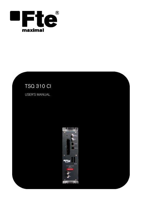
<strong>TSQ</strong> <strong>310</strong> <strong>CI</strong><br />
USER’S MANUAL
User’s manual · <strong>TSQ</strong> <strong>310</strong> <strong>CI</strong><br />
NOTE: This user’s guide is adapted to software version 000D of <strong>TSQ</strong> <strong>310</strong> <strong>CI</strong> dated 12/04/2011.<br />
For future software updates, you can download the user’s guide from the following website:<br />
http://www.ftemaximal.com/<br />
Chapter 1. Installation.<br />
1.1. Safety Measures<br />
1.- Never place the device next to hot sources.<br />
2.- Never undergo the device to temperatures that exceed its level of operation.<br />
3.- Never expose the device to leakings nor spatterings.<br />
4.- Never place objects that contain liquids over the device.<br />
5.- Respect the ventilation slots of the device, do not cover them with any kind of object.<br />
6.- The space around the device must be free of objects, in a minimum radius of 40cm.<br />
7.- Avoid locations with possibilities of spilling liquids on the inside of the device, and with important changes of<br />
temperature.<br />
8.- Never open the device by yourself due to electric risk. In case of problems, go always to qualified technicians<br />
9.- Never, under no circumstances, open the device when connected to the electrical net..<br />
10.- During the handling it is better to disconnect the device from the electrical net.<br />
11.- Obey the electricity security rules during the assembling. Use materials that obey the current law.<br />
12.- The connecting plug must be accessible in a fast and simple way to have a fast disconnection.<br />
13.- Never touch the plug with wet hands. Also, disconnect always the device before handling the connections.<br />
14.- Never put any heavy object over the device, since it could get damaged.<br />
15.- If the device is going to remain some time without use, it is recommendable to disconnect it from the electrical net.<br />
16.- The repairmen and the maintenance of the device must be done by TV and radio specialised technicians.<br />
1.2. Box content<br />
Quick installation guide 2 x Bridge F male – F male DC Cable<br />
<strong>TSQ</strong> <strong>310</strong> <strong>CI</strong> Cable 12 cm PIN to PIN RJ45 – RJ45 Stopper<br />
- 1 - <strong>TSQ</strong> <strong>310</strong> <strong>CI</strong> version_en_1.0 <strong>FTE</strong> maximal
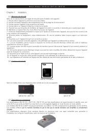
1.3. Description and connections<br />
User’s manual · <strong>TSQ</strong> <strong>310</strong> <strong>CI</strong><br />
The module <strong>TSQ</strong> <strong>310</strong> <strong>CI</strong> is used for the reception of free channels that obey the DVB-S / DVB-S2 standards. Each<br />
module allows the reception of a complete transponder in DVB-S (QPSK) / DVB-S2 (QPSK/8PSK), and the subsequent<br />
modulation in DVB-C (QAM) of it.<br />
A feature of this equipment is its modulator in Vestigial Side Band (or VSB). This modulation can be used to distribute<br />
adjacent channels in one distribution without any intermodulation problem.<br />
Each module has one Loop connector to cascade several modules at input and a Mix connector to do same in output<br />
channels.The output channel is selectable between C2 and C69.<br />
All parameters are programmed by the means of PRO 201 or the EVO or MINI series of field strength meter, and they are<br />
monitored in the display of programmer or in the 5” TFT screen of field strength meter.<br />
<strong>TSQ</strong> <strong>310</strong> <strong>CI</strong> has two Common Interface slots.<br />
<strong>TSQ</strong> <strong>310</strong> <strong>CI</strong><br />
1<br />
2<br />
3<br />
4<br />
5<br />
6<br />
7<br />
8<br />
9<br />
1. Two-colored led*: It indicates the different states of the device.<br />
2. <strong>CI</strong>: 2x Common Interface<br />
3. OUT: This connector supplies the modulated channel according to the<br />
selected standard in the module and mixes it with all the signals that it<br />
receives throught the MIX connector<br />
4. MIX: Input of mixing of the module.<br />
5. LNC IN: To connect to the LNC or to the LOOP OUT output of the<br />
previous module<br />
6. LOOP OUT: To connect to the ANT IN input of the next module.<br />
7. RS 232: Ethernet connector to cascade modules with the RCM <strong>310</strong><br />
telecontrol unit with the RJ45/RJ45 cable provided.<br />
8. PRO 201: Ethernet connector to make the programming with the<br />
programmer.<br />
9. DC connectors: It has two connectors for input/output.<br />
*States of two-colored leds<br />
1. Initialization mode<br />
- Green: main application charged.<br />
- Blinking Green: Completing the initial sequence, at the moment when the module gets initialized, the led will turn<br />
into one of the states the operating mode.<br />
- Red: Phase of initializing the module.<br />
2. Operative Mode<br />
- Green: The system is working properly.<br />
- Orange: At least one critical event has been recorded in the module. The led will only change into green when<br />
the registration of events has been read by the programmer.<br />
- Red: Error or alert detected in the running of the device, the led will be on only as long as the error/alert is<br />
present. Once the error or the alert disappears, the led will change into orange because the error/alert is stored in<br />
the registration of events.<br />
3. Programming mode<br />
- When the module detects an external programmer, the led will blink in the next sequence: green-orange-red.<br />
- Once you leave the programming mode, the led will turn into the corresponding operating mode.<br />
- 2 - <strong>TSQ</strong> <strong>310</strong> <strong>CI</strong> version_en_1.0 <strong>FTE</strong> maximal
Stages of transmodulator <strong>TSQ</strong> <strong>310</strong> <strong>CI</strong><br />
User’s manual · <strong>TSQ</strong> <strong>310</strong> <strong>CI</strong><br />
Input<br />
Selection of a tuned satellite transponder<br />
Transmodulation<br />
The tuned channels of the transponder are modulated according to the DVB-C rules. If the transponder has encoded<br />
channels, in order to distribute them freely you have to install the PCM<strong>CI</strong>A + subscriber card in the Common Interface<br />
Out<br />
Configuration of the channels and output parameters<br />
1.4. Programming<br />
<strong>TSQ</strong> <strong>310</strong> has two ethernet connectors. In order to make the programming of the module you have to connect the<br />
corresponding programmer to PRO 201 connector.<br />
You can make the programming through the PRO 201 programmer and also through the mediaMAX EVO and mediaMAX<br />
MINI field strength meter.<br />
1.4.1. Programming modes<br />
With mediaMAX EVO / mediaMAX MINI field strength<br />
meter you can carry out the programming of all the<br />
modules consecutively as long as they are interconnected<br />
with each other through the RJ-45 cable supplied with<br />
each unit.<br />
Through PRO 201, the programming is made module by<br />
module.<br />
- 3 - <strong>TSQ</strong> <strong>310</strong> <strong>CI</strong> version_en_1.0 <strong>FTE</strong> maximal
User’s manual · <strong>TSQ</strong> <strong>310</strong> <strong>CI</strong><br />
1.4.2. Programming<br />
Below you will find the steps to follow in order to make the programming both from corresponding EVO and MINI field<br />
strength meter as well as from PRO 201.<br />
mediaMAX EVO / mediaMAX MINI<br />
In order to start programming the <strong>TSQ</strong> <strong>310</strong> transmodulator, you will have to go to “Tools” option through the key 8 of your<br />
field strength meter and to select the “Prog Transmodulators “option.<br />
Then, it will proceed to recognize the module and to show the main menu. In the “Prog. Transmodulators” are shown the<br />
different configuration options that this tool offers:<br />
1. Module selection<br />
The field strength meter allows carrying out the programming of one or several transmodulators from an only<br />
transmodulator.<br />
Without interconnection of modules.<br />
An only module connected<br />
Interconnection of several modules, you can select which<br />
modules you wish to program.<br />
- 4 - <strong>TSQ</strong> <strong>310</strong> <strong>CI</strong> version_en_1.0 <strong>FTE</strong> maximal
User’s manual · <strong>TSQ</strong> <strong>310</strong> <strong>CI</strong><br />
2. State of the module<br />
In the option “State of the module” are specified the main parameters of the module at this moment.<br />
- Transmodulator input: It indicates whether the module is hooked or without<br />
signal.<br />
- Input bit rate: Transfers of data in the satellite tuner input.<br />
- Output bit rate: Transfer of data in the module output.<br />
- BER before and after Viterbi: It indicates the error rate of bits of the input<br />
signal before and after the correction produced by Viterbi algorithm.<br />
- MER: Parameter that indicates the quality of the input modulated digital signal,<br />
expressed in dB.<br />
- Noise Margin: It indicates the difference between the value of current C/N<br />
and the value of C/N at the point of pixilation of the signal, that is, the quantity<br />
of dBs of C/N measure that are needed to lose the input signal.<br />
-Temperature: It indicates the current temperature of the module in ºC.<br />
3. Input configuration<br />
In this option you will be able to configure the input parameters of the satellite<br />
signal:<br />
- Local oscillator: Selection of the local oscillator that you wish to use: FI, KU, C,<br />
K9750, K10000, K10600, K10700, K10750, K11250, K11300, K11325.<br />
- Frequency (MHz): Transponder frequency that you wish to tune.<br />
- Symbol speed: Symbol speed required by the transponder.<br />
- Auto symbol rate: You will be able to select if the detection of the Symbol<br />
Rate is going to be Automatic (On) or Manual (Off).<br />
- In Manual mode (Off), the value of the Symbol Rate should be fixed<br />
by the user based on the provider’s information.<br />
- In Automatic mode (On), the meter will automatically identify the SR<br />
when a Satellite carrier is tuned. This feature is very useful when the<br />
provider’s information is unknown.<br />
The SR value found will appear in the field of selection of the SR menu. This value found by the meter could not<br />
correspond exactly to the real broadcast SR, but to a very close value.<br />
Note: The Automatic Symbol Rate feature does not work when the carrier quality is very poor or/and with a very<br />
low Power Level.<br />
- DVB: This option allows selecting the standard DVB of the transponder that you want to tune. Options:DVB-S1,DVB-S2<br />
and auto<br />
- LNB Feeding: In this option you can set the parameters concerning the LNB:<br />
- Voltage RF IN: 13V, 18V and Off.<br />
- Tone 22 kHz: Off, and Auto. In the<br />
- Switch DiseqC: A, B, C, D and Off.<br />
- 5 - <strong>TSQ</strong> <strong>310</strong> <strong>CI</strong> version_en_1.0 <strong>FTE</strong> maximal
User’s manual · <strong>TSQ</strong> <strong>310</strong> <strong>CI</strong><br />
4. Modulator configuration<br />
This option allows you to configure the DVB-C modulator that the device has.<br />
- Symbol speed: The available symbol speed ranges from 1 to 6.96 MS/s.<br />
In order to estimate the output symbol speed you have to take into<br />
account the following parameters: input modulation, input symbol<br />
speed, input FEC, output modulation.<br />
For example, for a 8PSK signal with 22000 MS/s and a FEC 2/3, the output<br />
symbol speed should be calculated according to the chosen QAM modulation.<br />
V<br />
SYMBOL.OUT<br />
V<br />
FEC<br />
SYMBOL.IN<br />
<br />
nºbitsymbol<br />
nºbit symbol<br />
PSK <br />
2<br />
8<br />
22000 3<br />
3<br />
<br />
QAM nºbitsymbolQAM<br />
<br />
Modulation QPSK 8PSK 16 QAM 32 QAM 64 QAM 128 QAM 256 QAM<br />
Number of bits per<br />
symbol<br />
2 3 4 5 6 7 8<br />
Modulation 16 QAM 32 QAM 64 QAM 128 QAM 256 QAM<br />
Symbol speed (MS/s) 11000 8800 7333 6286 5500<br />
- Spectrum inversion: Activate or deactivate the spectrum inversion in the modulation.<br />
- Modulation: Modulation Format. Options: 16 QAM, 32 QAM, 64 QAM, 128 QAM, 256 QAM.<br />
- Roll-off factor: Roll-off factor reduces the interference between symbols thanks to the raised cosine filtering, the bigger<br />
this value is, the less interference between symbols that will be caused. Typical Value according to rules DVB-C =15 %.<br />
Options: 15 %,13%.<br />
5. Output configuration<br />
In this option you can configure the different parameters of the cable signal.<br />
- Channel standard: It allows you to select the channelling of the cable signal<br />
standards. Options: BG, BG, PAL BG IT, 11, M NTSC, PAL M, PAL N, PAL DK ,<br />
PAL I, BB_AU, DK PAL, L PAL.<br />
- Channel: Output channel of the cable modulation. When you select the output<br />
channel, the field “Frequency (MHz)” will be modified automatically, adapting<br />
itself to the selected channel. Options: C2-C69.<br />
- Frequency (MHz): Output frequency of cable modulation. When you modify<br />
this field, the field “Channel” will be also modified, indicating the channel<br />
equivalent to the selected frequency in the case that this frequency<br />
corresponds to the frequency of a channel. Options: 47-862 MHz.<br />
- Level: Regulation of the output level of the modulated signal. Options: 0-15dB.<br />
- Calibration: Allows the realization of two tests in order to verify the correct<br />
running of the device.<br />
- Output deactivate: It allows activating or deactivating the output of<br />
transmodulator.<br />
- Pure carries output: It allows activating or deactivating the DVB-C<br />
modulation, allowing visualizing the carrier without modulation in the<br />
selected frequency.<br />
- 6 - <strong>TSQ</strong> <strong>310</strong> <strong>CI</strong> version_en_1.0 <strong>FTE</strong> maximal
6. System<br />
This option provides information of the transmodulator.<br />
User’s manual · <strong>TSQ</strong> <strong>310</strong> <strong>CI</strong><br />
- System logfile: In this field are indicated the registered events in the module.<br />
- Read log: It allows reading the registered events in the module.<br />
- Clear log: It allows deleting all events stored until this moment.<br />
- Export log to USB: It allows you to export all events registered to the<br />
connected USB device.<br />
- NM low Limit (dB): An event of error will be recorded when the value of<br />
Noise Margin is lower than the set value.<br />
- NM hight limit (dB): Once the event of error is recorded (Noise Margin<br />
< Limit Lower NM), this will be Noise Margin value that will have to be<br />
exceed so the module stops being in error.<br />
- Clear log all devices. It allows deleting the events report of all the<br />
interconnected modules.<br />
- Factory default: This option restores the values by default of the transmodulator.<br />
- System information: It allows you to visualize the basic information of the<br />
module: model, no of series, firmware version, etc.<br />
- Settings: This option allows saving and loading the configuration of the module,<br />
carrying out firmware update or making an adjustment of the time and date of the<br />
module.<br />
- Clock:<br />
- Set Date and time: Setting of the date and time of<br />
transmodulator. It is appropriate to maintain these parameters set<br />
in order to have the registration of errors linked to the current<br />
time and date.<br />
- Alias:<br />
- Set date/time all devices: Loading the current date and time of<br />
the module in the rest of interconnected modules.<br />
- Write alias: It allows you to assign a name/alias to the module<br />
you are programming. Option only available when the Alias Auto<br />
option is configures as “none” (manual mode).<br />
- Auto Alias: It allows configuring the name/alias of the modules<br />
automatically. Options: Channel, Frequency, Service, None.<br />
- Upgrade:<br />
- Send Firmware from USB: It allows carrying out the firmware<br />
update from the USB device.<br />
- Send firmware to all: It allows carrying out the update of all the<br />
modules that are interconnected at the same time.<br />
- 7 - <strong>TSQ</strong> <strong>310</strong> <strong>CI</strong> version_en_1.0 <strong>FTE</strong> maximal
User’s manual · <strong>TSQ</strong> <strong>310</strong> <strong>CI</strong><br />
- Configure all devices:<br />
- Input values to all devices: It allows copying the current input<br />
configuration in all the interconnected modules.<br />
- Modulator values to all devices: It allows copying the<br />
configuration of the current modulator in all the interconnected<br />
modules.<br />
- Output values to all devices: It allows copying the current<br />
output configuration in all the interconnected modules.<br />
- Factory default to all devices: It allows making values by default<br />
to all the interconnected modules.<br />
7. Program management<br />
- New program: This option allows creating a program with the current<br />
configuration of a module or group of modules.<br />
- Load program: It allows loading a previously created program on a module or<br />
group of modules.<br />
- Delete program: It allows deleting a program.<br />
- Device to process:<br />
- Current: The creation or loading of a program will be applied only in the<br />
module that is currently connected.<br />
- All: The creation or loading of a program will be applied to the whole<br />
group of connected modules.<br />
- Working disk: With this option we have the possibility of choosing if we want to<br />
work into the internal disk or in the external storage device USB 2.0.<br />
Once the option is selected, a dialog box will appear and we will be able to choose among three different options:<br />
- Auto: The Meter decides where the data will be stored. If there is external memory connected, the Meter will<br />
store the data in it. If not, it will use the internal memory.<br />
- USB: The Meter always will try to use the external memory connected to the USB port. If this memory has not<br />
been connected an error message will be shown, reminding that there was an error storing the data and it will be<br />
not stored.<br />
- Internal: Always the internal memory is used to store the data.<br />
- Load programs from USB: This option allows importing programs from a USB memory to the field strength meter. Before<br />
using this option you must connect a USB memory.<br />
- Save programs to USB: This option allows copying the programs stored in the external USB 2.0 storage device.<br />
- Write Alias: It allows saving the alias of the module in the program. Options: Yes/No<br />
8. Set Output Services<br />
This option allows making the selection of the services that you wish to include in<br />
the output multiplex.<br />
- Add/Remove services: It allows adding the services to the multiplex and also<br />
removing the ones previously included. The lower bar informs about the available<br />
space in the output multiplex. As you add more services, the space available will<br />
decrease.<br />
Once you have tuned a transponder in the “Input Set Up” section and you have<br />
selected the DVB-C modulator configuration in the “Modulator Set Up” section,<br />
you can make the assignment of the services that are going to be included in the<br />
output multiplex “Adding/Removing services”.<br />
- 8 - <strong>TSQ</strong> <strong>310</strong> <strong>CI</strong> version_en_1.0 <strong>FTE</strong> maximal
Adding services:<br />
User’s manual · <strong>TSQ</strong> <strong>310</strong> <strong>CI</strong><br />
1. Select “Service to add” option 2. Select one of the transponder<br />
services you want to add.<br />
3. Once you have chosen the<br />
service, select the “Add/Remove”<br />
button to include the service in<br />
the multiplex.<br />
Note: It is not recommended to exceed the 85% of the maximum capacity of the multiplex due to the possible<br />
variability of the bits rate of the inputs services.<br />
Removing services:<br />
1. Select the “Service to remove”<br />
option.<br />
Recomendad capacity<br />
(lower to 85%)<br />
2. Select one of the transponder<br />
services you want to remove.<br />
Excessive capacity<br />
It is recommended to remove<br />
services<br />
3. Once you have chosen the<br />
service, select the “Add/Remove”<br />
button to remove the service in<br />
the multiplex.<br />
- 9 - <strong>TSQ</strong> <strong>310</strong> <strong>CI</strong> version_en_1.0 <strong>FTE</strong> maximal
User’s manual · <strong>TSQ</strong> <strong>310</strong> <strong>CI</strong><br />
- Remove all services: It allows removing all the services included in the<br />
multiplex.<br />
- Modify LCN: The LNC function allows assigning automatically a<br />
predetermined position to each one of the services of the multiplex. This<br />
function will allow the users who have a receiver with LNC support to make the<br />
ordination of channels automatically.<br />
Note: If in the existing installation there are already services that have<br />
LNC system, you will have to configure the position of the module<br />
services in order to avoid conflicts with other net services.<br />
- Bandwith limitation: It allows selecting the % of the capacity of the output<br />
channel.<br />
- Auto service addition:<br />
- On: It selects the services automatically when an input carrier is tuned<br />
and when the list of selected services is empty. The receiver will have<br />
this state by default.<br />
- Always: It selects the services automatically every time a new input<br />
carrier is tuned. This state is only recommended to be used for making<br />
test in the module.<br />
- Off: The automatic mode is deactivated; the services have to be<br />
manually selected.<br />
- Advanced settings:<br />
- Network: It allows making the adjustment of the identification<br />
parameters of the multiplex.<br />
- TS ID: Transport Stream identification value. It is<br />
recommended to configure a value different from TS ID for<br />
each one of the output multiplex configured.<br />
- Net ID: Net identification value<br />
- Original Net ID: Original net identification value<br />
- Network Name: Name associated with the net.<br />
- Tables: It allows modifying the value of the following<br />
information tables of the DVB, NIT, SDT and PAT services.<br />
- Services:<br />
- Change service name: It allows changing the name of the<br />
service manually. In order to do so, please choose the service<br />
in the first line and then write the new name in the second line.<br />
Then you have to press “modify” in order to save the changes.<br />
- 10 - <strong>TSQ</strong> <strong>310</strong> <strong>CI</strong> version_en_1.0 <strong>FTE</strong> maximal
User’s manual · <strong>TSQ</strong> <strong>310</strong> <strong>CI</strong><br />
- HDSimulCast: In cases where we receive in an installation<br />
the same channel in high definition and in standard definition,<br />
the HD Simualcast function allows to exchange the position of<br />
the LNC of both channels. If the user has a device compatible<br />
to HD Simulcast and the module has been correctly<br />
configured, when tuning the standard definition channel, it will<br />
move to its position in high definition automatically.<br />
This option allows modifying manually the position of the LNC,<br />
exchanging the standard position into the high definition<br />
position. In the first line you have to select the high definition<br />
service and in the second line you have to select the same<br />
service but in standard definition.<br />
- Change in Service ID: From this position you can change the<br />
PID Number of the chosen service.<br />
Next it is attached the identification table (NID/ONID) of the main satellites. You will be able to find more information in<br />
the law ETSI TR 101 162 v1.2.1.<br />
Satellite Net ID Original Net ID Description<br />
Hotbird 13ºE (Eutelsat 13ºE) 318 318 Eutelsat 13ºE System<br />
Astra 19.2ºE 1 1 Astra Satellite Network 19,2ºE<br />
Astra 23ºE 3-25 3-25 Astra n (n=1-23)<br />
Astra 28,2ºE 2 2 Astra Satellite Network 28,2ºE<br />
Nilesat 7ºW 2048 2048 Nilesat 101<br />
Hispasat 30ºW 33 33 Hispasat Network 1<br />
9. Common Interface<br />
This option allows checking the information and configuring the parameters<br />
regarding the conditional access.<br />
- Selecting Slot: It selects the Slot where the CAM for decoding the services is<br />
inserted.<br />
- <strong>CI</strong> Menu: From here you can reach the menu of the card inserted in the CAM.<br />
- Decrypted: From this option you can add or remove manually the services that<br />
are being decoded by the card.<br />
- 11 - <strong>TSQ</strong> <strong>310</strong> <strong>CI</strong> version_en_1.0 <strong>FTE</strong> maximal
User’s manual · <strong>TSQ</strong> <strong>310</strong> <strong>CI</strong><br />
- Deactivating all decrypted: From this option you can remove all the services that<br />
are decoding the conditional access card.<br />
PRO 201<br />
Note: From PRO 201 programmer you can only carry out the programming of a single module, in order to carry<br />
out the programming of several modules at the same time you have to use a mediaMAX EVO or mediaMAX<br />
MINI series field strength meter.<br />
When you connect the PRO 201 programmer, it will proceed to recognize the<br />
module and to show the main menu.<br />
In the main menu are shown the different options for configuring the<br />
transmodulator.<br />
We have to use the “Up” and “Down” buttons of the keyboard in order to move to<br />
the different options, and to get into the submenus we have to press “OK” button.<br />
1. Manual<br />
Inside the “manual” menu there are specified the different options for<br />
setting up the input, output and modulation parameters.<br />
1. This field shows the type of parameter that is selected at the moment.<br />
Options: Input Sat, Out Cab, Out TV.<br />
2. This field shows the parameter that is selected. In order to move<br />
around the different options we have to use the “Up” and “Down” buttons<br />
of the keyboard.. Click on OK to edit the selected parameter and<br />
Right/Left for changing it. Once it is configured press OK.<br />
Satellite input ( Input Sat)<br />
In these options you will be able to configure the input parameters of the satellite<br />
signal:<br />
- L.O. freq (Local oscillator): Selection of the local oscillator that you wish to use:<br />
FI, KU, C, K9750, K10000, K10600, K10700, K10750, K11250, K11300,<br />
K11325 .<br />
<strong>TSQ</strong><strong>310</strong><strong>CI</strong><br />
>Manual< Config<br />
Auto<br />
<strong>TSQ</strong><strong>310</strong><strong>CI</strong> *Input Sat<br />
RF level: 013<br />
>LO Freq: LO KU<br />
Freq: 11509<br />
<strong>TSQ</strong><strong>310</strong><strong>CI</strong> *Input Sat<br />
Symbol Rate: 27500<br />
>Antenna: 13V+22k<br />
Diseqc: NONE<br />
- Freq (Input Frequency (MHz)): Transponder frequency that you wish to tune. In order to introduce the frequency, press<br />
the “OK” button and the cursor will be placed over the frequency. With the keys of the cursor, we can move through all the<br />
digits and change the values. Press “OK” in order to save the value.<br />
- Symbol Rate: Symbol speed required by the transponder. In order to introduce the symbol rate, press the “OK” button and<br />
the cursor will be placed over the frequency. With the keys of the cursor, we can move through all the digits and change<br />
the values. Press “OK” in order to save the value.<br />
- Antenna: Feeding/tone towards the LNC. Options: 0V, 13V, 13V+22kHz, 18V, 18V+22KHz, 13V+AUT, 18V+AUT.<br />
- DiseqC: In this option you can set the DiseqC configuration: A, B, C, D and None.<br />
- 12 - <strong>TSQ</strong> <strong>310</strong> <strong>CI</strong> version_en_1.0 <strong>FTE</strong> maximal<br />
1<br />
2
User’s manual · <strong>TSQ</strong> <strong>310</strong> <strong>CI</strong><br />
- Auto SR (Auto Symbol Rate): You will be able to select if the detection of the Symbol Rate is going to be Automatic (On)<br />
or Manual (Off).<br />
- In Manual mode (Off), the value of the Symbol Rate should be fixed by the user based on the provider’s<br />
information.<br />
- In Automatic mode (On), the meter will automatically identify the SR when a Satellite carrier is tuned. This<br />
feature is very useful when the provider’s information is unknown.<br />
The SR value found will appear in the field of selection of the SR menu. This value found by the meter could not<br />
correspond exactly to the real broadcast SR, but to a very close value.<br />
Note: The Automatic Symbol Rate feature does not work when the carrier quality is very poor or/and with a very<br />
low Power Level.<br />
- Mode: This option allows selecting the standard DVB of the transponder that you want to tune. Options: DVB-S1,<br />
DVB-S2 and auto.<br />
Cable modulator ( Out Cable)<br />
This option allows you to configure the DVB-C modulator that the device has.<br />
- Spectrum inversion: Activate or deactivate the spectrum inversion in the<br />
modulation.<br />
- Modulation: Modulation Format. Options: 16 QAM, 32 QAM, 64 QAM, 128 QAM,<br />
256 QAM.<br />
- Roll-off factor: Roll-off factor reduces the interference between symbols thanks to the raised cosine filtering, the bigger<br />
this value is, the less interference between symbols that will be caused. Typical Value according to rules DVB-C =15 %.<br />
Options: 1.5, 1.3.<br />
- Symbol speed: The available symbol speed ranges from 1000 to 7000 S/s.<br />
In order to estimate the output symbol speed you have to take into account the following parameters: input<br />
modulation, input symbol speed, input FEC, output modulation.<br />
For example, for a 8PSK signal with 22000 MS/s and a FEC 2/3, the output symbol speed should be calculated<br />
according to the chosen QAM modulation.<br />
V<br />
SYMBOL.OUT<br />
V<br />
FEC<br />
SYMBOL.IN<br />
<br />
nºbitsymbol<br />
nºbit symbol<br />
PSK<br />
2<br />
8<br />
22000 3<br />
3<br />
<br />
QAM nºbitsymbolQAM<br />
<br />
Modulation QPSK 8PSK 16 QAM 32 QAM 64 QAM 128 QAM 256 QAM<br />
Number of bits per<br />
symbol<br />
2 3 4 5 6 7 8<br />
Modulation 16 QAM 32 QAM 64 QAM 128 QAM 256 QAM<br />
Symbol speed (MS/s) 11000 8800 7333 6286 5500<br />
Output configuration ( TV output)<br />
In these options you can configure the output parameters of the terrestrial signal.<br />
- RF Channel (MHz): Output frequency of terrestrial modulation. In order to<br />
introduce the frequency, press the “OK” button and the cursor will be placed over<br />
the frequency. With the keys of the cursor, we can move through all the digits and<br />
change the values. Press “OK” in order to save the value. Options: 47-862 MHz.<br />
- RF Level: Regulation of the output level of the modulated signal. Options: 0-15dB.<br />
<strong>TSQ</strong><strong>310</strong><strong>CI</strong> * Out Cable<br />
Modulacion: 64<br />
>Roll-off: 1.5<br />
Symbol speed: 1000<br />
<strong>TSQ</strong><strong>310</strong><strong>CI</strong> *Out TV<br />
>RF Channel: 474000<br />
RF Level: 013<br />
Summary table:<br />
Satellite input Cable output TV output<br />
- L.O. frequency<br />
- Invert (Spectrum Inversion)<br />
- RF Channel<br />
- Input Frequency<br />
- Modulation<br />
- RF Level<br />
- Symbol Rate<br />
- Roll-off factor<br />
- Antenna<br />
- Diseqc<br />
- Symbol rate auto<br />
- DVB Mode<br />
- Symbol speed<br />
- 13 - <strong>TSQ</strong> <strong>310</strong> <strong>CI</strong> version_en_1.0 <strong>FTE</strong> maximal
User’s manual · <strong>TSQ</strong> <strong>310</strong> <strong>CI</strong><br />
2. Auto<br />
This option allows saving and loading the configuration of the module in the PRO<br />
201 programmer.<br />
- Read from module: It stores the current configuration of the module in the memory of the programmer. The steps to<br />
make a correct reading of the headend are specified below:<br />
<strong>TSQ</strong><strong>310</strong><strong>CI</strong><br />
> *Read from Module*<br />
*Write to Module *<br />
1. Select the option “Read from<br />
module” through Up/Down buttons.<br />
Press OK to continue<br />
2. Select the position of “CFG”<br />
memory where you wish to save the<br />
current configuration of the module.<br />
3. A window will appear and it will let<br />
you know that the reading made has<br />
been correct<br />
- Write to module: It loads in the module one of the configurations previously saved in the memory of the programmer. The<br />
steps to make a correct configuration of the headend are specified below:<br />
<strong>TSQ</strong><strong>310</strong><strong>CI</strong><br />
> *Write to Module *<br />
*Read from Module*<br />
1. Select the option “Write to module”<br />
through Up/Down buttons. Press OK<br />
to continue<br />
2. Select the position of the “CFG”<br />
memory that you wish to copy in the<br />
module. Please verify that the data of<br />
the selected memory correspond to<br />
the channel that you wish to copy.<br />
3. Config<br />
In “Config” option the information concerning the transmodulator is given.<br />
- Read log: It allows reading the registered events in the module.<br />
<strong>TSQ</strong><strong>310</strong><strong>CI</strong><br />
LCN<br />
>Read LOG file<br />
Delete LOG file<br />
1. Select the option “Read LOG file”<br />
through Up/Down buttons. Press OK<br />
to continue<br />
<strong>TSQ</strong><strong>310</strong><strong>CI</strong><br />
Free position<br />
<strong>TSQ</strong><strong>310</strong><strong>CI</strong><br />
CFG:01<br />
Freq:11362 Sr:27500<br />
Output Freq:850000<br />
<strong>TSQ</strong><strong>310</strong><strong>CI</strong><br />
OK to Show LOG<br />
CFG:03<br />
<strong>TSQ</strong><strong>310</strong><strong>CI</strong><br />
> *Read from Module*<br />
*Write to Module *<br />
<strong>TSQ</strong><strong>310</strong><strong>CI</strong><br />
Operation finish<br />
<strong>TSQ</strong><strong>310</strong><strong>CI</strong><br />
Operation finish<br />
3. A window will appear and it will let<br />
you know that the configuration made<br />
has been correct<br />
<strong>TSQ</strong><strong>310</strong><strong>CI</strong><br />
LCN<br />
>Read LOG file<br />
Delete LOG file<br />
<strong>TSQ</strong><strong>310</strong><strong>CI</strong><br />
N:00001 Status:03<br />
07/02/11 09:05:02<br />
Front-end lock<br />
2. Press OK again to show the log file. 3. A new window will appear. It will<br />
show the information about the<br />
registered events in the module. Press<br />
the following keys in order to scroll up<br />
and down the screen: “up/down”.<br />
- Delete LOG file: It allows deleting all events stored until this moment.<br />
- Factory default: This option restores the values by default of the transmodulator.<br />
- Update FW: It allows carrying out the firmware update from the programmer.<br />
- Output services: This option allows making the selection of the services that you wish to include in the output multiplex.<br />
Once you have tuned a transponder and you have selected the DVB-T/DVB-H modulator configuration, you can make the<br />
assignment of the services that are going to be included in the output multiplex “Adding/Removing services”.<br />
- 14 - <strong>TSQ</strong> <strong>310</strong> <strong>CI</strong> version_en_1.0 <strong>FTE</strong> maximal
- Add Services<br />
<strong>TSQ</strong><strong>310</strong><strong>CI</strong><br />
BW usage 000%<br />
Delete services<br />
>Add services<br />
1. Select the option “Add services”<br />
through Up/Down buttons. Press OK<br />
to continue.<br />
- Delete Services<br />
<strong>TSQ</strong><strong>310</strong><strong>CI</strong><br />
BW usage 083%<br />
>Delete services<br />
Add services<br />
1. Select the option “Delete services”<br />
through Up/Down buttons. Press OK<br />
to continue.<br />
User’s manual · <strong>TSQ</strong> <strong>310</strong> <strong>CI</strong><br />
<strong>TSQ</strong><strong>310</strong><strong>CI</strong><br />
Input 035 %<br />
PID:06200 arte HD<br />
+Add<br />
2. Select one of the transponder<br />
services you want to add, through<br />
Left/Right keys and select the “+Add”<br />
button to include the service in the<br />
multiplex<br />
<strong>TSQ</strong><strong>310</strong><strong>CI</strong><br />
Input 083 %<br />
PID:06000 Das Erste<br />
-Rem --All<br />
2. Select the service you want to<br />
delete with the Left/Right keys. Then<br />
press OK over “-Rem” in order to<br />
remove it, or press OK over “--All” in<br />
order to delete all the services of the<br />
multiplex.<br />
3. A window will appear and it will let<br />
you know that the operation made has<br />
been correct.<br />
3. A window will appear and it will let<br />
you know that the operation made has<br />
been correct.<br />
Note: It is not recommended to exceed the 85% of the maximum capacity of the multiplex due to the possible<br />
variability of the bits rate of the inputs services.<br />
- LCN: The LNC function allows assigning automatically a predetermined position<br />
to each one of the services of the multiplex. This function will allow the users who<br />
have a receiver with LNC support to make the ordination of channels<br />
automatically.<br />
Select a channel through Left/Right buttons and introduce the position. Press the<br />
“OK” button and the cursor will be placed over the number. With the keys of the<br />
cursor, we can move through all the digits and change the values. Press “OK” in<br />
order to save the changes<br />
<strong>TSQ</strong><strong>310</strong><strong>CI</strong><br />
Operation finish<br />
<strong>TSQ</strong><strong>310</strong><strong>CI</strong><br />
Operation finish<br />
<strong>TSQ</strong><strong>310</strong><strong>CI</strong><br />
LCN:00004 arte HD<br />
Note: If in the existing installation there are already services that have LNC system, you will have to configure<br />
the position of the module services in order to avoid conflicts with other net services.<br />
- Decrypt services: From this option you can add or remove manually the services that are being decoded by the card:<br />
- Delete services<br />
- Add services<br />
- Date / Hour: Setting of the date and time of transmodulator. It is appropriate to maintain these parameters set in order to<br />
have the registration of errors linked to the current time and date.<br />
- SW version info: It allows you to visualize the basic information of the module: model, firmware version, etc.<br />
- Global Update: It allows carrying out the update of all the modules that are interconnected at the same time.<br />
- 15 - <strong>TSQ</strong> <strong>310</strong> <strong>CI</strong> version_en_1.0 <strong>FTE</strong> maximal
1.5. Accessories and example of installation<br />
Example of installation<br />
Accessories<br />
User’s manual · <strong>TSQ</strong> <strong>310</strong> <strong>CI</strong><br />
In order to guarantee the right running of the different equipments of the<br />
installation, we recommend you to provide the inputs and outputs which are<br />
not used with a 75 load.<br />
Programmer<br />
Mod. PRO 201<br />
Code 2003123<br />
Parabolic antenna OS series<br />
Mod. OS 100 AL<br />
Code 0701100<br />
Installation that consist of 6 <strong>TSQ</strong> <strong>310</strong> <strong>CI</strong> and that will allow<br />
tuning channels up to 6 different transponders and to<br />
distribute them through a network of modulated cable in<br />
DVB-C. The distributed channels need a cable receiver in<br />
order to be decoded.<br />
In order to distribute the encoded channels freely you have to<br />
install the PCM<strong>CI</strong>A + subscriber card in the Common<br />
Interface slot.<br />
Field strength meter<br />
Mod.mediaMAX EVO S2<br />
Code 3001006<br />
Wide band amplifier 47-862MHz<br />
Mod. AMP <strong>310</strong> P<br />
Code 2003520<br />
Field strength meter<br />
Mod. mediaMAX MINI S2T<br />
Code 3001026<br />
Mixer<br />
Mod. MUX <strong>310</strong><br />
Code 2003518<br />
- 16 - <strong>TSQ</strong> <strong>310</strong> <strong>CI</strong> version_en_1.0 <strong>FTE</strong> maximal
Chapter 2. Technical features<br />
User’s manual · <strong>TSQ</strong> <strong>310</strong> <strong>CI</strong><br />
Ref. <strong>TSQ</strong> <strong>310</strong> <strong>CI</strong><br />
Code 2003534<br />
Input frequancy margin 950-2150 MHz<br />
Input level -25 a -65 dBm<br />
Imput impedance 75<br />
LNB (feeding/conmutation) 13V-18V / 0-22kHz<br />
Input connector Female F connector<br />
Input LOOP losses
ESPAÑA<br />
Mogoda, 110<br />
Pol. Industrial Can Salvatella<br />
08210 Barberà del Vallès<br />
(Barcelona) España<br />
Tel. 00 34 93 729 27 00<br />
Fax. 00 34 93 729 30 73<br />
ftemaximal@ftemaximal.com<br />
www.ftemaximal.com<br />
DEUTSCHLAND<br />
Auf der Höhe, 8<br />
44536 Lünen<br />
Deutschland<br />
Tel. 00 49 (0) 23 18 78 5 - 01<br />
Fax. 00 49 (0) 23 18 78 5 - 200<br />
info@ftemaximal.de<br />
www.ftemaximal.de<br />
FRANCE<br />
16 ZAE Les Mouilles<br />
74570 Groisy<br />
Tel. 00 33 450 68 80 17<br />
Fax. 00 33 450 68 84 68<br />
sav@ftemaximal.fr<br />
www.ftemaximal.com<br />
PORTUGAL<br />
Rua José Carlos Ary dos Santos<br />
A-das-Lebres (Loures)<br />
2670-791 Santo Antão do Tojal<br />
Tel. 00 351 219 83 87 00<br />
Fax. 00 351 219 83 87 09<br />
ftemaximal@ftemaximal.pt<br />
www.ftemaximal.com<br />
ITALIA<br />
Via Edison, 29<br />
42040 Calerno di<br />
Sant’Ilario d’Enza (RE)<br />
Tel. 00 39 05 22 90 97 01<br />
Fax. 00 39 05 22 90 97 48<br />
fte@fte.it<br />
www.ftemaximal.com<br />
UNITED ARAB EMIRATES<br />
P.O.Box 262442<br />
Jebel Ali Free Zone<br />
Warehouse FZS5AB03<br />
Dubai<br />
Tel. 00 971 4 886 5700<br />
Fax. 00 971 4 886 5701<br />
www.ftemaximal.ae