Digilyzer DL1 User Manual
Digilyzer DL1 User Manual
Digilyzer DL1 User Manual

You also want an ePaper? Increase the reach of your titles
YUMPU automatically turns print PDFs into web optimized ePapers that Google loves.
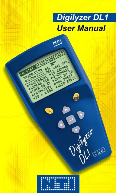
<strong>Digilyzer</strong> <strong>DL1</strong><br />
<strong>User</strong> <strong>Manual</strong>
NTi Audio Contact<br />
Headquarter: NTi Audio AG<br />
Im alten Riet 102<br />
9494 Schaan<br />
Liechtenstein, Europe<br />
Tel +423 - 239 6060<br />
Fax +423 - 239 6089<br />
E-mail info@nti-audio.com<br />
Home www.nti-audio.com<br />
NTi Audio is an ISO 9001:2008<br />
certified company.<br />
© NTi Audio AG<br />
All rights reserved.<br />
Subject to change without notice.<br />
Release 2.20 / May 2011 / Software D2.20<br />
<strong>Digilyzer</strong>, Minirator, Minilyzer, MiniSPL,<br />
MiniLINK and Minstruments are registered<br />
trademarks of NTi Audio.<br />
2<br />
Made in<br />
Switzerland
INdex:<br />
1. In t r o d u c t Io n 4<br />
CE Declaration of Conformity 4<br />
Registration 5<br />
International Warranty and Repair 6<br />
Warnings 7<br />
Test & Calibration Certificate 7<br />
Scope of Delivery 7<br />
2. ov e r v I e w 8<br />
Functions 9<br />
Monitoring 10<br />
Connectors 13<br />
Battery Replacement 14<br />
3. FIr s t st e p s 15<br />
4. Ba s Ic op e r a t Io n 18<br />
5. Me a s u r e M e n t Fu n c t Io n s 27<br />
Channel Status 27<br />
Bit Statistic 33<br />
Logger 35<br />
VU+PPM 39<br />
Level Measurement 41<br />
Level Peak 42<br />
Level RMS 43<br />
Level Sweep 45<br />
THD+N 47<br />
Scope 49<br />
6. tr o u B l e s h o o t In g 50<br />
7. ac c e s s o r I e s 51<br />
MiniLINK 51<br />
Mains Power Adapter 51<br />
Minstruments System Case 52<br />
Pouch 52<br />
8. ap p e n d I x 53<br />
1C2f Format 53<br />
Logger Event Coding 55<br />
Professional Format Coding 58<br />
Consumer Format Coding 61<br />
9. te c h n Ic a l sp e c I F Ic a t Io n 63<br />
3
1. INTroduCTIoN<br />
Congratulations and thank you for buying NTi Audio’s <strong>Digilyzer</strong><br />
<strong>DL1</strong>, a product specially suited for professional audio applications.<br />
The <strong>Digilyzer</strong> offers advanced analysis functions, expected only in<br />
much larger and more expensive systems. We are convinced you<br />
will enjoy using it!<br />
NTi Audio products are manufactured in compliance with the highest<br />
quality standards and marked with the CE sign.<br />
Ce declaration of Conformity<br />
We, the manufacturer<br />
NTi Audio AG<br />
Im alten Riet 102<br />
9494 Schaan<br />
Liechtenstein, Europe<br />
hereby declare that the product <strong>Digilyzer</strong> <strong>DL1</strong>, released in 2001,<br />
conforms to the following standards or other normative documents.<br />
EMC-Directives: 89/336, 92/31, 93/68<br />
Harmonized Standards: EN 61326-1<br />
This declaration becomes void in case of any changes on the product<br />
without written authorization by NTi Audio.<br />
Date: 01.11.2001<br />
Signature:<br />
Introduction<br />
Position of signatory: Technical Director<br />
4
egistration<br />
Introduction<br />
Register as a customer with NTi Audio and benefit from the following<br />
possibilities:<br />
• Keep your products up-to-date<br />
Access free firmware and software updates.<br />
• Activate options<br />
Enable additional functions for your products.<br />
• Access premium content<br />
Access downloads, information and specific support for your<br />
products.<br />
• Receive application and product news<br />
Sign in for the NTi Audio Newsletter.<br />
• Get fast worldwide support<br />
Register your products for fast support.<br />
• Confirm your ownership<br />
Allows us to contact you with important product notifications<br />
and provides a product record in case of loss or theft.<br />
How to register<br />
• Open the web page “http://my.nti-audio.com”.<br />
• You are prompted to login or create the My NTi Audio<br />
Account.<br />
• The web page “My NTi Audio Products” opens.<br />
• Select the product type and enter the serial number.<br />
• Confirm with “Register”.<br />
• Now the product is listed in the table “My NTi Audio<br />
Products“.<br />
5
International Warranty and repair<br />
International Warranty<br />
NTi Audio guarantees the <strong>Digilyzer</strong> <strong>DL1</strong> and its components against<br />
defects in material or workmanship for a period of one year from<br />
the date of original purchase, and agrees to repair or to replace at<br />
its discretion any defective unit at no cost for either parts or labor<br />
during this period.<br />
restrictions<br />
This warranty does not cover damages caused through accidents,<br />
misuse, lack of care, the attachment or installation of any components<br />
that were not provided with the product, loss of parts, connecting the<br />
instrument to a power supply, input signal voltage or connector type<br />
other than specified, or wrongly polarized batteries. In particular,<br />
no responsibility is granted for special, incidental or consequential<br />
damages.<br />
This warranty becomes void if servicing or repairs of the product are<br />
performed by any party other than an authorized NTi Audio service<br />
center or if the instrument has been opened in a manner other than<br />
specified in this manual.<br />
No other warranty, written or verbal, is authorized by NTi Audio.<br />
Except as otherwise stated in this warranty, NTi Audio makes no<br />
representation or warranty of any kind, expressed or implied in law<br />
or in fact, including, without limitation, merchandising or fitting for any<br />
particular purpose and assumes no liability, either in tort, strict liability,<br />
contract or warranty for products.<br />
repair of your digilyzer dL1<br />
Introduction<br />
In case of malfunction, take - or ship prepaid - your NTi Audio <strong>Digilyzer</strong><br />
packed in the original box, to the authorized NTi Audio representative<br />
in your country. For contact details see the NTi Audio web page.<br />
Be sure to include a copy of your sales invoice as prove of purchase<br />
date. Transit damages are not covered by this warranty.<br />
6
Warnings<br />
In order to avoid any problems during the operation of the instrument,<br />
follow the rules listed below:<br />
• Use the instrument for the intended purpose only.<br />
• Never connect the instrument to a high voltage output such<br />
as a power amplifier, mains power, etc.<br />
• Do not disassemble the instrument.<br />
• Never use the instrument in a damp environment.<br />
• Remove the batteries as soon as they are flat or if the<br />
instrument is not intended to be used for a longer period<br />
of time.<br />
Test & Calibration Certificate<br />
This is to certify the <strong>Digilyzer</strong> <strong>DL1</strong> is fully tested to the manufacturer’s<br />
specifications.<br />
NTi Audio recommends to calibrate this test instrument one (1) year<br />
after purchase. Thereafter the calibration- and adjustment interval is<br />
subsequently one (1) year.<br />
Scope of Delivery<br />
Introduction<br />
The following items are included with the packing:<br />
• <strong>Digilyzer</strong> <strong>DL1</strong><br />
• Rubber Cushion<br />
• Chinch-BNC Adapter<br />
• <strong>User</strong> <strong>Manual</strong><br />
7
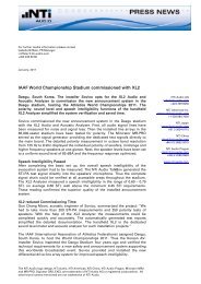
2. overvIeW<br />
The <strong>Digilyzer</strong> is a sophisticated tool used to analyze digital audio<br />
signals. It is designed for easy and quick maintenance and debugging<br />
of digital audio equipment and installations. Therefore, the <strong>Digilyzer</strong><br />
observes the signals from many points of view simultaneously. An<br />
accurate overview of the actual signal condition is displayed on a large<br />
LCD and hidden errors are visualized (e.g. consistency check).<br />
Carrier<br />
information<br />
Quick status<br />
information<br />
Overview<br />
Menu bar<br />
Fig 2-01, Overview display<br />
8<br />
PPM meter<br />
By using the <strong>Digilyzer</strong> understanding and handling digital signals is<br />
simple. However, some basic knowledge about digital audio signals<br />
is essential. Please refer to our homepage for some easy literature<br />
about digital audio basics.<br />
Interface types<br />
The <strong>Digilyzer</strong> supports all common used interface types such as AES3,<br />
S/PDIF, TOS-LINK and ADAT. This range could be further extended<br />
by using external adapters or cheap equipment e.g. a TDIF to ADAT<br />
converter.
Functions<br />
Overview<br />
The <strong>Digilyzer</strong> features many useful measurement functions which are<br />
accessible through a menu bar.<br />
Fig 2-02, Measurement functions<br />
easy operation<br />
The <strong>Digilyzer</strong> has an easy to use menu driven user interface. Changing<br />
of the settings takes place at the displayed values – there is no<br />
complex setup screen. The base element for operational functions<br />
is the cursor (inverted area) which can be navigated through the<br />
various screens by using the cursor keys. All selectable settings may<br />
be adjusted individually by pressing the enter key and selecting the<br />
requested value with the cursor keys. Confirm the setting by pressing<br />
the enter key again.<br />
Fig 2-03, <strong>DL1</strong> menu<br />
9
Monitoring<br />
Overview<br />
Fig 2-04, Changing settings<br />
10<br />
Unit selected<br />
with cursor to<br />
change setting<br />
When it comes to digital audio, one of the major problems is, that<br />
humans do not have digital ears and thus can not listen to the<br />
incoming embedded audio signal. The <strong>Digilyzer</strong> offers a wide range<br />
of functionality to make digital audio audible.<br />
What you hear is what you measure<br />
• Functions with measurement of both channels (e.g. A+B), the<br />
output of the speaker is a mix of the two channel signals. Over<br />
the headphone output you may hear the signal in stereo (channel<br />
A on the left and channel B on the right side).<br />
Both channels A+B selected<br />
Fig 2-05, Channels A+B selected
• Some functions, e.g. SCOPE, are one channel functions only. You<br />
only hear the channel which is displayed on the screen.<br />
Digital versus analog<br />
Overview<br />
Channel B selected<br />
Fig 2-06, Channel B selected<br />
Installations with digital and analog audio lines often cause headache<br />
and struggles. In reality some analog line maybe connected and the<br />
<strong>Digilyzer</strong> can not lock to the (non digital) signal. Therefore, the <strong>Digilyzer</strong><br />
has the ability of analog monitoring. The <strong>Digilyzer</strong> may not lock to the<br />
input signal digitally, but it routes the signal directly to the speaker<br />
and headphone output, so you may hear the analog input signal<br />
acoustically. For visual clarification ANALOG MONITORING ON is<br />
flashing on the display.<br />
Fig 2-07, Analog monitoring<br />
11<br />
Flashing
Debugging or listening?<br />
The built-in speaker on the rear side gives the acoustical response of<br />
the measured signal – everywhere and any time – without the need<br />
of a headphone. For the users convenience a good headphone may<br />
be connected for listening in superior quality (up to 24 bit / 96 kHz).<br />
The headphone output may be used as D/A converter, e.g. some<br />
recording with a minidisc-player is requested but no analog output<br />
is available.<br />
oops – no signal!<br />
Often no signal is found during troubleshooting at digital audio lines.<br />
Can this be? The <strong>Digilyzer</strong> offers a digital realized “AGC” (automatic<br />
gain control) to “zoom up” the digital signal. So even a change of the<br />
LSB (least significant bit) is fully audible. The tremendous dynamic<br />
range of 140 dB allows to listen to the smallest disturbances. For<br />
example someone just has closed the fader or muted the signal, so<br />
just activate the AGC and listen; even dither noise will be audible.<br />
Hotkey-symbol<br />
All the above monitoring functionalities can be controlled by using<br />
hotkeys, displayed in the FAST ACCESS SETUP menu.<br />
dual domain measurements<br />
Overview<br />
Fig 2-08, Automatic gain control<br />
Level RMS and distortion (THD+N) measurements are fundamental to<br />
check A/D converters. The complete test system even checks mixed<br />
mode applications such as A/D converters or digital mixers is available<br />
in combination with the analog signal generator Minirator MR1.<br />
12<br />
Description<br />
hotkey AGC<br />
ON/OFF
Connectors<br />
The <strong>Digilyzer</strong> includes the following connectors:<br />
AES3, 110 Ohm<br />
terminated<br />
Overview<br />
S/PDIF, 75 Ohm<br />
terminated<br />
Fig 2-09, Inputs and outputs of <strong>DL1</strong><br />
NOTES • For AES3, 75 Ohm, signals (BNC connector) use the<br />
attached Chinch-BNC adapter.<br />
• Insert a jack into the headphone output to switch<br />
of the analog monitoring with the internal speaker<br />
(e.g. during a live act).<br />
Rubber Cushions<br />
The original packaging of the <strong>Digilyzer</strong> includes a pair of rubber<br />
cushions. These may be adhered on the rear side of the device, so the<br />
output signal is made audible in good quality also whilst the <strong>Digilyzer</strong><br />
lays, e.g. on a table, with the speaker on the bottom side.<br />
Chinch-BNC Adapter<br />
The Chinch-BNC Adapter enables the measurement of the AES3id,<br />
75 Ohm standard with the <strong>Digilyzer</strong>. AES3id is especially required<br />
for the transmission of digital signals over longer cables with a cable<br />
length >100 m.<br />
13<br />
Headphone<br />
output<br />
TOS-Link /<br />
ADAT
Battery replacement<br />
Insert three pieces of 1.5 V alkaline batteries, type AA, LR6, AM3 into<br />
the <strong>Digilyzer</strong> battery compartment, as shown below.<br />
1. Press 1. Press<br />
2. Pull<br />
Overview<br />
Rubber<br />
cushion<br />
Speaker<br />
Fig 2-10, Open battery compartment Fig 2-11, Inserted batteries<br />
NOTE • The use of rechargeable NiCd- or NiMH-batteries<br />
causes shorter battery lifetime than specified.<br />
• Do not insert batteries of different types.<br />
• Note the correct polarities of the inserted batteries.<br />
• Remove the batteries as soon as they are flat.<br />
14
3. FIrsT sTeps<br />
This chapter is a quick guide explaining how to make the first<br />
measurements with the <strong>Digilyzer</strong>. The example assumes an S/PDIF<br />
signal as input (e.g. a CD player with S/PDIF output playing a music<br />
CD).<br />
1. Insert batteries<br />
2. Connect the S/PDIF signal to<br />
the RCA input.<br />
3. Reset the <strong>Digilyzer</strong> to default<br />
state by holding down the<br />
ESC key and simultaneously<br />
pressing the ON button for<br />
about two seconds.<br />
4. Select S/PDIF as input<br />
format<br />
- Move the cursor (inverted box)<br />
one step right to the format<br />
menu by using the cursor<br />
keys.<br />
- Press the enter key to open<br />
the format menu.<br />
- Select S/PD and press the<br />
enter key.<br />
-> The channel status information<br />
is displayed and music is<br />
audible trough the built-in<br />
speaker.<br />
First Steps<br />
15<br />
3<br />
2<br />
Fig 3-01, <strong>Digilyzer</strong><br />
Fig 3-02, Format selection<br />
4
5. Decrease the volume<br />
Press and hold the ESC- and<br />
left cursor key simultaneously.<br />
This causes the FAST<br />
ACCESS SETUP screen to<br />
be displayed and the volume<br />
to decrease.<br />
6. Measure the accuracy of the<br />
sampling rate<br />
The accuracy is measured<br />
in ppm, so the unit of the<br />
sampling frequency has to be<br />
changed as follows:<br />
- Move the cursor to the unit<br />
“Hz”.<br />
- Press the enter key to select.<br />
- Press any cursor key to<br />
change from “Hz” to “ppm”.<br />
-> The measured accuracy is<br />
immediately displayed.<br />
- Press the enter key to confirm<br />
the new setting.<br />
7. A c t i v a t e t h e V U + P P M<br />
function<br />
- Press the ESC key twice<br />
(cursor moves to the left<br />
top!).<br />
- Press the enter key to open<br />
the measurement menu.<br />
- Move the cursor down to<br />
VU+PPM.<br />
- Press the enter key to confirm<br />
the new setting.<br />
First Steps<br />
16<br />
Decrease/increase<br />
volume hot-keys<br />
5. Volume<br />
indication<br />
Fig 3-03, Volume setting<br />
6<br />
Fig 3-04, PPM setting<br />
Fig 3-05, VU+PPM mode<br />
7
8. Change auto power off time<br />
- Move the cursor to SET on the<br />
menu line and press the enter<br />
key.<br />
- Select AUTO POWER OFF<br />
with the cursor keys and press<br />
the enter key.<br />
- Set the time to 60 MIN with the<br />
cursor keys.<br />
- Confirm the setting with the<br />
enter key.<br />
- Press ESC to leave the<br />
SETUP screen.<br />
9. Backlight / power off<br />
- Press the On/Off key shortly<br />
to energize the backlight.<br />
- The backlight remains active<br />
according to the setting in the<br />
SETUP menu.<br />
- Press the On/Off key for<br />
two seconds to switch the<br />
instrument off.<br />
First Steps<br />
Congratulations, the first steps have been done with the <strong>Digilyzer</strong> to<br />
support the basic knowledge of the menu and device handling.<br />
NOTE • Pressing the enter key changes a value directly or<br />
enters the selection mode (blinking cursor). The<br />
available settings may be selected with the cursor<br />
keys.<br />
• In the selection mode you may press<br />
- ENTER to confirm the setting<br />
- ESC key to undo the setting.<br />
17<br />
Fig 3-06, Auto power off setting<br />
8
4. BAsIC operATIoN<br />
The operation of the <strong>Digilyzer</strong> is almost self-explanatory, despite the<br />
wide range of available measurement functions.<br />
Speaker at<br />
the rear-side<br />
Escape<br />
button<br />
Enter /<br />
Cursor keys<br />
Basic Operation<br />
Fig 4-01, Control elements<br />
The LCD is divided into the menu bar on top and the results displayed<br />
below, showing various information about the current status.<br />
To quickly get the required information press the enter / cursor keys<br />
and the escape button to allow straightforward navigation through the<br />
available features. The cursor position is represented by an inverted<br />
display (white on black) of the field holding the cursor.<br />
When the <strong>Digilyzer</strong> is on, it will utilize the same measurement function<br />
settings as switched off the last time.<br />
18<br />
Power On/Off-<br />
Backlight
Menu Bar<br />
The menu bar allows the user to select the<br />
Measurement<br />
function<br />
Basic Operation<br />
Input<br />
source<br />
Fig 4-03, Measurement function menu<br />
Fig 4-04, Input source menu<br />
19<br />
Input<br />
format<br />
Fig 4-02, Menu bar<br />
Setup<br />
screen<br />
Battery status,<br />
(indication only)
Basic Operation<br />
Any of the following formats may be selected<br />
• AES3<br />
• S/PD - abbreviation for S/PDIF<br />
• TOSL - abbreviation for TOS-LINK<br />
• ADAT - ADAT format via the TOS-Link input<br />
• 1C2f - abbreviation of the single channel double sampling<br />
frequency mode, see details to this mode in the appendix.<br />
Fig 4-05, Format menu<br />
Selection of Input Channel<br />
Corresponding to the selected input source the available input<br />
channels may be selected. The individual measurement result of<br />
each channel is displayed. For a better understanding of the input<br />
channels:<br />
• Channel A the left side of a headphone<br />
• Channel B the right side of a headphone.<br />
Indicator for operation / Low Battery<br />
A moving sine symbol indicates that the<br />
unit is running properly.<br />
Alternatively, this field shows a low<br />
battery indicator.<br />
20<br />
Fig 4-06, Low battery indicator
setup screen<br />
Basic Operation<br />
The setup screen allows to customize basic settings of the<br />
<strong>Digilyzer</strong>.<br />
Fig 4-07, Setup screen<br />
AuTo poWer oFF defines the time of the automatically switch off<br />
after the last key-press.<br />
AuTo LIGHT oFF defines how long the backlight stays on after<br />
being activated.<br />
ppM over THresH defines the number of full scale values, causing<br />
a clipping indication at the ppm meter.<br />
MuLTIpLe seTup allows four users to store their individual settings.<br />
To enable the multiple setup mode, set the corresponding entry to<br />
ENABLE. The next time the <strong>Digilyzer</strong> is switched on, the user will<br />
have to select the individual setup-ID (1, 2, 3 or 4) in the startup<br />
screen. All parameter settings in all measurement modes are now<br />
stored under this ID at the switch off and are recalled if this ID is<br />
selected at the next start up.<br />
Fig 4-08, Multiple user startup screen<br />
21
Fast Access setup<br />
Basic Operation<br />
Some key combinations allow fast access to the most frequently used<br />
settings. Pressing a hot key combination shows the FAST ACCESS<br />
SETUP screen and changes the value. If you don’t remember the key<br />
combinations just press ESC for two seconds and the FAST ACCESS<br />
SETUP is displayed.<br />
ESC + up,<br />
higher LCD<br />
contrast<br />
ESC + down,<br />
lower LCD<br />
contrast<br />
ESC + enter,<br />
AGC on/off<br />
ESC + left,<br />
volume down<br />
Fig 4-09, Fast access setup screen<br />
The symbolized keypad on the left part of the screen indicates the<br />
hot keys function of the individual buttons. The actual adjustment is<br />
shown on the right side of the display.<br />
VOLUME, setting of speaker volume. The volume control and the<br />
mute/unmute settings do not influence the analog monitoring.<br />
Analog audio signals are made audible with the speaker, but no<br />
measurement result is displayed. In this way analog audio signals<br />
are immediately indicated to the user. To analyze an analog signal<br />
the Minilyzer ML1 is recommended to be used.<br />
AUT. GAIN CONTROL (AGC), all incoming signals are leveled to<br />
the same loudness, even if the signals are -60 dBF. The AGC<br />
amplifies a signal up to 140 dB, so even dithering noise on a silent<br />
line is audible!<br />
CONTRAST, setting of the display contrast. For the detailed readout<br />
of fast changing display indications, e.g. SCOPE or VU+PPM, an<br />
increased LCD contrast is recommended to be set.<br />
22<br />
ESC + on/off,<br />
mute/unmute<br />
speaker<br />
ESC + right,<br />
volume up<br />
Speaker<br />
muted
display Basics<br />
Debugging and analyzing digital audio signals need a few explanation<br />
to be best visualized at the same time. For example, a recorder does<br />
not recognize the incoming signal, so it is important to find out:<br />
• Is there a digital or an analog signal on the line?<br />
• Is there any audible information on the digital line?<br />
• What is the format of the data (consumer / professional)?<br />
• Does the signalized channel status correspond to the data?<br />
• What’s the level and the frequency of the carrier?<br />
• … and much more<br />
In many measurement functions the <strong>Digilyzer</strong> answers all these<br />
questions at the same time. For easy readout several screen elements<br />
are available on most functions.<br />
Carrier<br />
information<br />
Quick status<br />
information<br />
Basic Operation<br />
Fig 4-10, Screen elements<br />
23<br />
PPM meter<br />
Emphasis
Carrier Information<br />
Carrier<br />
level<br />
Carrier frequency displays the measured frequency in<br />
• Hz<br />
• ppm, deviation to the next standard frequency<br />
Carrier level indicates the measured carrier level in Vpp. Levels higher<br />
than 5.0 Vpp are indicated as >5 Vpp.<br />
Application hint:<br />
Basic Operation<br />
Fig 4-11, Carrier information<br />
Error indicator box: The <strong>Digilyzer</strong> checks the digital signal, its<br />
protocol and recognizes a number of errors. These errors can cause<br />
many audible effects, which should ideally never occur. An error is<br />
immediately indicated by the <strong>Digilyzer</strong> by filling the error indicator<br />
box black. Afterwards the box empties within ten seconds.<br />
24<br />
Carrier frequency<br />
Error indicator box<br />
The carrier level is a robust first approximation of signal quality.<br />
With decent short interconnection cables the carrier level<br />
• of an AES3 signal is in the range of 2 to 7 Vpp<br />
• of a S/PDIF signal is in the range of 200 to 700 mVpp<br />
With impedance problems involved or with long cables the<br />
AES3 signal level may drop to levels below these values, so<br />
the reliability gets worse.
Following errors are analyzed/visualized in the error indicator box:<br />
• Lock / unlock<br />
• Validity bit<br />
• Confidence bit (the received data eye pattern opening is less than<br />
half of a bit period, indicating a poor link not meeting specs)<br />
• Bi-phase mark coding error<br />
• Parity error<br />
• Carrier level below specification (for AES3 and S/PDIF input)<br />
NOTE The lock/unlock state is the only available error in the<br />
AdAT format.<br />
ppM Meter<br />
Many measurement functions include a PPM meter, displaying the<br />
measured level peak in bargraph form. The scaling details are:<br />
Channel A<br />
Channel B<br />
-60 dBF<br />
Basic Operation<br />
-10 dBF -3 dBF 0 dBF<br />
Fig 4-12, Bargraph markings<br />
NOTE • For signal levels lower than -60 dBF the vertical line<br />
marked above with -60 dBF remains displayed and<br />
changes for muted signals to three dots.<br />
• The number of full scale values causing clipping<br />
indication can be set in the SETUP menu (PPM<br />
OVER THRESH). By default it is set to three<br />
samples.<br />
25<br />
Signal<br />
clipping<br />
indication
Emphasis<br />
The <strong>Digilyzer</strong> does not de-emphase any pre-emphased signals. In<br />
case the incoming signal is marked as pre-emphased in the channel<br />
status, the <strong>Digilyzer</strong> indicates this with PRE-EMPH displayed below<br />
the PPM meter (at all measurement functions with display space<br />
available).<br />
Indication<br />
Quick Status Information<br />
In the measurement functions BIT STAT., VU+PPM, LEVEL and<br />
THD+N the essentials of the channel status information are displayed<br />
continuously:<br />
Format Sampling<br />
frequency<br />
Basic Operation<br />
Fig 4-13, Emphasis<br />
The consistency check is constantly running as a background task.<br />
It highlights any parameter showing inconsistency within the physical<br />
parameter. For example, as shown in the above figure, the resolution<br />
claims to be a 24 bit, but in reality it is lower.<br />
26<br />
Resolution,<br />
word length<br />
Fig 4-14, Quick status information<br />
Channel<br />
information
5. MeAsureMeNT FuNCTIoNs<br />
Channel Status<br />
Measurement Functions<br />
Digital audio signals (formats AES3 and S/PDIF) have additional<br />
information called channel status, encoded in the signal bit stream.<br />
The <strong>Digilyzer</strong> directly translates the contents of the status bits and<br />
displays the results on the channel status screen, thus enabling the<br />
user to directly read the meanings.<br />
The proper interpretation of the status bits is carried out automatically<br />
by the <strong>Digilyzer</strong>. The first bit of the channel status indicates whether<br />
the status bits are configured in professional or consumer format.<br />
The professional format has various additional information encoded<br />
in the channel status, whereby in the consumer format, the copy<br />
protection is the major concern. ADAT signals do not carry any<br />
status information, so the display will indicate CHANNEL STATUS<br />
NOT AVAILABLE ON ADAT.<br />
To display the complete status information three different pages are<br />
available:<br />
• page 1, main status information<br />
• page 2, additional status information<br />
• page 3, status information in hex code<br />
The page number is displayed at the top center of the measurement<br />
screen. Select the page number with the cursor and press enter to<br />
select the next page.<br />
27
professional Format<br />
Format<br />
Data coding<br />
Fs locked<br />
Sampling frequ.<br />
Fs scaling<br />
Level alignment<br />
Reference signal<br />
Time of day<br />
Sample code<br />
Data origin/<br />
destination<br />
Measurement Functions<br />
Page number<br />
Fig 5-01 Channel status professional, page 1<br />
Page number<br />
Fig 5-02 Channel status professional, page 2<br />
Further details to the individual status indications are listed in the<br />
appendix.<br />
28<br />
Status<br />
memory<br />
Status<br />
memory<br />
Signal emphasis<br />
Channel mode<br />
<strong>User</strong> bit format<br />
Auxiliary bit use<br />
Word length<br />
Data reliability<br />
Cyclic<br />
redundancy<br />
check
Row number<br />
Measurement Functions<br />
Page number<br />
Fig 5-03, Channel status professional, page 3<br />
On the third page the complete status information is displayed as hex<br />
code. The content of each status byte is shown as two digits in hex<br />
code. The status information contains 24 bytes. These are displayed<br />
within three rows and eight columns. The individual row- and column<br />
numbers shall be added together to read the information containing<br />
in the corresponding byte number.<br />
e.g. row number + column number = byte number<br />
0 + 4 = 4<br />
8 + 6 = 14<br />
10 (hex) + 2 = 18<br />
Application hint:<br />
29<br />
Column<br />
number<br />
There are many undefined and reserved bit combinations in the<br />
channels status. The HEX view offers the possibility to further<br />
examine the reserved states - if necessary.
Consumer Format<br />
Format<br />
Data coding<br />
Sampling frequ.<br />
Clock accuracy<br />
Category code<br />
Copy protection<br />
Original fs<br />
Measurement Functions<br />
Page number<br />
Fig 5-04, Channel status consumer, page 1<br />
Page number<br />
On page two are the fairly complex category tables, providing simple<br />
device statements, such as e.g. LASER OPTICAL PROD or MINI<br />
DISC SYSTEM, interpreted into words and letters for easy read out.<br />
The original sampling frequency field is used to indicate the fs of the<br />
signal prior sampling frequency conversion in a consumer playback<br />
format.<br />
Page three displays the complete status information as hex code.<br />
30<br />
Status<br />
memory<br />
Fig 5-05, Channel status consumer, page 2<br />
Channel mode<br />
signal emphasis<br />
Source number<br />
Channel number<br />
Word length
Consistency Check<br />
The consistency check is constantly running as a background task. It<br />
compares the carrier information with the status information. E.g. the<br />
sampling frequency claims to be 44.1 kHz but in reality is 48.0 kHz.<br />
Such errors are immediately displayed via a flashing square around<br />
the individual status information.<br />
Measured<br />
sampling<br />
frequency<br />
Wrong sample<br />
frequ. status<br />
information<br />
Measurement Functions<br />
Fig 5-06, Channel status consistency check<br />
The consistency check is carried out with the following parameters:<br />
• Sample frequency<br />
• Word length<br />
• Clock accuracy<br />
• 1C2f usage<br />
Application hints:<br />
• Wrong signalization of the sample frequency of digital audio<br />
devices may cause real trouble.<br />
• Some units expected to be e.g. 24 bit devices, signalize 24<br />
bit in the channel status but only send 22 relevant bits. The<br />
consistency check helps to see this problems quick and<br />
easy.<br />
Channel Status Details<br />
Detailed information about the interpretation of each individual bit and<br />
bytes may be found in the normative documents IEC 60958-3 and<br />
AES3. A summary is given in the appendix.<br />
31
Measurement Functions<br />
Channel Status Comparison<br />
Both channels of an AES3 or S/PDIF signal have their individual<br />
channel status information. In 99% of all applications the content is<br />
identical. In case of any difference the small square indicators in front<br />
of each label would turn into triangles and constantly toggle.<br />
Fig 5-07, Channel status comparison<br />
Channel Status Memory<br />
The current channel status information may be stored and recalled.<br />
Recall<br />
memory<br />
Select STO with the cursor and press enter to store the actual status<br />
information. If any bit in the status is now altered compared to the<br />
currently stored status, the square flag on the left side of RCL will turn<br />
into the toggling triangle, indicating discrepancies. By selecting and<br />
holding RCL the memorized status information may be recalled for a<br />
quick check of the status difference. The status memory remains also<br />
valid after switching off the device.<br />
32<br />
Channel A<br />
selected<br />
Fig 5-08, Channel status memory field<br />
Different status<br />
information of<br />
channel A and B<br />
Store actual<br />
status
Bit statistic<br />
The bit statistic function visualizes the state of all bits in the digital<br />
audio signal.<br />
Actual word<br />
length<br />
Auxiliary bits<br />
Measurement Functions<br />
VUCP data<br />
Fig 5-10, Bit statistic panel<br />
The display allows you to see quickly which bits of the audio data are<br />
permanently low (0), high (1) or changing (indicated via the up/down<br />
arrow symbol).<br />
Actual word length: The actually measured resolution is<br />
displayed.<br />
vuCp data: The following bit information is displayed:<br />
• V, validity bit indicating whether the digital audio bits may<br />
be converted to an analog audio signal; if the validity bit is<br />
permanently 0, the incoming data is valid.<br />
• U, user bit containing any user bit information.<br />
• C, status bit containing the channel status information, this bit<br />
is normally changing.<br />
• P, parity bit, plausibility check of actual subframe, this bit is<br />
normally changing.<br />
Auxiliary bits: These bits may be used for<br />
• Audio data<br />
• 2 nd channel, e.g. talk back<br />
33<br />
Audio data,<br />
channel A,<br />
channel B
Audio data: The two lines represent the 20 bit audio word for both<br />
channels.<br />
• LSB on the left side, least significant bit<br />
• MSB on the right side, most significant bit<br />
The right bits always have to be active. In case some of the left bits<br />
are constantly 0, the resolution of the audio signal is obviously less<br />
than the maximum of 24 bits (including the aux. bits). The number<br />
of arrows from right to left may be counted to find the actual word<br />
length or binary resolution.<br />
Application hints:<br />
Measurement Functions<br />
• Any digital input signal causes that some of the MSB’s are<br />
active. The <strong>Digilyzer</strong> counts the number of active bits and<br />
displays the result as actual word length.<br />
• Sometimes bits of the input signal are stucked on “0“ or “1“.<br />
In such a case a device in the signal chain is defective, e.g.<br />
a receiver or a transmitter.<br />
34
Logger<br />
The event logger records any irregularity of the digital signals. Besides<br />
the common expectations events such as change of sampling<br />
frequency, word length, consistency check results and many more<br />
are covered.<br />
What is an event?<br />
Events are changes or irregularities of the input signal. They are<br />
acquired for the two channels separately (wherever reasonable) and<br />
are split into the following categories:<br />
• Carrier based events<br />
• Frame based events<br />
• Audio signal based events<br />
• Channel status based events<br />
• Consistency check based events<br />
Basics of logging<br />
Measurement Functions<br />
Whilst a log is running, the <strong>Digilyzer</strong> acquires all events (details are<br />
listed in the Appendix). The <strong>Digilyzer</strong> bundles all events which are<br />
occurred within the recording interval. It generates a new “record”<br />
when a recording interval has finished. The recording interval can be<br />
adjusted at the start of a new log.<br />
Basic setting of logger data<br />
Fig 5-20, Recording setup window<br />
35<br />
Record<br />
field<br />
Recording<br />
interval<br />
Calculated<br />
maximum<br />
recording<br />
length
• Select the REC field, press enter and the RECORD window is<br />
displayed.<br />
• Select the recording interval of the recording. The max.<br />
recording length is defined by this resolution. The <strong>Digilyzer</strong> has<br />
the capability to store data of 500 recording intervals. A higher<br />
recording interval is causing a shorter maximum recording<br />
length.<br />
• Select and confirm GO! to start the logger function. The<br />
recording setup window disappears and the REC field is<br />
flashing.<br />
• The logging may be stopped by pressing the enter key at the<br />
REC field.<br />
Mask frame<br />
Sum of event<br />
occurances<br />
Event list<br />
Measurement Functions<br />
Sum of all<br />
events in<br />
event list<br />
Fig 5-21, Overview records<br />
Display interval: The events occurred during the user defined<br />
display interval are summarized and shown on the <strong>Digilyzer</strong>. The<br />
bundling of logger data helps to make the events more clear and<br />
easy to overview.<br />
After the logging is completed the display interval may be<br />
changed.<br />
• Zoom out the intervals, e.g. the error log has a recording interval<br />
of ten seconds and you want to know how many events have<br />
been found in the last hour, just zoom out to a display interval<br />
of one hour.<br />
• Zoom in to get a more detailed information about the time of<br />
individual events occurred.<br />
• Set to ALL (maximum zoom out) to get an overview of all<br />
records.<br />
36<br />
Display interval<br />
Event name
Displaying events<br />
The display of the event logger is split into three areas:<br />
Basic<br />
setting<br />
Event list<br />
Logger<br />
info line<br />
Measurement Functions<br />
Fig 5-22, Detailed info of records<br />
Event list: After the cursor is navigated to the event list, it can<br />
be scrolled with the up/down key. In this mode the data can be<br />
zoomed by using the left and right arrow keys. Press ESC to quit<br />
the event list.<br />
Logger info line: While the cursor is in the event list, the individual<br />
detailed information to the selected event is displayed. Many errors<br />
may occur on channel A or B separately (e.g. AU OVERLOAD)<br />
and be indicated.<br />
37
Masking events<br />
Measurement Functions<br />
For a better overview some events can be hidden from the logging<br />
display (e.g. the audio signal clips very often or the channel status<br />
changes permanently because of time code). Therefore, the <strong>Digilyzer</strong><br />
offers you the possibility to select which events you want to see or<br />
hide. Select the field MASK to enter to the LOGGER DISPLAY MASK<br />
screen.<br />
Event<br />
categories<br />
All masking<br />
on/off<br />
The first column displays all event categories. The complete event<br />
category or single events of each category can be masked. The filled<br />
square indicates that the event is displayed at the event list.<br />
NOTE Masking does not effect the recording.<br />
All events are logged at anytime.<br />
Overview of used event coding<br />
See Appendix.<br />
Application hint:<br />
Fig 5-23, Logger display mask<br />
To read out one specific event only<br />
38<br />
Event visible at<br />
event list<br />
Event masked<br />
(not visible at<br />
event list)<br />
- select in the LOGGER DISPLAY MASK the ALL ON/OFF field<br />
and press enter -> all squares will be empty<br />
- select the specific event you are looking for, press enter and the<br />
specific square is filled up
vu+ppM<br />
The <strong>Digilyzer</strong> offers a combined VU and PPM meter for two channels<br />
(stereo). This combination enables a quick and accurate overview on<br />
the momentary peak level and RMS value (power of the signal, which<br />
tends to be an indication for the volume).<br />
Channel A<br />
Channel B<br />
Measurement Functions<br />
VU meter<br />
(thick bar)<br />
Fig 5-30, VU+PPM panel<br />
Numerical peak hold indicates the all-time max. input peak level<br />
of each channel since the VU+PPM mode has been entered. It<br />
may be reset by placing the cursor on this value and pressing<br />
the return key.<br />
Over indicator: Clipping indication; the number of full scale values<br />
causing this clipping indication may be adjusted in the SET menu<br />
(PPM OVER THRESH).<br />
vu+ppM Indication: <strong>Digilyzer</strong> features<br />
• VU, volume units indicated as the thick bar; displays the average<br />
volume level of the audio signal.<br />
• PPM, peak program meter indicated as the center bar; displays<br />
the peak level of the audio signal.<br />
39<br />
PPM meter<br />
(thin bar)<br />
Numerical<br />
peak hold<br />
Over<br />
indicator<br />
Peak hold<br />
for PPM
Application hint:<br />
Measurement Functions<br />
Broadcast levels are limited to a maximum output peak level. This<br />
is in order to not to overload the transmission lines and to avoid<br />
unpleasant and audible distortions. During tuning through the radio<br />
stations it is clearly noticeable, that some channels are much louder<br />
than others; purposely to increase awareness!<br />
This is accomplished by using compressors and other dynamic<br />
signal processing devices. The intention is to make the material as<br />
loud as possible without exceeding the maximum peak level. Simply<br />
feed the digital audio signal into the <strong>Digilyzer</strong> and it displays for both<br />
channels the peak- and VU-levels. The closer the VU level is to the<br />
PPM level, the higher is the compression of the audio material.<br />
40
Level Measurement<br />
The Level menu features three different measurement selections to<br />
choose from:<br />
• Level peak<br />
• Level RMS<br />
• Level sweep<br />
Level peak measurements indicate – thought digitally – the maximum<br />
number (value) of the input signal.<br />
Level RMS measures the power of the signal. The RMS functions of<br />
the <strong>Digilyzer</strong> such as Level RMS, sweep and THD+N are available<br />
as single channel functions only.<br />
Level sweep, based on RMS measurement.<br />
Application hint:<br />
Measurement Functions<br />
Fig 5-40, Level selection menu<br />
In digital audio the level peak measurement is basically mostly used,<br />
while in the analog area RMS values are important. Whenever you<br />
want to make measurements in the area of “frequency response”,<br />
RMS is usually the correct choice.<br />
41
Level Peak<br />
The Level peak function displays the actual peak value of the<br />
incoming digital audio signal. The digital peak level measurement<br />
provides information about the peak-to-peak signal level, compared to<br />
the full scale of the converter. The result is displayed simultaneously<br />
for both channels in numerical letters and in analog form, indicated<br />
in a bargraph.<br />
Result<br />
and unit<br />
Fig 5-41, Level peak screen<br />
result and unit: The peak level can be displayed in three different<br />
units<br />
• dBF (decibel full scale)<br />
• % (percent of full scale)<br />
• x1 (number, e.g. 0.1 of full scale)<br />
The peak level units refer to the maximum possible level of the<br />
digital signal (100% or 0 dBF).<br />
Application hint:<br />
Measurement Functions<br />
42<br />
Channel<br />
indication<br />
To measure the peak level during a period of time, use the VU+PPM<br />
function and monitor the numerical peak hold values.
Level RMS<br />
The analog Level RMS function measures the RMS level of the digital<br />
input signal. Since the <strong>Digilyzer</strong> has no information about the reference<br />
voltage, such as the<br />
• value to digitize the analog signal<br />
• value to convert the digital signal into the analog domain<br />
The RMS values are displayed as relative numbers compared to a<br />
sine wave signal with 0 dBF (peak value).<br />
Result<br />
and unit<br />
Filter<br />
Measurement Functions<br />
Audio frequency<br />
Fig 5-42, Level RMS<br />
result and unit: The RMS level of the individual selected channel<br />
can be displayed in three different units:<br />
• dBr (decibel relative)<br />
• % (percent of full scale)<br />
• x1 (number)<br />
In case the measured RMS value is smaller than -100 dBr, the<br />
<strong>Digilyzer</strong> displays “
Measurement Functions<br />
display mode: Giving a better readability the display mode<br />
determines the rapidity of following up the input signal changes.<br />
The available modes are:<br />
• SLOW 3 seconds averaging<br />
• NRM 1 seconds averaging<br />
• FAST no averaging<br />
If averaging is active, measurements are smoothed in an exponential<br />
way (exponential time constant) before being displayed.<br />
44
Level Sweep<br />
The <strong>Digilyzer</strong> supports a RMS based frequency sweep. This function<br />
can be applied to measure the frequency response of devices.<br />
During a frequency sweep, the <strong>Digilyzer</strong> records the Level RMS of<br />
every input signal, that has a stable frequency and level, provided that<br />
the frequency is higher than the one of the previous sample (otherwise<br />
the sample will be neglected).<br />
Arrow mode<br />
Zoom<br />
Y-Scale<br />
Measurement Functions<br />
Fig 5-43, Frequency sweep graph<br />
Within a graph every recorded sample is connected by a straight<br />
line approximately to the previous / next sample, thus building the<br />
displayed curve.<br />
In practice the following steps are required / available for the execution<br />
of a frequency sweep.<br />
• Arm the sweep recording process by moving the cursor to the<br />
REC field and pressing the enter key.<br />
• The <strong>DL1</strong> detects the start tone (315 Hz or 1 kHz) of an external<br />
sweep and the recording is automatically started. This status<br />
is indicated by the flashing REC field.<br />
Alternatively, the sweep recording may be started manually<br />
by pressing the enter key with the cursor on the ARM field.<br />
Consequently, the <strong>DL1</strong> records every incoming signal with a<br />
higher frequency than the previous sample.<br />
45<br />
Arrow readout
Measurement Functions<br />
• The sweep recording will be stopped when as soon as an input<br />
signal with a lower frequency occurs or manually by the enter<br />
key pressed again (cursor on the flashing REC field).<br />
• In order to analyze the sampled curve more detailed activate the<br />
arrow mode by placing the cursor to the corresponding symbol.<br />
Press the enter key and move the arrow to the sample(s) of<br />
interest by using the left / right keys.<br />
• To zoom in/out the Y-axis move the cursor to the zoom mode<br />
field, press enter and use the left / right keys.<br />
• To scroll through the Y-axis move the cursor to the zoom mode<br />
field, press enter and use the up / down keys.<br />
The last recorded sweep curve will be stored internally, even after<br />
leaving the sweep mode or switching off the <strong>Digilyzer</strong>. As soon as<br />
the frequency sweep mode is re-entered, the curve will re-appear on<br />
the graph until a new frequency sweep is started.<br />
NOTE The auto power off is disabled during a frequency<br />
sweep recording.<br />
Test signal:<br />
The sweep measurement can be carried out by using the sweep signal<br />
produced by the Minirator MR1, the "NTi Audio Wavefile Generator"<br />
software or other external sweeps with the following pre-conditions:<br />
• Signal type: Stepped sweep<br />
• Step time: min. 1 second / step<br />
• Frequency step: min. 1% increase<br />
• Max. number of steps: 160<br />
• Start frequency: 20 Hz<br />
46
THd+N<br />
The THD+N function (Total Harmonic Distortion+Noise) calculates<br />
the deviation of the input signal from an ideal sine wave. This<br />
measurement is most important to check and qualify analog/digital<br />
converters.<br />
Full scale<br />
indication<br />
Filter<br />
Measurement Functions<br />
Fundamental<br />
frequency<br />
Fig 5-50, THD + N screen<br />
The <strong>Digilyzer</strong> is able to calculate THD+N values down to –100dB<br />
(0.001%). For better THD+N values “< -100 dB“ (< 0.001%) are<br />
displayed.<br />
THd+N results of the selected channel may be displayed in dB or %.<br />
Full scale indication appears whenever one sample reaches full<br />
scale. This indication is independent of the clipping of the PPM<br />
meter.<br />
Filter: The audio signal decoded from the digital audio stream can<br />
be filtered with the following filters prior to the RMS or THD+N<br />
calculations:<br />
• HP400, highpass 400 has a good rejection in the area of main<br />
frequencies – so hum problems may easily be examined and<br />
localized. The HP400 is also used to measure quantization<br />
noise.<br />
• 22-22k, bandpass 22-22k is used to define the commonly used<br />
measurement bandwidth from 22Hz to 22kHz.<br />
47<br />
Level RMS<br />
THD+N<br />
result<br />
Display mode
Measurement Functions<br />
display mode: Giving a better readability the display mode<br />
determines the rapidity of following up the input signal changes.<br />
The available modes are:<br />
• SLOW 3 sec. averaging<br />
• NRM 1 sec. averaging<br />
• FAST no averaging<br />
If averaging is active measurements are smoothed in an exponential<br />
way (exponential time constant) before being displayed.<br />
Application hints:<br />
• Whenever one sample reaches full scale, slight clipping of the<br />
signal is possible so the THD+N value may degrade. Therefore,<br />
try to level the signal so the full scale indication does not<br />
appear.<br />
• An analog to digital (A/D) converter may show the following<br />
errors at the signal conversion:<br />
• The imperfect linearity of the converter adds (hopefully little)<br />
new harmonics to the signal.<br />
• Every analog part generates noise which is added to the<br />
signal during conversion.<br />
• An A/D converter has only a finite resolution (e.g. 16 bit), so<br />
the converter must round each sample value, which results<br />
in an error called quantization noise.<br />
A perfect test signal fed into an ideal A/D converter causes a<br />
THD+N of the digitized signal of theoretically<br />
-N * 6.02 dB - 1.76 dB (N ... bit resolution of the converter)<br />
E.g. a 16 bit converter has a theoretical THD+N of -98.08 dB.<br />
In practice good converters (even 24 bit) do not achieve better<br />
values than -110 dB. With such measurements the input signal<br />
is often the limiting point. To measure THD+N down to -100 dB<br />
a generated sine wave with a THD+N better than -100 dB is<br />
required. Such a sine wave is often generated only by expensive,<br />
special audio analyzing equipment.<br />
48
scope<br />
The scope shows the waveform of the input signal. It measures the<br />
• dominating fundamental frequency<br />
• momentary peak level<br />
and adjusts the X and Y-axis scaling automatically.<br />
Y-Axis<br />
scale<br />
Measurement Functions<br />
X-Axis scale<br />
Fig 5-60, Scope screen<br />
Y-Axis scale: Automatic scaling from 25%/div to 0.1ppm/div (allowing<br />
to see the LSB of a 24 bit signal).<br />
Actual level peak: Since it is sometimes difficult to get a feeling for<br />
values of e.g. 0.6 ppm, the actual peak level of the data shown on<br />
the screen is displayed in dBF.<br />
X-Axis scale: Automatic scaling from 1 to 500 samples per<br />
division.<br />
pause: The scope display may be paused by selecting this field with<br />
the cursor and pressing the enter key.<br />
Fundamental frequency: The input signals that fundamental or most<br />
dominant frequency are displayed.<br />
NOTE The scaling of the SCOPE display cannot be changed<br />
manually.<br />
49<br />
Fundamental<br />
frequency<br />
Pause<br />
Actual<br />
level peak
6. TrouBLesHooTING<br />
In case the <strong>Digilyzer</strong> is malfunctioning the software may be reset to<br />
factory set up as described below.<br />
System Break Down<br />
• Switch off the device.<br />
• Reset the <strong>Digilyzer</strong> to the default status by pressing the ESC<br />
button and switching on the <strong>Digilyzer</strong> simultaneously.<br />
• Release the ESC button.<br />
• The below screenshot will appear on the display stating on the<br />
bottom line LOADING DEFAULT SETUP.<br />
• Verify the correct operation.<br />
Serial number<br />
In case you find system breakdowns happening several times or your<br />
device is malfunctioning, please note serial number and software<br />
release number and contact the local NTi Audio representative in<br />
your country.<br />
For contact details see the NTi Audio web page: www.nti-audio.<br />
com<br />
Monitoring<br />
Troubleshooting<br />
Fig 6-01, Start up screen loading default setup<br />
In two channel measurement functions (e.g. Level peak) the monitoring<br />
signal of channel A and B are mixed together (stereo). In case one<br />
of the channels is muted the stereo monitoring signal has a reduced<br />
level.<br />
50<br />
Software<br />
release<br />
number
7. ACCessorIes<br />
MiniLINK<br />
MiniLINK allows documentation and<br />
data acquisition of all <strong>DL1</strong> functions in<br />
conjunction with the easy to use MiniLINK<br />
PC software.<br />
MiniLINK is an upgradeable kit for all<br />
existing and new Minilyzers. It consists of<br />
a small plug-in USB interface board that<br />
can be easily installed without any tools.<br />
MiniLINK allows<br />
• Storing measurement results and<br />
screenshots into the <strong>DL1</strong> flash memory<br />
• Logging on-line measurement results<br />
onto the PC<br />
Mains power Adapter<br />
Accessories<br />
The <strong>Digilyzer</strong> can be powered by batteries<br />
or by an external power. This power<br />
adapter is ideally suited for external power<br />
supply. Applicable for european connector<br />
types only.<br />
Cable length = 2 meter.<br />
Fig 7-02, Mains power adapter<br />
51<br />
Fig 7-01, MiniLINK
Pouch<br />
Accessories<br />
The soft pouch protects the<br />
<strong>Digilyzer</strong> against shocks, dust and<br />
water. With its convenient belt-clip<br />
you can keep it close to you even<br />
when you need both hands for<br />
other tasks.<br />
Minstruments system Case<br />
Store your valuable Minstruments<br />
test system consisting of the<br />
Minirator MR1, the MiniSPL and<br />
the Minilyzer ML1 or <strong>Digilyzer</strong><br />
adequately in the compact system<br />
case which gives you extra space<br />
for cables, connectors and other<br />
accessories you wish to bring<br />
along when you are ‘out in the field’<br />
checking audio systems.<br />
52<br />
Fig 7-03, Pouch<br />
Fig 7-04, System case
8. AppeNdIx<br />
1C2f Format<br />
The AES3 standard includes the following two options for 96 kHz<br />
sample rate operation:<br />
• To double the frame rate from the previous 48 kHz to 96 kHz<br />
(not possible for older equipment). This is the normal operation<br />
of the <strong>Digilyzer</strong>.<br />
• Using the two sub-frames (two channels) of a 48 kHz frame<br />
rate AES3 signal to carry consecutive samples of a mono signal<br />
resulting in a 96 kHz sample rate stream. The samples of one<br />
96 kHz signal are packed “interleaved” into two 48 kHz signals.<br />
This allows older equipment, which transmitters and receivers<br />
are not rated for 96 kHz frame rate operation, to handle 96 kHz<br />
sample rate information.<br />
This mode is called “single channel double frequency mode” or<br />
“double wire mode” (two AES3 cables are needed for stereo).<br />
The <strong>Digilyzer</strong> also enables measurements in this mode. Just<br />
select the input format 1C2f and the input channel menu will<br />
indicate “A i B” (or eg. “1 i 2” for ADAT). This indicates that<br />
channel A and B are used in an interleaved manner (1C2f<br />
mode).<br />
Appendix<br />
Fig 8-01, 1C2f selection<br />
The <strong>Digilyzer</strong> is specified for samples rates up to 96 kHz, so for<br />
a 1C2f signal the resulting sample frequency shall not exceed<br />
this value.<br />
53<br />
A and B are<br />
interleaved
Appendix<br />
NOTE • The second channel (e.g. B) is invalid in the<br />
1C2f mode. This is indicated in the measurement<br />
functions like LEVEL PEAK as “—“ or with a very<br />
small value.<br />
• The 1C2f format is displayed as part of the channel<br />
status menu in the professional format. At many<br />
applications this information is not configured in the<br />
channel status details of the digital audio signal.<br />
• The 1C2f mode is part of the consistency check. In<br />
case the channel status indicates 1C2f mode and<br />
1C2f mode is not selected in the format menu or vice<br />
versa, the consistency error window is displayed.<br />
• 1C2f mode is defined for AES3 professional mode<br />
only. The <strong>Digilyzer</strong> supports the 1C2f mode also in<br />
the consumer and ADAT format. No monitoring is<br />
available for ADAT signals.<br />
Fig 8-02, 1C2f with ADAT format<br />
• The <strong>DL1</strong> allows you to switch to 1C2f mode even<br />
if the input sample rate is higher than 48 kHz. This<br />
may cause the <strong>DL1</strong> to unlock to the input signal – or<br />
could exceed the processing power of the <strong>Digilyzer</strong>.<br />
This is indicated as “CARRIER FREQUENCY TO<br />
HIGH” in the quick status information on the bottom<br />
of the display.<br />
54
Logger Event Coding<br />
The following chart lists all details to the <strong>Digilyzer</strong> Logger event coding.<br />
The remark column states:<br />
• Any format not applicable (n.a.) for the individual events<br />
• Maximum amount of events indicated per second (rec./s) or<br />
“sample“ (= each sample is counted)<br />
<strong>DL1</strong> event<br />
Cr uNLoCK<br />
Cr LoCK<br />
Cr Fs To HIGH<br />
Cr<br />
CoNFIdeNCe<br />
CR BI-PHASE<br />
Cr LeveL<br />
Cr<br />
FreQueNCY<br />
Fr vALIdITY<br />
Appendix<br />
description<br />
Carrier based events<br />
<strong>Digilyzer</strong> is not able to lock to the<br />
input.<br />
Sample frequency in 1C2f mode is<br />
to high.<br />
The received data eye pattern<br />
opening is less than half of a bit period<br />
(problems on the transmission line).<br />
Violation of the biphase-mark format<br />
of the carrier signal.<br />
A change of the carrier level greater<br />
than 100mV generates this event.<br />
Details about the carrier level (average,<br />
min. and max. carrier level) are<br />
also acquired.<br />
A change of the carrier frequency<br />
greater than 1 Hz generates this<br />
event. Details about the carrier frequency<br />
(min. and max. carrier frequency)<br />
are also acquired.<br />
Frame based events<br />
Validity bit set. This happens e.g.<br />
at a CD player with active error<br />
correction.<br />
55<br />
remark<br />
10 rec./s<br />
10 rec./s<br />
10 rec./s<br />
n.a. ADAT,<br />
10 rec./s<br />
n.a. ADAT<br />
&TOSlink,<br />
1 rec./s<br />
1 rec./s<br />
n.a. ADAT,<br />
sample
<strong>DL1</strong> event<br />
Fr pArITY<br />
Fr<br />
BLoCKCrCC<br />
Au<br />
overLoAd<br />
Au MuTe<br />
Au WordLeN<br />
Cs CoN/pro<br />
Cs eMpHAsIs<br />
Cs<br />
FreQueNCY<br />
Appendix<br />
description<br />
Parity error. The parity of the received<br />
signals is not correct (problems on the<br />
transmission line).<br />
CRCC Error. The CRCC of the<br />
channel status information is incorrect<br />
(problems on the transmission line).<br />
Audio signal based events<br />
A clipping in the audio signal is<br />
detected. The clipping detector is<br />
configured in the <strong>Digilyzer</strong> setup<br />
screen. The setting for “PPM OVER<br />
THRESH” is stored within the log.<br />
No audio signal but only zeros have<br />
been found.<br />
The measured word length or the<br />
audio signal has changed (do<br />
not confuse with the word length<br />
signalized in the channels status).<br />
Channel status based events<br />
The professional / consumer<br />
indication bit in the channel status<br />
has changed.<br />
The emphasis bit of the channel<br />
status has changed.<br />
The signalized sample frequency in<br />
the channel status has changed.<br />
56<br />
remark<br />
n.a. ADAT<br />
10 rec./s<br />
n.a. ADAT<br />
10 rec./s<br />
sample<br />
10 rec./s<br />
10 rec./s<br />
n.a. ADAT,<br />
10 rec./s<br />
n.a. ADAT,<br />
10 rec./s<br />
n.a. ADAT,<br />
10 rec./s
<strong>DL1</strong> event<br />
Cs WordLeN<br />
Cs CHACHB<br />
Cs oTHer<br />
IC<br />
FreQueNCY<br />
IC WordLeN<br />
IC FreQppM<br />
IC Mode1C2f<br />
Appendix<br />
description<br />
The signalized word length in the<br />
channel status has changed.<br />
The status of channel A is not equal to<br />
the channel status of channel B.<br />
Other bits than those mentioned in<br />
this table changed in the channel<br />
status.<br />
Consistency check based events<br />
The sampling frequency indicated in<br />
the channel status is not equal to the<br />
measured sampling frequency.<br />
The world length indicated in the<br />
channel status is not equal to the<br />
measured word length.<br />
The measured accuracy of the<br />
sampling frequency is worse than<br />
the accuracy indicated in the channel<br />
status (consumer mode only).<br />
In the professional format the 1C2f<br />
mode should be signalized when<br />
used. This event occurs if the pro<br />
channel status signalizes a 1C2f<br />
mode but the <strong>Digilyzer</strong> is not set to<br />
1C2f mode or vice versa.<br />
57<br />
remark<br />
n.a.<br />
ADAT, 10<br />
rec./s<br />
n.a.<br />
ADAT,<br />
10 rec./s<br />
n.a.<br />
ADAT,<br />
10 rec./s<br />
n.a.<br />
ADAT,<br />
1 rec./s<br />
n.a.<br />
ADAT,<br />
1 rec./s<br />
n.a.<br />
ADAT,<br />
1 rec./s<br />
n.a.<br />
ADAT,<br />
1 rec./s
Appendix<br />
professional Format Coding<br />
Overview of codings and abbrevations used for the professional<br />
channel status display (MSB left).<br />
Byte Bit Bit-info <strong>Digilyzer</strong> Explanation<br />
Channel status Quick view<br />
0 0 Use of channel status<br />
0 CONSUMER CON Consumer format<br />
1 PROFESSNAL PRO Professional format<br />
1 Data coding<br />
0 LINEAR PCM Linear PCM samples<br />
1 NO LIN PCM No lin. PCM samples<br />
2-4 Audio signal emphasis<br />
000 EMPH NO ID Emphasis no ID<br />
001 RES.EMPHAS Reserved<br />
010 RES.EMPHAS Reserved<br />
011 RES.EMPHAS Reserved<br />
100 NO EMPHAS. No emphasis<br />
101 RES.EMPHAS Reserved<br />
110 50/15uS EM 50/15 ms emphasis<br />
111 CCITT EMPH CCITT emphasis<br />
5 Locking of source sample frequency<br />
0 LOCK NO ID Locked (condition<br />
1 UNLOCKED not indicated)<br />
6-7 Sampling frequency<br />
00 see byte 4, bit 3-6<br />
01 FS=48.0kHz 48.0kHz<br />
10 FS=44.1kHz 44.1kHz<br />
11 FS=32.0kHz 32.0kHz<br />
1 0-3 Channel mode<br />
0000 CHNL NO ID ----- Mode not indicated<br />
0001 TWO CHANNL 2-CHN Two channel mode<br />
0010 SINGLE CHN 1-CHN Single channel mode<br />
0011 PRM/SEC CH PR/SE Primary/sec. mode<br />
0100 STEREO CHN STREO Stereophonic mode<br />
0101 CH MOD RES ----- Reserved<br />
0110 CH.MOD RES ----- Reserved<br />
0111 1CH FS*2 M FS*2 1C2f mode<br />
1000 1CH FS*2 L FS*2L 1C2f, stereo left<br />
1001 1CH FS*2 R FS*2R 1C2f, stereo right<br />
1010 CH.MOD RES ----- Reserved<br />
58
Byte Bit Bit-info <strong>Digilyzer</strong> Explanation<br />
Channel status Quick view<br />
1 0-3<br />
Appendix<br />
1011 CH MOD RES ----- Reserved<br />
1100 CH MOD RES ----- Reserved<br />
1101 CH MOD RES ----- Reserved<br />
1110 CH MOD RES ----- Reserved<br />
1111 see byte 3<br />
4-7 <strong>User</strong>bits management<br />
0000 UDAT NO ID No user information<br />
0001 UDAT 192 B 192 bit block structure<br />
0010 UDAT AES18 AES18 standard<br />
0011 UDAT USRDF <strong>User</strong> defined<br />
0100 UDAT 60958 Conforms to IEC<br />
others UDAT RSRVD Reserved<br />
2 0-2 Use of auxiliary sample bits<br />
000 AUX NO DEF Use not defined<br />
001 AUX 24BIT Use for main audio<br />
010 AUX TLKBCK Use for talkback<br />
011 AUX USRDEF <strong>User</strong> defined<br />
others AUX RESRVD Reserved<br />
3-5 Audio sample word length<br />
000 WLEN NO ID ----- applicable if byte 2,<br />
001 WLEN 23BIT 23BIT bit 0-2 is “100“<br />
010 WLEN 22BIT 22BIT<br />
011 WLEN 21BIT 21BIT<br />
100 WLEN 20BIT 20BIT<br />
101 WLEN 24BIT 24BIT<br />
110 WLEN RSRVD ----- Reserved<br />
111 WLEN RSRVD ----- Reserved<br />
000 WLEN NO ID ----- applicable in all<br />
001 WLEN 19BIT 19BIT other cases<br />
010 WLEN 18BIT 18BIT<br />
011 WLEN 17BIT 17BIT<br />
100 WLEN 16BIT 16BIT<br />
101 WLEN 20BIT 20BIT<br />
110 WLEN RSRVD ----- Reserved<br />
111 WLEN RSRVD ----- Reserved<br />
6-7 Indication of alignment level<br />
00 ALGN NO ID Not indicated<br />
01 ALGN SMPTE Acc. to SMPTE RP155<br />
10 ALGN EBU According to EBU R68<br />
11 ALGN RSRVD Reserved<br />
59
Appendix<br />
Byte Bit Bit-info <strong>Digilyzer</strong> Explanation<br />
Channel status Quick view<br />
3 0-2 Channel identification<br />
000 MCMD0 CH MCMD0 Mode 0<br />
001 MCMD? CH ----- Reserved<br />
010 MCMD2 CH MCMD2 Mode 2<br />
011 MCMD? CH ----- Reserved<br />
100 MCMD1 CH MCMD1 Mode 1<br />
101 MCMD? CH ----- Reserved<br />
110 MCMD3 CH MCMD3 Mode 3<br />
111 MCUSR CH MCUSR <strong>User</strong> defined<br />
4 0-1 Digital audio reference signal<br />
00 NO REF SIG No reference signal<br />
01 GRAD 1 REF Grade 1 ref. signal<br />
10 GRAD 2 REF Grade 2 ref. signal<br />
11 REFS RSRVD Reserved<br />
3-6 Extended sampling frequency<br />
0000 FS NO ID FS_NOID Not indicated<br />
0001 FS RESERVD FS_RSVD Reserved<br />
0010 FS RESERVD FS_RSVD Reserved<br />
0011 FS RESERVD FS_RSVD Reserved<br />
0100 fs=96kHz 96.0kHz<br />
0101 fs=88.2kHz 88.2kHz<br />
0110 FS RESERVD FS_RSVD Reserved<br />
0111 FS RESERVD FS_RSVD Reserved<br />
1000 fs=24kHz 24.0kHz<br />
1001 fs=22050Hz 22050Hz<br />
1010 FS RESERVD FS_RSVD Reserved<br />
1011 FS RESERVD FS_RSVD Reserved<br />
1100 fs=192kHz 192kHz<br />
1001 fs=176400 176kHz<br />
1110 FS RESERVD FS_RSVD Reserved<br />
1111 FS USERDEF FS_USER <strong>User</strong> defined<br />
7 Sampling frequency scaling flag<br />
0 FS * 1.000 No scaling<br />
1 FS / 1.001 Scaling 1/1.001<br />
60
Appendix<br />
Consumer Format Coding<br />
Overview of codings and abbrevations used for the consumer<br />
channel status display (MSB left).<br />
Byte Bit Bit-info <strong>Digilyzer</strong> Explanation<br />
Channel status Quick view<br />
0 0 Use of channel status<br />
0 CONSUMER CON Consumer format<br />
1 PROFESSNAL PRO Professional format<br />
1 Data coding<br />
0 LINEAR PCM Linear PCM samples<br />
1 NO LIN PCM No lin. PCM samples<br />
2 Copyright<br />
0 COPYRIGHT ASSERTED<br />
1 NO COPYRIGHT ASSERTED<br />
3-5 Emphasis<br />
000 2-CHANNEL Emphasis not<br />
NO EMPHAS. indicated<br />
100 2-CHANNEL 50/15 ms emphasis<br />
50/15uS EM<br />
others RES FMTINF<br />
----------<br />
1 0-7 Category code<br />
Includes information about the equipment type,<br />
e.g. MINI DISK SYSTEM,<br />
MD PLAYER / RECORDER, ...<br />
2 0-3 Source number<br />
0000 SOURCE : ?<br />
others SOURCE : (number 1..15)<br />
4-7 Channel number<br />
0000 CHANNEL: ?<br />
others CHANNEL: (letter A..O)<br />
3 0-3 Sampling frequency<br />
0010 FS=22050Hz 22050Hz<br />
0000 FS=44.1kHz 44.1kHz<br />
0001 FS=88.2kHz 88.2kHz<br />
0011 FS=176400 176400<br />
61
Appendix<br />
Byte Bit Bit-info <strong>Digilyzer</strong> Explanation<br />
Channel status Quick view<br />
3 0-3 0110 FS=24.0kHz 24.0kHz<br />
0100 FS=48.0kHz 48.0kHz<br />
0101 FS=96.0kHz 96.0kHz<br />
0111 FS=192kHz 192.0kHz<br />
1100 FS=32.0kHz 32.0kHz<br />
1000 FS NO ID FS_NOID<br />
others FS RSRVD FS_RESERVD<br />
3 4-5 Clock accuracy<br />
00 ACC:LVL2<br />
+-1000PPM<br />
01 ACC:LVL3<br />
VARIPITCH<br />
10 ACC:LVL1<br />
+/- 50PPM<br />
11 ACC:RSRVD<br />
---------<br />
4 1-3 Word length<br />
000 WLEN NO ID ----- applicable if byte 4,<br />
001 WLEN 23BIT 23BIT bit 0 is “1“<br />
010 WLEN 22BIT 22BIT<br />
011 WLEN 21BIT 21BIT<br />
100 WLEN 20BIT 20BIT<br />
101 WLEN 24BIT 24BIT<br />
110 WLEN RSRVD -----<br />
111 WLEN RSRVD -----<br />
000 WLEN NO ID ----- applicable if byte 4,<br />
001 WLEN 19BIT 19BIT bit 0 is “0“<br />
010 WLEN 18BIT 18BIT<br />
011 WLEN 17BIT 17BIT<br />
100 WLEN 16BIT 16BIT<br />
101 WLEN 20BIT 20BIT<br />
110 WLEN RSRVD -----<br />
111 WLEN RSRVD -----<br />
4 4-7 Original sampling frequency<br />
1111 ORIGNAL FS=44.1kHz<br />
1110 ORIGNAL FS=88.2kHz<br />
1101 ORIGNAL FS=22050Hz<br />
1100 ORIGNAL FS=176400<br />
1011 ORIGNAL FS=48.0kHz<br />
1010 ORIGNAL FS=96.0kHz<br />
1001 ORIGNAL FS=24.0kHz<br />
1000 ORIGNAL FS=192kHz<br />
62
Appendix<br />
Byte Bit Bit-info <strong>Digilyzer</strong> Explanation<br />
Channel status Quick view<br />
4 4-7 Original sampling frequency<br />
0111 ORIGNAL FS RESVD_7<br />
0110 ORIGNAL FS=8.0kHz<br />
0101 ORIGNAL FS=11025Hz<br />
0100 ORIGNAL FS=12.0kHz<br />
0011 ORIGNAL FS=32.0kHz<br />
0010 ORIGNAL FS RESVD_2<br />
0001 ORIGNAL FS=16.0kHz<br />
0000 ORIGNAL FS: NO ID<br />
63
Technical Specification<br />
9. TeCHNICAL speCIFICATIoN<br />
Frame Consumer / Professional, up to 24 bit,<br />
Sampling frequency f s = 32 – 96 kHz,<br />
Measurements<br />
Also supports: Interleaved 96 kHz mode<br />
on all inputs (single channel double<br />
sampling frequency modes)<br />
Signal Level-FS, level-RMS, signal frequency,<br />
THD+N, event logger, frequency sweep,<br />
PPM, scope, overload detection,<br />
Full-Scale detection<br />
Carrier Sampling frequency (accuracy ±2.5 ppm),<br />
carrier level<br />
Frame Channel status according to AES 3<br />
(ed. 2003) and IEC 60958-3 (ed. 2003),<br />
bit statistics<br />
Event logger<br />
Recording resolution selectable 1”, 10”, 1’, 10’, 1h<br />
Recording duration selectable 8’, 83’, 8h, 83h, 20days<br />
Display Δt 1”, 10”, 1’, 10’, 1h, 10h, 24h, all<br />
Recording intervals max. 500<br />
Single errors in one<br />
recording interval 10 - 36 000<br />
Input connectors AES 3 (110 Ohm) XLR, S/PDIF (RCA),<br />
TOS-Link, ADAT,<br />
AES 3id (75 Ohm) using Chinch-BNC<br />
adapter, phantom power resistant<br />
Monitor Built-in speaker, headphone connector<br />
Display Backlit graphic LCD<br />
Power supply - 3x AA size dry batteries (alkaline),<br />
typical lifetime 8 hours<br />
- External DC power, 7.5 VDC, 500 mA,<br />
stabilized, use NTi Audio recommended<br />
parts only<br />
64
Dimensions (L x W x H) 163 x 86 x 42 mm (6.4“ x 3.38“ x 1.63“)<br />
Weight 300 g (10.5 oz) incl. batteries<br />
Temperature 0° to +45° C (32° to 113° F)<br />
Humidity < 90 % R.H., non condensing
Escape<br />
Enter /<br />
Cursor keys<br />
Measurement Function Menu:<br />
CHANNEL STATUS<br />
BIT STATISTIC<br />
LOGGER<br />
VU + PPM<br />
LEVEL<br />
THD + N<br />
SCOPE<br />
Quick Guide<br />
digilyzer<br />
�On / Off (2 sec)<br />
PAGE 1<br />
PAGE 2<br />
PAGE 3<br />
PEAK<br />
REL<br />
SWEEP<br />
MI 5/06 E 500 TH 04.08