ABS/SRS Code Reader OBDII Scan Tool User's Guide - OTC
ABS/SRS Code Reader OBDII Scan Tool User's Guide - OTC
ABS/SRS Code Reader OBDII Scan Tool User's Guide - OTC

You also want an ePaper? Increase the reach of your titles
YUMPU automatically turns print PDFs into web optimized ePapers that Google loves.
<strong>ABS</strong>/<strong>SRS</strong> <strong>Code</strong> <strong>Reader</strong><br />
<strong>OBDII</strong> <strong>Scan</strong> <strong>Tool</strong><br />
User’s <strong>Guide</strong>
<strong>Tool</strong> Information<br />
Complete the following list. Provide<br />
this information when contacting<br />
customer support.<br />
Serial No:<br />
SW ID:<br />
Refer to “View <strong>Tool</strong> Information” for information on<br />
getting the Serial Number (Serial No) and Software<br />
Identification (SW ID).<br />
Copyright Information<br />
Copyright © 2010 SPX<br />
All rights reserved.<br />
The information, specifications and illustrations in<br />
this guide are based on the latest information available<br />
at the time of printing. SPX reserves the right<br />
to make changes at any time without notice.
Table of Contents<br />
Section 1 – Safety Precautions<br />
Read All Instructions . . . . . . . . . . . . . . . . . . . . . . . . . . . . . . . . . . . 1-1<br />
Safety Messages . . . . . . . . . . . . . . . . . . . . . . . . . . . . . . . . . . . . . . . 1-1<br />
Type Styles Used . . . . . . . . . . . . . . . . . . . . . . . . . . . . . . . . . . . . . . 1-1<br />
Icons Used . . . . . . . . . . . . . . . . . . . . . . . . . . . . . . . . . . . . . . . . . . . 1-2<br />
Important Safety Messages . . . . . . . . . . . . . . . . . . . . . . . . . . . . . . 1-2<br />
Section 2 – Getting Started<br />
Introduction . . . . . . . . . . . . . . . . . . . . . . . . . . . . . . . . . . . . . . . . . . . 2-1<br />
Automatic Braking Systems . . . . . . . . . . . . . . . . . . . . . . . . . . . . . 2-1<br />
How <strong>ABS</strong> Works . . . . . . . . . . . . . . . . . . . . . . . . . . . . . . . . . . . . . . . 2-1<br />
<strong>ABS</strong> Configurations . . . . . . . . . . . . . . . . . . . . . . . . . . . . . . . . . . . . 2-2<br />
<strong>ABS</strong> Repair Tips . . . . . . . . . . . . . . . . . . . . . . . . . . . . . . . . . . . . . . . 2-2<br />
Supplemental Restraint System . . . . . . . . . . . . . . . . . . . . . . . . . . 2-2<br />
How <strong>SRS</strong> Works. . . . . . . . . . . . . . . . . . . . . . . . . . . . . . . . . . . . . . . 2-2<br />
On-Board Diagnostics . . . . . . . . . . . . . . . . . . . . . . . . . . . . . . . . . . 2-3<br />
Malfunction Indicator Lamp (MIL) . . . . . . . . . . . . . . . . . . . . . . . . . . 2-3<br />
Data Link Connector . . . . . . . . . . . . . . . . . . . . . . . . . . . . . . . . . . . . 2-3<br />
Data Link Connector (DLC) Pins . . . . . . . . . . . . . . . . . . . . . . . . 2-4<br />
Vehicle Service Information . . . . . . . . . . . . . . . . . . . . . . . . . . . . . . . . . . .2-5<br />
Section 3 – Using the <strong>Tool</strong><br />
The <strong>Tool</strong> . . . . . . . . . . . . . . . . . . . . . . . . . . . . . . . . . . . . . . . . . . . . . . 3-1<br />
Specifications . . . . . . . . . . . . . . . . . . . . . . . . . . . . . . . . . . . . . . . . . 3-2<br />
Included with the <strong>Tool</strong>. . . . . . . . . . . . . . . . . . . . . . . . . . . . . . . . . . . 3-2<br />
Display . . . . . . . . . . . . . . . . . . . . . . . . . . . . . . . . . . . . . . . . . . . . . . 3-2<br />
Keypad . . . . . . . . . . . . . . . . . . . . . . . . . . . . . . . . . . . . . . . . . . . . . . 3-3<br />
<strong>Tool</strong> Power Up . . . . . . . . . . . . . . . . . . . . . . . . . . . . . . . . . . . . . . . . 3-4<br />
User Key. . . . . . . . . . . . . . . . . . . . . . . . . . . . . . . . . . . . . . . . . . . . . 3-5<br />
Installing the <strong>Scan</strong>ning Suite . . . . . . . . . . . . . . . . . . . . . . . . . . . . . 3-5<br />
System Setup . . . . . . . . . . . . . . . . . . . . . . . . . . . . . . . . . . . . . . . . . 3-6<br />
Adjust Display Contrast . . . . . . . . . . . . . . . . . . . . . . . . . . . . . . . . . 3-7<br />
Language Setup . . . . . . . . . . . . . . . . . . . . . . . . . . . . . . . . . . . . . . . 3-8<br />
Display Test . . . . . . . . . . . . . . . . . . . . . . . . . . . . . . . . . . . . . . . . . . 3-9<br />
Keypad Test . . . . . . . . . . . . . . . . . . . . . . . . . . . . . . . . . . . . . . . . . 3-10<br />
Memory Test. . . . . . . . . . . . . . . . . . . . . . . . . . . . . . . . . . . . . . . . . 3-11<br />
View <strong>Tool</strong> Information. . . . . . . . . . . . . . . . . . . . . . . . . . . . . . . . . . 3-12<br />
Program Mode . . . . . . . . . . . . . . . . . . . . . . . . . . . . . . . . . . . . . . . 3-12<br />
Connecting the <strong>Tool</strong> . . . . . . . . . . . . . . . . . . . . . . . . . . . . . . . . . . . 3-13<br />
Vehicle Selection. . . . . . . . . . . . . . . . . . . . . . . . . . . . . . . . . . . . . . 3-14<br />
1<br />
ToC
ToC<br />
2<br />
Section 4 – Vehicle Diagnostics<br />
Diagnostic Menu . . . . . . . . . . . . . . . . . . . . . . . . . . . . . . . . . . . . . . 4-1<br />
Read <strong>Code</strong>s. . . . . . . . . . . . . . . . . . . . . . . . . . . . . . . . . . . . . . . . . . 4-1<br />
DTC Examples . . . . . . . . . . . . . . . . . . . . . . . . . . . . . . . . . . . . . . . 4-4<br />
Erase <strong>Code</strong>s . . . . . . . . . . . . . . . . . . . . . . . . . . . . . . . . . . . . . . . . . 4-5<br />
MIL Status . . . . . . . . . . . . . . . . . . . . . . . . . . . . . . . . . . . . . . . . . . . 4-6<br />
I/M Monitors (Emisson Systems). . . . . . . . . . . . . . . . . . . . . . . . . . 4-7<br />
View Data . . . . . . . . . . . . . . . . . . . . . . . . . . . . . . . . . . . . . . . . . . . 4-9<br />
View Freeze Data . . . . . . . . . . . . . . . . . . . . . . . . . . . . . . . . . . . . 4-10<br />
Review. . . . . . . . . . . . . . . . . . . . . . . . . . . . . . . . . . . . . . . . . . . . . 4-11<br />
Print Data. . . . . . . . . . . . . . . . . . . . . . . . . . . . . . . . . . . . . . . . . . . 4-13<br />
<strong>Code</strong> Lookup . . . . . . . . . . . . . . . . . . . . . . . . . . . . . . . . . . . . . . . . 4-15<br />
Section 5 – Troubleshooting<br />
Error Messages . . . . . . . . . . . . . . . . . . . . . . . . . . . . . . . . . . . . . . . 5-1<br />
<strong>Tool</strong> Does Not Power Up . . . . . . . . . . . . . . . . . . . . . . . . . . . . . . . . 5-1<br />
Operating Error or Erroneous Data . . . . . . . . . . . . . . . . . . . . . . . 5-2<br />
Battery Replacement . . . . . . . . . . . . . . . . . . . . . . . . . . . . . . . . . . . 5-2<br />
<strong>Tool</strong> Self-Tests . . . . . . . . . . . . . . . . . . . . . . . . . . . . . . . . . . . . . . . . 5-3<br />
Appendix A - Understanding DTCs<br />
Appendix B - Glossary<br />
SPX Limited Warranty
ToC<br />
3
ToC<br />
4
Safety Precautions<br />
Section 1 – Safety Precautions<br />
For your safety, read this manual thoroughly before operating the <strong>Tool</strong>. Always<br />
refer to and follow safety messages and test procedures provided by the<br />
manufacturer of the vehicle or equipment being tested.<br />
The safety messages presented below and throughout this user’s manual are<br />
reminders to the operator to exercise care when using this test instrument.<br />
Read All Instructions<br />
Read, understand and follow all safety messages and instructions in this<br />
manual and on the test equipment. Safety messages in this section of the<br />
manual contain a signal word with a three-part message and, in some<br />
instances, an icon.<br />
Safety Messages<br />
Safety messages provide help to prevent personal injury/equipment damage.<br />
All safety messages are introduced by a signal word. The signal word indicates<br />
the level of the hazard in a situation. The types of safety messages are:<br />
! DANGER<br />
! WARNING<br />
! CAUTION<br />
IMPORTANT<br />
Type Styles Used<br />
Indicates a possible hazardous situation which, if<br />
not avoided, will result in death or serious injury to<br />
operator or bystanders.<br />
Indicates a possible hazardous situation which, if<br />
not avoided, could result in death or serious injury<br />
to operator or bystanders.<br />
Indicates a possible hazardous situation which, if<br />
not avoided, may result in moderate or minor injury<br />
to operator or bystanders.<br />
Indicates a condition which, if not avoided, may<br />
result in damage to test equipment or vehicle.<br />
Safety messages contain three different type styles.<br />
• Normal type states the hazard.<br />
• Bold type states how to avoid the hazard.<br />
• Italic type states the possible consequences of not avoiding the hazard.<br />
• • • • • • • • • • • • • • • • • • • • • • • • • • • • • • • • • • • • • • • • • • • • • • • • • • • • • • • • • 1 – 1<br />
!
!<br />
Safety Precautions<br />
Icons Used<br />
An icon, when present, gives a graphical description of a potential hazard.<br />
Example:<br />
Engine systems can malfunction expelling fuel, oil vapors, hot<br />
steam, hot toxic exhaust gases, acid, refrigerant and other<br />
debris.<br />
Safety goggles and protective gloves must be worn by<br />
the operator and any bystanders. Even if everyday eyeglasses<br />
have impact resistant lenses, they are NOT safety<br />
glasses.<br />
Engine systems that malfunction can cause injury.<br />
Important Safety Messages<br />
! WARNING<br />
Risk of electric shock.<br />
• Do not exceed voltage limits between inputs indicated<br />
in the Specifications.<br />
• Use extreme caution when working with circuits that<br />
have voltage greater than 60 volts DC or 24 volts AC.<br />
Electric shock can cause injury.<br />
Risk of explosion.<br />
• Safety goggles and protective clothing must be worn<br />
by the operator and any bystanders.<br />
- Even if everyday glasses have impact resistant lenses,<br />
they are NOT safety glasses, and may not provide adequate<br />
protection.<br />
• Do not use this <strong>Tool</strong> in environments where explosive<br />
vapors may collect. These areas include:<br />
- below-ground pits.<br />
- confined areas.<br />
- areas that are less than 18 inches above floor.<br />
• If used indoors, use the <strong>Tool</strong> in locations with mechanical<br />
ventilation providing at least 4 air changes per<br />
hour.<br />
1 – 2 • • • • • • • • • • • • • • • • • • • • • • • • • • • • • • • • • • • • • • • • • • • • • • • • • • • • • • • •
! WARNING<br />
! WARNING<br />
• Flammable fuel and vapors can ignite.<br />
Safety Precautions<br />
• Do not smoke, strike a match, or cause a spark in the<br />
vicinity of the battery. Battery gases can ignite.<br />
• Avoid making an accidental connection between the<br />
battery terminals. Do not place anything on the battery.<br />
• When removing battery cables, remove the ground<br />
cable first.<br />
• Avoid sparks when connecting or disconnecting<br />
power leads to the battery.<br />
• Make sure ignition is off, headlights and other accessories<br />
are off and vehicle doors are closed before disconnecting<br />
the battery cables.<br />
- This also helps prevent damage to on-board computer<br />
systems.<br />
• Always disconnect the battery ground cable before<br />
servicing electrical system components.<br />
Explosion can cause injury.<br />
Risk of poisoning.<br />
• If used indoors, use the <strong>Tool</strong> in locations with mechanical<br />
ventilation providing at least 4 air changes per<br />
hour. Engine exhaust contains odorless gas which can<br />
be lethal.<br />
• Route the exhaust outside while testing with the<br />
engine running.<br />
Poisoning can result in death or serious injury.<br />
Battery acid is a highly corrosive sulfuric acid.<br />
• Safety goggles and protective gloves must be worn by<br />
the operator and any bystanders.<br />
- Even if your everyday glasses have impact resistant<br />
lenses, they are NOT safety glasses, and may not provide<br />
adequate protection.<br />
• Make sure someone can hear you or is close enough<br />
to provide aid when working near a battery.<br />
• Have plenty of fresh water nearby.<br />
• • • • • • • • • • • • • • • • • • • • • • • • • • • • • • • • • • • • • • • • • • • • • • • • • • • • • • • • • 1 – 3<br />
!
!<br />
Safety Precautions<br />
- If battery acid contacts skin, clothing, or eyes, flush<br />
exposed area with water for 10 minutes. Seek medical<br />
help.<br />
• Do not touch eyes while working near battery.<br />
Battery acid can burn eyes and skin.<br />
Risk of fire.<br />
• Safety goggles and protective clothing must be worn<br />
by the operator and any bystanders.<br />
- Even if your everyday glasses have impact resistant<br />
lenses, they are NOT safety glasses, and may not provide<br />
adequate protection.<br />
• Do not position your head directly in front of or over<br />
the throttle body.<br />
• Do not pour gasoline down the throttle body when<br />
cranking or running the engine, when working with<br />
fuel delivery systems or any open fuel line.<br />
- Engine backfire can occur when the air cleaner is out of<br />
position.<br />
• Do not use fuel injector cleaning solvents when performing<br />
diagnostic testing.<br />
• Keep cigarettes, sparks, open flame and other sources<br />
of ignition away from vehicle.<br />
• Keep a dry chemical (Class B) fire extinguisher rated<br />
for gasoline, chemical and electrical fires in work area.<br />
Fire can cause death or serious injury.<br />
Risk of flying particles.<br />
• Safety goggles must be worn by the operator and any<br />
bystanders while using electrical equipment.<br />
- Electrical equipment or rotating engine parts can cause<br />
flying particles.<br />
- Even if your everyday glasses have impact resistant<br />
lenses, they are NOT safety glasses, and may not provide<br />
adequate protection.<br />
Flying particles can cause eye injury.<br />
1 – 4 • • • • • • • • • • • • • • • • • • • • • • • • • • • • • • • • • • • • • • • • • • • • • • • • • • • • • • • •
Risk of burns.<br />
Safety Precautions<br />
• Batteries can produce a short-circuit current<br />
high enough to weld jewelry to metal.<br />
- Remove jewelry such as rings, bracelets and watches<br />
before working near batteries.<br />
Short circuits can cause injury.<br />
Risk of burns.<br />
• Do not remove radiator cap unless engine is cold.<br />
- Pressurized engine coolant may be hot.<br />
• Do not touch hot exhaust systems, manifolds,<br />
engines, radiators, sample probe.<br />
• Wear insulated gloves when handling hot engine components.<br />
• Tester leads can become hot after extended testing in<br />
close proximity to manifolds.<br />
Hot components can cause injury.<br />
Risk of expelling fuel, oil vapors, hot steam, hot toxic exhaust<br />
gases, acid, refrigerant and other debris.<br />
• Safety goggles and protective clothing must be worn<br />
by the operator and any bystanders.<br />
- Even if your everyday glasses have impact resistant<br />
lenses, they are NOT safety glasses, and may not provide<br />
adequate protection.<br />
• Engine systems can malfunction, expelling fuel, oil<br />
vapors, hot steam, hot toxic exhaust gases, acid,<br />
refrigerant and other debris.<br />
Fuel, oil vapors, hot steam, hot toxic exhaust gases, acid,<br />
refrigerant and other debris can cause serious injury.<br />
Engine compartment contains electrical connections and hot<br />
or moving parts.<br />
• Keep yourself, test leads, clothing and other objects<br />
clear of electrical connections and hot or moving<br />
engine parts.<br />
• • • • • • • • • • • • • • • • • • • • • • • • • • • • • • • • • • • • • • • • • • • • • • • • • • • • • • • • • 1 – 5<br />
!
!<br />
Safety Precautions<br />
! CAUTION<br />
P R N D L 2<br />
• Do not wear watches, rings, or loose fitting clothing<br />
when working in an engine compartment.<br />
• Do not place <strong>Tool</strong>s or test equipment on fenders or<br />
other places in engine compartment.<br />
• Barriers are recommended to help identify danger<br />
zones in the test area.<br />
• Prevent personnel from walking through test area.<br />
Contacting electrical connections and hot or moving parts can<br />
cause injury.<br />
Risk of injury.<br />
• Use the <strong>Tool</strong> only as described in the user’s manual.<br />
• Use only manufacturer’s recommended attachments.<br />
• Do not operate the <strong>Tool</strong> with damaged cables.<br />
• Do not operate the <strong>Tool</strong> if it has been dropped or damaged,<br />
until examined by a qualified service representative.<br />
• When performing a road test, NEVER operate the <strong>Tool</strong><br />
alone while driving the vehicle. ALWAYS have one person<br />
drive the vehicle while an assistant operates the<br />
<strong>Tool</strong>.<br />
Using the <strong>Tool</strong> in a manner different from the instructions can<br />
result in injury.<br />
Risk of unexpected vehicle movement.<br />
• Block drive wheels before performing a test with the<br />
engine running.<br />
• Unless instructed otherwise:<br />
- Set parking brake<br />
- Put gear selector in neutral for manual transmissions<br />
- Put gear selector in park for automatic transmissions<br />
- Disconnect release mechanism on the automatic parking<br />
brake release for testing and reconnect when testing<br />
is completed.<br />
• Do not leave a running engine unattended.<br />
A moving vehicle can cause injury.<br />
1 – 6 • • • • • • • • • • • • • • • • • • • • • • • • • • • • • • • • • • • • • • • • • • • • • • • • • • • • • • • •
! CAUTION<br />
! CAUTION<br />
! DANGER<br />
Risk of equipment or circuit damage.<br />
Safety Precautions<br />
• Unless specifically directed by manufacturer, make<br />
sure ignition is off before connecting or disconnecting<br />
connectors or any vehicle electrical terminals.<br />
• Do not create a short between battery terminals with a<br />
jumper wire or <strong>Tool</strong>s.<br />
Improper equipment use can cause equipment or circuit damage.<br />
Misdiagnosis may lead to incorrect or improper repair and/or<br />
adjustment.<br />
• Do not rely on erratic, questionable, or obviously erroneous<br />
test information or results.<br />
- If test information or results are erratic, questionable,<br />
or obviously erroneous, make sure all connections<br />
and data entry information are correct<br />
and test procedures were performed correctly.<br />
- If test information or results are still suspicious, do<br />
not use them for diagnosis.<br />
Improper repair and/or adjustment may cause vehicle or<br />
equipment damage or unsafe operation.<br />
Some vehicles are equipped with air bags.<br />
• Follow service manual warnings when working around<br />
air bag components or wiring.<br />
- If service manual instructions are not followed, an air<br />
bag may deploy unexpectedly, resulting in injury.<br />
- Note an air bag can still deploy several minutes after<br />
ignition key is off (or even if vehicle battery is disconnected)<br />
because of a special energy reserve module.<br />
An air bag opening can cause injury.<br />
• • • • • • • • • • • • • • • • • • • • • • • • • • • • • • • • • • • • • • • • • • • • • • • • • • • • • • • • • 1 – 7<br />
!
!<br />
Safety Precautions<br />
1 – 8 • • • • • • • • • • • • • • • • • • • • • • • • • • • • • • • • • • • • • • • • • • • • • • • • • • • • • • • •
Getting Started<br />
Section 2 – Getting Started<br />
Introduction<br />
The <strong>ABS</strong>/<strong>SRS</strong> <strong>Code</strong> <strong>Reader</strong> <strong>OBDII</strong> <strong>Scan</strong> <strong>Tool</strong> was developed by experts in the<br />
automotive service industry to access the information stored in the various<br />
vehicle modules. The <strong>Tool</strong> retrieves codes from the <strong>ABS</strong> and <strong>SRS</strong> systems and<br />
scans for <strong>OBDII</strong> codes. It also provides the definition of each code to help<br />
diagnose problem areas within the systems that may cause the malfunction<br />
indicator light (MIL) to turn on.<br />
All information, illustrations and specifications contained in this manual are<br />
based on the latest information available from industry sources at the time of<br />
publication. No warranty (expressed or implied) can be made for its accuracy<br />
or completeness, nor is any responsibility assumed by the manufacturer or<br />
anyone connected with it for loss or damages suffered through reliance on any<br />
information contained in this manual or misuse of accompanying product. The<br />
manufacturer reserves the right to make changes at any time to this manual or<br />
accompanying product without obligation to notify any person or organization<br />
of such changes.<br />
! WARNING<br />
The <strong>Tool</strong> may not detect every malfunction. Do not take<br />
chances with brakes, steering, airbags, or other vital<br />
vehicle functions, as a serious accident could result.<br />
Always follow vehicle manufacturer’s warnings,<br />
cautions, and service procedures.<br />
Automatic Braking Systems<br />
Automatic Braking Systems (<strong>ABS</strong>) have been included in automotive<br />
applications since the 1980s. All these systems work in a similar fashion<br />
although the configuration and complexity of the systems can vary<br />
greatly.<br />
How <strong>ABS</strong> Works<br />
When the brake pedal is pressed with normal force, the vehicle<br />
decelerates. If, during deceleration, the <strong>ABS</strong> computer detects wheels<br />
rotating at different speeds (wheels slipping) from data provided by the<br />
wheel speed sensors, then the vehicle enters antilock mode. During<br />
antilock mode, the <strong>ABS</strong> computer will control brake fluid hydraulic<br />
pressure delivered to the wheels. The brake fluid hydraulic pressure will<br />
be equal to or less than the value delivered by the master cylinder. By<br />
controlling pressure to the wheels, the <strong>ABS</strong> computer can prevent one<br />
wheel from locking up while others keep turning. It can also prevent<br />
wheels from turning at different rates, so the vehicle should stop in a<br />
straight line.<br />
• • • • • • • • • • • • • • • • • • • • • • • • • • • • • • • • • • • • • • • • • • • • • • • • • • • • • • • • • 2 – 1<br />
2
2<br />
Getting Started<br />
<strong>ABS</strong> Configurations<br />
<strong>ABS</strong> has had three different configurations for distribution of wheel<br />
speed sensors and hydraulic lines from the hydraulic control unit since<br />
its conception.<br />
The earliest <strong>ABS</strong> configuration used one wheel speed sensor that<br />
monitor the speed of both rear wheels. If the rear wheels would lock up,<br />
the <strong>ABS</strong> computer would pulse a solenoid in the hydraulic control unit,<br />
which would then change the brake fluid hydraulic pressure applied to<br />
the rear wheels.<br />
The next evolution in <strong>ABS</strong> added wheel speed sensors to both front<br />
wheels, while still having a single wheel speed sensor in the rear to<br />
monitor both rear wheels. Under this system, if the left front, right front,<br />
or both rear wheels rotate at a speed different from each other, the <strong>ABS</strong><br />
computer could use up to three separate solenoids to control brake fluid<br />
hydraulic pressure. This allowed the <strong>ABS</strong> system to control the left front,<br />
right front, and both rear wheels together independently.<br />
Today, some vehicles have one wheel speed sensor per wheel for a<br />
total of four. On these vehicles, the <strong>ABS</strong> computer can independently<br />
control brake fluid hydraulic pressure on every wheel.<br />
<strong>ABS</strong> Repair Tips<br />
• Before servicing the <strong>ABS</strong>, refer to the manufacturer's recommendations.<br />
• Torque the wheel lug nuts properly to avoid bending a rotor or drum, which<br />
can cause inaccurate wheel speed sensor readings.<br />
• Bleed the brake system properly.<br />
• When necessary, always add fresh brake fluid to the master cylinder.<br />
• Always replace tires with the manufacturer's recommended size.<br />
• Always rotate tires as recommended by manufacturer.<br />
• When interpreting DTCs retrieved from the vehicle, always follow the manufacturer's<br />
recommendations for repair.<br />
Supplemental Restraint System<br />
Supplemental Restraint System (<strong>SRS</strong>) is a vehicle safety device which<br />
was introduced in the 1970s. Its purpose is to supplement the<br />
over-the-shoulder seatbelt to help prevent vehicle occupants from<br />
hitting interior objects such as steering wheels, dashboards, and the<br />
like. Vehicles can and often do contain multiple airbags in various<br />
locations throughout the vehicle.<br />
How <strong>SRS</strong> Works<br />
The <strong>SRS</strong>, or airbags, are activated through a central Airbag Control Unit<br />
(ARU). The ARU monitors sensors such as wheel speed,<br />
accelerometers, brake pressure, seat occupancy, and in some cases<br />
gyroscopes, to provide a basic threshold. When the threshold is<br />
2 – 2 • • • • • • • • • • • • • • • • • • • • • • • • • • • • • • • • • • • • • • • • • • • • • • • • • • • • • • • •
Getting Started<br />
breached by unexpected braking, wheel stoppage, or decelleration, the<br />
airbags will deploy to restrict the forward movement of the vehicle<br />
occupants.<br />
The <strong>SRS</strong> ACU monitors itself and sensors feeding information to it.<br />
When problems in the system occur a DTC is generated in the same<br />
way as the <strong>ABS</strong> and <strong>OBDII</strong> systems. These DTCs can be read by the<br />
<strong>Tool</strong> through the Data Link Connector (DLC). Serious <strong>SRS</strong> problems<br />
will illuminate the <strong>SRS</strong>, or similar, Malfunction Indicator Lamp (MIL).<br />
On-Board Diagnostics<br />
OBD II (On-Board Diagnostics version II) is a system that the Society<br />
of Automotive Engineers (SAE) developed to standardize automotive<br />
electronic diagnosis. Beginning in 1996, most new vehicles sold in the<br />
USA were OBD II compliant.<br />
As a result of <strong>OBDII</strong>, Technicians now can use the same tool to test any<br />
OBD II compliant vehicle without special adapters. SAE established<br />
guidelines that provide:<br />
• A universal connector, called the Data Link Connector (DLC), with<br />
dedicated pin assignments.<br />
• A standard location for the Data Link Connector (DLC), visible under<br />
the dash on driver’s side.<br />
• A standard list of diagnostic trouble codes (DTCs) used by all manufacturers.<br />
• A standard list of parameter identification (PID) data used by all manufacturers.<br />
• Ability for vehicle systems to record operating conditions when fault<br />
occurs.<br />
• Expanded diagnostic capabilities that records a code whenever a condition<br />
occurs that affects vehicle emissions.<br />
• Ability to clear stored codes from vehicles memory with <strong>Tool</strong>.<br />
Malfunction Indicator Lamp (MIL)<br />
The dashboard or instrument panel of your vehicle contains several<br />
lights labeled something similar to <strong>ABS</strong>, or Anti-Lock, <strong>SRS</strong>, or Airbag,<br />
and Check Engine. These lights indicate problems with the systems<br />
being represented. Refer to your owner's manual for a description of the<br />
lights in your vehicle. Each time your vehicle is started, the computers<br />
perform a self-test to make sure the components are working correctly.<br />
If the any computer detects a malfunction, an MIL will turn on. When the<br />
MIL is on, a DTC is stored in the respective computer.<br />
Data Link Connector<br />
The <strong>Tool</strong> uses a Data Link Connector (DLC) to communicate with the<br />
vehicle’s control module.<br />
• • • • • • • • • • • • • • • • • • • • • • • • • • • • • • • • • • • • • • • • • • • • • • • • • • • • • • • • • 2 – 3<br />
2
2<br />
Getting Started<br />
The DLC location is always<br />
inside the vehicle. It may be:<br />
• Under dashboard on driver<br />
side of vehicle.<br />
• If DLC is not located under<br />
dashboard, a label should<br />
be there telling where the<br />
connector can be found.<br />
For helpful images of where you can find the location of the <strong>OBDII</strong> DLC<br />
in the vehicle, visit: www.obdclearinghouse.com/oemdb.<br />
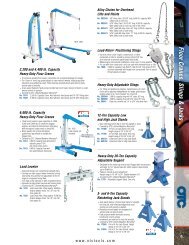
Data Link Connector (DLC) Pins<br />
1 - Manufacturer Reserved<br />
2 - J1850 Bus+<br />
3 - Manufacturer Reserved<br />
4 - Chassis Ground<br />
5 - Signal Ground<br />
6 - CAN High, J-2284<br />
7 - K Line, ISO 9141-2 & ISO/DIS 14230-4<br />
8 - Manufacturer Reserved<br />
9 - Manufacturer Reserved<br />
10 - J1850 Bus-<br />
11 - Manufacturer Reserved<br />
12 - Manufacturer Reserved<br />
13 - Manufacturer Reserved<br />
14 - CAN Low, J-2284<br />
15 - L Line, ISO 9141-2 & ISO/DIS 14230-4<br />
16 - Battery Power<br />
2 – 4 • • • • • • • • • • • • • • • • • • • • • • • • • • • • • • • • • • • • • • • • • • • • • • • • • • • • • • • •<br />
1<br />
9<br />
8<br />
16
Getting Started<br />
Vehicle Service Information<br />
The following is a list of web sites and phone numbers where diagnostic<br />
information is available. Some manuals may be available at your local<br />
dealer, auto parts stores, or local public libraries.<br />
Domestic Vehicles<br />
General Motors<br />
Web Site Phone Number<br />
Chevrolet www.chevrolet.com 1-800-551-4123<br />
Pontiac www.pontiac.com 1-800-551-4123<br />
Oldsmobile www.oldsmobile.com 1-800-551-4123<br />
Buick www.buick.com 1-800-551-4123<br />
Cadillac www.cadillac.com 1-800-333-4CAD<br />
Saturn<br />
Ford<br />
www.saturn.com 1-800-553-6000<br />
Ford www.ford.com 1-800-392-3673<br />
Lincoln www.lincoln.com 1-800-392-3673<br />
Mercury<br />
Chrysler<br />
www.mercury.com 1-800-392-3673<br />
Chrysler www.chrysler.com 1-800-348-4696<br />
Dodge www.dodge.com 1-800-348-4696<br />
Plymouth Not Available 1-800-348-4696<br />
Eagle Not Available 1-800-348-4696<br />
Other Manuals<br />
Chilton Book Company www.chiltonsonline.com 1-800-347-7707<br />
Haynes Publications www.haynes.com 1-800-242-4637<br />
Bentley Publishers www.bentleypublishers.com 1-800-423-4595<br />
Repair Information Programs<br />
Mitchell www.mitchell1.com 1-888-724-6742<br />
ALLDATA www.alldata.com 1-800-697-2533<br />
• • • • • • • • • • • • • • • • • • • • • • • • • • • • • • • • • • • • • • • • • • • • • • • • • • • • • • • • • 2 – 5<br />
2
2<br />
Getting Started<br />
2 – 6 • • • • • • • • • • • • • • • • • • • • • • • • • • • • • • • • • • • • • • • • • • • • • • • • • • • • • • • •
The <strong>Tool</strong><br />
Using the <strong>Tool</strong><br />
Section 3 – Using the <strong>Tool</strong><br />
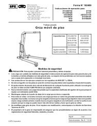
1 LCD Display - Backlit, 128 x 64 pixel display with contrast adjustment.<br />
2 / LEFT/RIGHT and / UP/DOWN arrow keys - Moves the cursor to<br />
3<br />
select functions or to select YES or NO.<br />
ENTER key - Selects displayed items.<br />
4 BACK key - Goes to the previous screen or level.<br />
5 USER key - allows the operator to perform Read <strong>Code</strong>s with a touch of<br />
a key.<br />
6 ON/OFF - turns the <strong>Tool</strong> power ON or OFF.<br />
7 DLC Port - Provides a connection for interfacing with the vehicle.<br />
8 USB Port - Provides a USB connection to the computer.<br />
9 Serial Number Decal - Provides serial number of the <strong>Tool</strong>.<br />
10 Battery Compartment - Provides power to the <strong>Tool</strong> when reprogramming<br />
the <strong>Tool</strong> or printing from a personal computer or for off-vehicle use such as<br />
reviewing of codes, code lookup, and system setup. (Battery not required<br />
to use <strong>Tool</strong> for reading codes.)<br />
7<br />
8<br />
2<br />
3 4<br />
6 5<br />
9 10<br />
• • • • • • • • • • • • • • • • • • • • • • • • • • • • • • • • • • • • • • • • • • • • • • • • • • • • • • • • • 3 – 1<br />
1<br />
3
3<br />
Using the <strong>Tool</strong><br />
Specifications<br />
✓ A minimum of 8.0 V is required for most vehicle control modules to operate<br />
properly.<br />
Power Dissipation: 5 Watts maximum.<br />
Dimensions: Height × Width × Length<br />
Included with the <strong>Tool</strong><br />
Table 1: Specifications<br />
Display: 128 x 64 pixel display with contrast adjust<br />
Operating Temperature: 0 to 50 0<br />
C (32 to 122 0<br />
F)<br />
Storage Temperature: -20 to 70 0<br />
C (-4 to 158 0<br />
F)<br />
Internal Power: 9V Battery (not required to read codes)<br />
External Power: 7 to 16 Volts<br />
7/8” (22.56 mm) × 3.50” (89 mm) × 8.25” (210 mm)<br />
Table 2: Package Contents<br />
Part Part Description Part Number<br />
Vehicle Diagnostics Provides a link between the vehicle<br />
Cable and <strong>Tool</strong> so the <strong>Tool</strong> can communicate<br />
with the vehicle. Also supplies<br />
power to the <strong>Tool</strong>.<br />
0038-000-3458<br />
Carry Case Place to store the <strong>Tool</strong> when not in<br />
use.<br />
Quick Start Manual Provides basic step-by-step instructions<br />
for using the <strong>Tool</strong>.<br />
0400-000-2080<br />
0002-000-3142<br />
✓ Replacement Parts are available from the manufacturer by contacting customer<br />
service at 1-800-533-6127 (8:00 - 6:00 CST Monday - Friday)<br />
Display<br />
The display has a large viewing area for posting messages,<br />
instructions, and diagnostic information. The back-lit liquid crystal<br />
display (LCD) is a 128 x 64 pixel display.<br />
The following symbols may appear on the display. The chart below<br />
describes what each symbol means:<br />
Indicates that additional information is available on the<br />
previous screen. Press the UP arrow key to view the data.<br />
3 – 2 • • • • • • • • • • • • • • • • • • • • • • • • • • • • • • • • • • • • • • • • • • • • • • • • • • • • • • • •
Keypad<br />
Using the <strong>Tool</strong><br />
Indicates that additional information is available on the next<br />
screen. Press the DOWN arrow key to view the data.<br />
Indicates that the internal battery needs replacing or is not<br />
installed. Replace or install the internal battery.<br />
Indicates that the<br />
to read codes.<br />
USER key is active. Press the USER key<br />
The keypad is used to move through the different menus of the <strong>Tool</strong>.<br />
The <strong>Tool</strong> is designed for easy operation with an intuitive navigation<br />
system.<br />
! CAUTION<br />
! CAUTION<br />
C0023<br />
Left Front Wheel<br />
Speed Sensor Circuit<br />
Malfunction<br />
Current<br />
1 of 3<br />
<strong>ABS</strong><br />
Do not use solvents such as alcohol to clean the keypad<br />
or display. Use a mild nonabrasive detergent and a soft<br />
cotton cloth.<br />
Do not soak the keypad in water because the water<br />
might find its way inside the <strong>Tool</strong>.<br />
• • • • • • • • • • • • • • • • • • • • • • • • • • • • • • • • • • • • • • • • • • • • • • • • • • • • • • • • • 3 – 3<br />
�<br />
�<br />
3
3<br />
Using the <strong>Tool</strong><br />
<strong>Tool</strong> Power Up<br />
Power for the <strong>Tool</strong> can come from the vehicle or an internal 9V battery.<br />
All functions work when the <strong>Tool</strong> is<br />
connected to the car. The Review Data,<br />
Print Data, <strong>Code</strong> Lookup, and System<br />
Setup functions will also work on internal<br />
battery power.<br />
Vehicle Power<br />
The <strong>Tool</strong> will automatically turn on when connected to the vehicle.<br />
1. Connect the Vehicle Diagnostics Cable to the <strong>Tool</strong>.<br />
2. Connect the other end of the Vehicle Diagnostics Cable to the DLC<br />
on the vehicle.<br />
The <strong>Tool</strong> receives power from the vehicle when the Vehicle Diagnostics<br />
Cable is plugged into the vehicle DLC. If there are power up problems,<br />
see “<strong>Tool</strong> Does Not Power Up” on page 5-1.<br />
Internal Battery<br />
The ON/OFF key turns the <strong>Tool</strong> ON and<br />
OFF when operating on battery power.<br />
❒ Press and hold the ON/OFF key for at<br />
least 1 second to turn the <strong>Tool</strong> on or<br />
off.<br />
The <strong>Tool</strong> will automatically turn off after 2<br />
minutes of inactivity when powered from the<br />
internal 9V battery.<br />
When powered from the internal battery, the<br />
<strong>Tool</strong> turns off the backlighting for the display if no key presses are made<br />
during a 1-minute period.<br />
If a key is pressed prior to the <strong>Tool</strong> powering off, the backlighting for the<br />
display will turn back on.<br />
The <strong>Tool</strong> must be attached to the vehicle to perform diagnostic<br />
functions. The <strong>Tool</strong> disables the diagnostic functions when powered<br />
from the internal battery.<br />
Each time the <strong>Tool</strong> is powered up, the voltage of the internal battery is<br />
checked.<br />
• If the voltage is low, the Low Battery Symbol displays on the<br />
screen.<br />
• Replace the battery using instructions provided in “Battery Replacement”<br />
on page 5-2.<br />
3 – 4 • • • • • • • • • • • • • • • • • • • • • • • • • • • • • • • • • • • • • • • • • • • • • • • • • • • • • • • •
! CAUTION<br />
User Key<br />
Using the <strong>Tool</strong><br />
If the <strong>Tool</strong> will not be used for an extended period of time,<br />
remove the battery to prevent battery leakage from damaging<br />
the battery compartment.<br />
The USER key allows you to read codes from the Diagnostic menu<br />
without having to select Read <strong>Code</strong>s. Press the<br />
or read codes from the vehicle.<br />
USER key to update<br />
• When the USER key is active, the icon appears on the display.<br />
• When the<br />
USER key.<br />
appears, you can perform read codes by pressing the<br />
• The USER key remains inactive until a vehicle has been selected.<br />
Note: The USER key is not active when the <strong>Tool</strong> is powered from the<br />
internal 9V battery.<br />
Installing <strong>Scan</strong>ning Suite<br />
1. Go to www.otctools.com/updates and download the <strong>Scan</strong>ning<br />
Suite PC application.<br />
✓ <strong>Scan</strong>ning Suite is NOT required to operate the <strong>Scan</strong> <strong>Tool</strong>.<br />
2. Install the downloaded <strong>Scan</strong>ning Suite application prior to<br />
connecting the <strong>Scan</strong> <strong>Tool</strong> to the PC.<br />
Some of the items included in <strong>Scan</strong>ning Suite are:<br />
• Manuals included with <strong>Scan</strong> <strong>Tool</strong><br />
• <strong>Tool</strong> update software<br />
• Adobe Acrobat <strong>Reader</strong> Installer<br />
• Print Capture<br />
• Other product information<br />
To be able to use <strong>Scan</strong>ning Suite, the PC must meet the following<br />
minimum requirements:<br />
• Microsoft Windows 2000, XP, and Vista<br />
• Adobe Acrobat <strong>Reader</strong><br />
• Internet Explorer 4.0 or newer<br />
• Screen Resolution of 800 X 600<br />
• • • • • • • • • • • • • • • • • • • • • • • • • • • • • • • • • • • • • • • • • • • • • • • • • • • • • • • • • 3 – 5<br />
3
3<br />
Using the <strong>Tool</strong><br />
3. If screen resolution is 800 x 600, in Display Properties, Settings<br />
Tab, set Font Size to Small Fonts.<br />
4. Use <strong>Scan</strong>ning Suite to determine if any updates are available for<br />
your tool by clicking Check for Update button.<br />
✓ You can also configure the <strong>Scan</strong>ning Suite Frequency (SS Frequency) to<br />
automatically check every xx minutes. The default frequency is 30 minutes.<br />
5. Refer to instructions provided on www.otctools.com/updates for<br />
how to install <strong>Scan</strong>ning Suite and <strong>Tool</strong> updates.<br />
System Setup<br />
System Setup allows you to:<br />
• Adjust Contrast<br />
• Select Language<br />
• Test the Display<br />
• Test the Keypad<br />
• Test the Memory<br />
• View <strong>Tool</strong> Information<br />
• Reprogram the <strong>Tool</strong><br />
✓ System Setup settings are retained even if the internal battery<br />
becomes discharged or is removed.<br />
From the Main Menu:<br />
1. Select System Setup.<br />
2. Press the UP or DOWN arrow key<br />
until System Setup is highlighted.<br />
3. Press ENTER.<br />
MAIN MENU<br />
==========================<br />
Vehicle Diagnostics<br />
Review<br />
Print Data<br />
System Setup<br />
3 – 6 • • • • • • • • • • • • • • • • • • • • • • • • • • • • • • • • • • • • • • • • • • • • • • • • • • • • • • • •
Adjust Display Contrast<br />
From the System Setup menu:<br />
1. Select Adjust Contrast.<br />
a. Press the UP or DOWN arrow<br />
key until Adjust Contrast is<br />
highlighted.<br />
b. Press ENTER.<br />
2. Adjust Display Contrast.<br />
a. Press the UP arrow key to<br />
darken.<br />
b. Press the DOWN arrow key to<br />
lighten.<br />
3. To save the Contrast setting,<br />
press ENTER.<br />
Using the <strong>Tool</strong><br />
SYSTEM SETUP<br />
=========================<br />
Adjust Contrast<br />
Language Setup<br />
Display Test<br />
Keypad Test<br />
Memory Test<br />
�<br />
<strong>Tool</strong> Information �<br />
ADJUST CONTRAST<br />
==========================<br />
Darken<br />
�Lighten<br />
Press ENTER<br />
when Done<br />
50%<br />
• • • • • • • • • • • • • • • • • • • • • • • • • • • • • • • • • • • • • • • • • • • • • • • • • • • • • • • • • 3 – 7<br />
�<br />
�<br />
3
3<br />
Using the <strong>Tool</strong><br />
Language Setup<br />
Language Setup is used to change the language used by the <strong>Tool</strong>.<br />
✓ English is the default language.<br />
From System Setup menu:<br />
1. Choose Language Setup.<br />
a. Use UP or DOWN arrow key<br />
to highlight Language Setup.<br />
b. Press ENTER.<br />
2. Select Desired Language.<br />
•Use UP or DOWN arrow key<br />
to highlight desired language.<br />
3. To save Language Setting,<br />
press ENTER.<br />
Or,<br />
4. To keep the old setting and<br />
return to the Main Menu, press<br />
the BACK key.<br />
SYSTEM SETUP<br />
=========================<br />
Adjust Contrast<br />
Language Setup<br />
Display Test<br />
Keypad Test<br />
Memory Test<br />
�<br />
<strong>Tool</strong> Information �<br />
Language Setup<br />
=========================<br />
English<br />
Espanol<br />
3 – 8 • • • • • • • • • • • • • • • • • • • • • • • • • • • • • • • • • • • • • • • • • • • • • • • • • • • • • • • •
Display Test<br />
The Display Test is used to check the display.<br />
✓ The test turns on every pixel of the display.<br />
From the System Setup menu:<br />
1. Select Display Test.<br />
• Press the UP or DOWN arrow<br />
key until Display Test is highlighted.<br />
2. To start Display Test, press ENTER.<br />
3. Look for Missing Pixels.<br />
• All pixels display in solid black if there are no concerns.<br />
• Screen flips back and forth between screens shown below.<br />
4. To return to System Setup,<br />
press the BACK Key.<br />
Using the <strong>Tool</strong><br />
SYSTEM SETUP<br />
=========================<br />
Adjust Contrast<br />
Language Setup<br />
Display Test<br />
Keypad Test<br />
Memory Test<br />
�<br />
<strong>Tool</strong> Information<br />
Display Test<br />
Check for Missing<br />
Spots in Display<br />
Press Back �<br />
to Quit<br />
• • • • • • • • • • • • • • • • • • • • • • • • • • • • • • • • • • • • • • • • • • • • • • • • • • • • • • • • • 3 – 9<br />
3
3<br />
Using the <strong>Tool</strong><br />
Keypad Test<br />
The Keypad Test is used to verify that<br />
the keys are working correctly.<br />
From the System Setup menu:<br />
1. Select Keypad Test.<br />
a. Press the UP or DOWN arrow<br />
key until Keypad Test is<br />
highlighted.<br />
b. Press ENTER.<br />
2. Press a Key.<br />
• Key name or scroll direction should<br />
inverse colors on the display.<br />
• The only exception is the BACK<br />
key. When BACK key is<br />
pressed, the System Setup<br />
menu appears.<br />
Note: If the System Setup menu<br />
does not appear, then the<br />
BACK key is not working correctly.<br />
Contact Technical Support<br />
for assistance. The phone number<br />
for Technical Support is provided<br />
on the back side of the title<br />
page.<br />
SYSTEM SETUP<br />
=========================<br />
Adjust Contrast<br />
Language Setup<br />
Display Test<br />
Keypad Test<br />
Memory Test<br />
�<br />
<strong>Tool</strong> Information �<br />
Keypad Test<br />
=========================<br />
ENTER<br />
BACK<br />
UP<br />
LEFT⊳<br />
RIGHT �<br />
DOWN<br />
POWER USER<br />
Press BACK to Quit<br />
3 – 10 • • • • • • • • • • • • • • • • • • • • • • • • • • • • • • • • • • • • • • • • • • • • • • • • • • • • • • •<br />
�<br />
�<br />
�<br />
�
Memory Test<br />
Using the <strong>Tool</strong><br />
The Memory Test will test the <strong>Tool</strong>’s internal memory. Run the Memory<br />
Test if the <strong>Tool</strong>:<br />
• Has trouble displaying trouble code definitions.<br />
• Operates abnormally.<br />
From the System Setup menu:<br />
1. Select Memory Test.<br />
a. Press the UP or DOWN arrow<br />
key until Memory Test is<br />
highlighted.<br />
b. Press ENTER.<br />
✓ The <strong>Tool</strong> reports its progress on the<br />
bottom of the display.<br />
❒ The Memory Test may take<br />
several minutes to complete.<br />
❒ The Memory Test results display:<br />
• If no problems were<br />
detected, then PASS is displayed.<br />
• If RAM fails, an error message<br />
is shown.<br />
• If ROM fails, a checksum is<br />
shown.<br />
• If the Memory Test fails,<br />
contact Technical Support.<br />
The phone number for Technical<br />
Support is provided on<br />
the back side of the title page.<br />
2. To return to System Setup,<br />
press BACK.<br />
SYSTEM SETUP<br />
=========================<br />
Adjust Contrast<br />
Language Setup<br />
Display Test<br />
Keypad Test<br />
Memory Test<br />
�<br />
<strong>Tool</strong> Information �<br />
Memory Test<br />
=========================<br />
RAM: Pass<br />
ROM: Pass<br />
EEPROM: Pass<br />
Press BACK �<br />
to Cont<br />
• • • • • • • • • • • • • • • • • • • • • • • • • • • • • • • • • • • • • • • • • • • • • • • • • • • • • • • • 3 – 11<br />
3
3<br />
Using the <strong>Tool</strong><br />
View <strong>Tool</strong> Information<br />
This function allows you to view specific <strong>Tool</strong> information that may be<br />
needed when contacting customer service.<br />
From System Setup menu:<br />
1. Select <strong>Tool</strong> Information.<br />
a. Press the UP or DOWN arrow<br />
key until <strong>Tool</strong> Information is<br />
highlighted.<br />
b. Press ENTER.<br />
2. View the <strong>Tool</strong> Information.<br />
• S/N (Serial No:)<br />
• Software ID (SW ID:)<br />
3. Write Down the <strong>Tool</strong><br />
Information.<br />
• Space is provided on inside front<br />
cover of this guide to record the<br />
<strong>Tool</strong> information.<br />
4. To return to System Setup,<br />
press BACK.<br />
Program Mode<br />
The Program Mode is used to<br />
reprogram the <strong>Tool</strong>. Instructions are<br />
provided with the software upgrades.<br />
SYSTEM SETUP<br />
=========================<br />
Adjust Contrast<br />
Language Setup<br />
Display Test<br />
Keypad Test<br />
Memory Test<br />
�<br />
<strong>Tool</strong> Information �<br />
<strong>Tool</strong> Information<br />
=========================<br />
S/N: 1234567<br />
SWID: A7B1<br />
Press BACK � to Exit<br />
SYSTEM SETUP<br />
=========================<br />
Language Setup ��<br />
Display Test<br />
Keypad Test<br />
Memory Test<br />
<strong>Tool</strong> Information<br />
Program Mode<br />
3 – 12 • • • • • • • • • • • • • • • • • • • • • • • • • • • • • • • • • • • • • • • • • • • • • • • • • • • • • • •
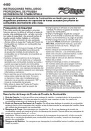
Connecting the <strong>Tool</strong><br />
Using the <strong>Tool</strong><br />
To diagnose a vehicle, connect the Vehicle Diagnostics Cable to the<br />
<strong>Tool</strong>.<br />
Tip: If you just want to power up the <strong>Tool</strong> to review data, lookup codes,<br />
or print the data from the last vehicle tested, then you do not need to<br />
attach the Vehicle Diagnostics Cable to the vehicle. The internal battery<br />
provides power for this.<br />
1. Connect the Vehicle Diagnostics<br />
Cable to the <strong>Tool</strong>.<br />
• Make sure the pins on the cable are<br />
not bent.<br />
2. Find the DLC on the<br />
vehicle.<br />
• Look under the dashboard<br />
on the driver’s side of the<br />
vehicle.<br />
• If the DLC is not located<br />
under the dashboard, a<br />
label should be there telling<br />
you where it is located.<br />
3. Remove the DLC cover if<br />
required.<br />
4. Connect the Vehicle<br />
Diagnostics Cable to<br />
vehicle.<br />
• Make sure the pins are not bent.<br />
• • • • • • • • • • • • • • • • • • • • • • • • • • • • • • • • • • • • • • • • • • • • • • • • • • • • • • • • 3 – 13<br />
3
3<br />
Using the <strong>Tool</strong><br />
Vehicle Selection<br />
Selecting a vehicle is required to communicate with the vehicle and to<br />
correctly display DTC definitions. The <strong>Tool</strong> keeps all data received from<br />
the last vehicle selected until a new vehicle is selected or the <strong>Tool</strong> is<br />
reprogrammed to update software.<br />
During vehicle selection, the <strong>Tool</strong> may ask for the following information:<br />
• Manufacturer<br />
• Car/Truck<br />
• Year<br />
• Make<br />
• Model<br />
• Engine<br />
• Special Information<br />
From the Main Menu:<br />
1. Choose Vehicle Diagnostics.<br />
a. Press the UP or DOWN arrow<br />
key until Vehicle Diagnostics<br />
is highlighted.<br />
b. Press ENTER.<br />
2. Select to KEEP or CHANGE<br />
vehicle.<br />
• To run or review diagnostics on<br />
the same vehicle, press LEFT<br />
for YES. Continue these instructions<br />
with Step 3.<br />
• To run diagnostics on a different<br />
vehicle, press RIGHT for NO.<br />
Continue these instructions with<br />
Step 4.<br />
• If this is the first time that you are<br />
using the <strong>Tool</strong> or no vehicle identification<br />
information is stored in<br />
memory, the <strong>Tool</strong> will ask you to<br />
provide vehicle identification information.<br />
Go to Step 5 below to<br />
continue.<br />
MAIN MENU<br />
=========================<br />
Vehicle Diagnostics<br />
Review<br />
Print Data<br />
System Setup<br />
Confirm Selection<br />
2002 Sunfire<br />
2.2L<br />
Manual Transmission<br />
Keep This Vehicle?<br />
YES NO�<br />
⊳<br />
The vehicle identification information is used by the <strong>Tool</strong> to perform<br />
diagnostics. Enter or confirm vehicle identification information.<br />
3 – 14 • • • • • • • • • • • • • • • • • • • • • • • • • • • • • • • • • • • • • • • • • • • • • • • • • • • • • • •
3. Select to KEEP or ERASE<br />
diagnostic data.<br />
• To erase data stored from the previous<br />
vehicle test, press<br />
LEFT for YES. Then go to<br />
“Read <strong>Code</strong>s” on page 4-1 of<br />
Vehicle Diagnostics for instructions<br />
on running Vehicle Diagnostics.<br />
• To keep the existing diagnostic<br />
data to review, press RIGHT<br />
for NO. Then go to “Review Data”<br />
in Vehicle Diagnotistics.<br />
4. Select New Vehicle?<br />
• To erase the data stored on the<br />
<strong>Tool</strong>, press LEFT for YES.<br />
Then go to Step 5 to enter the<br />
new vehicle identification information.<br />
• To keep the data stored in the<br />
<strong>Tool</strong>, press RIGHT for NO.<br />
Then repeat these instructions<br />
from Step 2.<br />
5. Select Vehicle.<br />
a. Press the UP or DOWN arrow<br />
key to select vehicle.<br />
b. Press ENTER.<br />
6. Select Vehicle Manufacturer.<br />
a. Press the UP or DOWN arrow<br />
key to select vehicle<br />
manufacturer.<br />
b. Press ENTER.<br />
Do You Want to<br />
Erase Data Stored<br />
In the <strong>Tool</strong> From<br />
the Previous<br />
Vehicle Tests?<br />
⊳ YES NO �<br />
Selecting a New<br />
Vehicle Erases Data<br />
Stored in the <strong>Tool</strong><br />
From the Previous<br />
Vehicle Tests!<br />
Continue?<br />
⊳ YES NO�<br />
Using the <strong>Tool</strong><br />
SELECT VEHICLE<br />
==========================<br />
Global <strong>OBDII</strong><br />
Domestic Vehicles<br />
European Vehicles<br />
Asian Vehicles<br />
Select Manufacturer<br />
==========================<br />
Global <strong>OBDII</strong><br />
General Motors<br />
Ford<br />
Chrysler<br />
• • • • • • • • • • • • • • • • • • • • • • • • • • • • • • • • • • • • • • • • • • • • • • • • • • • • • • • • 3 – 15<br />
3
3<br />
Using the <strong>Tool</strong><br />
7. Select the Vehicle Type.<br />
a. Press the UP or DOWN arrow<br />
key to select vehicle type.<br />
b. Press ENTER.<br />
8. Select the Year.<br />
a. Press the UP or DOWN arrow<br />
key to select the Year.<br />
b. Press ENTER.<br />
9. Select the Make.<br />
a. Press the UP or DOWN arrow<br />
key to select the Make.<br />
b. Press ENTER.<br />
10. Select the Model.<br />
a. Press the UP or DOWN arrow<br />
key to select the Model.<br />
b. Press ENTER.<br />
11. Select the Engine.<br />
a. Press the UP or DOWN<br />
arrow key to select the Engine.<br />
b. Press ENTER.<br />
Select Vehicle Type<br />
==========================<br />
Car<br />
Truck<br />
Select Year<br />
==========================<br />
2009 and Newer<br />
2008<br />
2007<br />
2006<br />
2005<br />
2004<br />
Select Make<br />
=========================<br />
Global <strong>OBDII</strong><br />
Buick<br />
Cadillac<br />
Chevrolet<br />
Pontiac<br />
Saturn<br />
Select Model<br />
==========================<br />
Global <strong>OBDII</strong><br />
Aveo<br />
Aveo5<br />
Cobalt<br />
Corvette<br />
HHR<br />
Select Engine VIN 6<br />
===========================<br />
Global <strong>OBDII</strong><br />
X = 2.0<br />
D = 2.2<br />
P = 2.4<br />
✓ In some instances, the vehicle information applies to all but a few engine<br />
sizes.<br />
✓ When provided, select the exact engine size, otherwise select Global<br />
<strong>OBDII</strong>.<br />
3 – 16 • • • • • • • • • • • • • • • • • • • • • • • • • • • • • • • • • • • • • • • • • • • • • • • • • • • • • • •
Using the <strong>Tool</strong><br />
✓ If a specific engine size is selected, you may also need to select additional<br />
information (called Special). If Special information is required to identify the<br />
<strong>ABS</strong> system, go to Step 12 to continue these instructions.<br />
12. Confirm Selections.<br />
• Press LEFT for YES.<br />
• Press RIGHT for NO.<br />
✓ If YES is selected, the <strong>Tool</strong> confirms the vehicle information and then goes<br />
to Step 13.<br />
✓ If NO is selected, the <strong>Tool</strong> returns to the Select Manufacturer screen.<br />
Repeat these instructions from Step 5.<br />
If the <strong>Tool</strong> is capable of supporting <strong>ABS</strong> or <strong>SRS</strong> of the selected vehicle,<br />
you will be prompted to confirm <strong>ABS</strong> or <strong>SRS</strong> availability.<br />
13. Confirm <strong>ABS</strong> Availablility.<br />
• Press LEFT for YES.<br />
• Press RIGHT for NO.<br />
14. Confirm <strong>SRS</strong> Availablility.<br />
• Press LEFT for YES.<br />
• Press RIGHT for NO.<br />
Global <strong>OBDII</strong><br />
Keep This Vehicle?<br />
⊳ YES NO �<br />
<strong>ABS</strong> Confirmation<br />
�������������������������������<br />
Is the vehicle<br />
equipped with <strong>ABS</strong>?<br />
�YES NO�<br />
Airbag Confirmation<br />
�������������������������������<br />
Is the vehicle<br />
equipped with <strong>SRS</strong>?<br />
�YES NO�<br />
✓ Following Vehicle Selection, tool goes to the Diagnostic Menu. See Section<br />
4 - Vehicle Diagnostics for instructions.<br />
• • • • • • • • • • • • • • • • • • • • • • • • • • • • • • • • • • • • • • • • • • • • • • • • • • • • • • • • 3 – 17<br />
3
3<br />
Using the <strong>Tool</strong><br />
3 – 18 • • • • • • • • • • • • • • • • • • • • • • • • • • • • • • • • • • • • • • • • • • • • • • • • • • • • • • •
Vehicle Diagnostics<br />
Section 4 – Vehicle Diagnostics<br />
Diagnostic Menu<br />
From the Diagnostic Menu, you can:<br />
• Read <strong>Code</strong>s<br />
• Erase <strong>Code</strong>s<br />
• MIL Status<br />
• I/M Monitors<br />
• View Data<br />
• View Freeze Data<br />
• Review<br />
• Print Data<br />
• <strong>Code</strong> Lookup<br />
• System Setup<br />
The <strong>Tool</strong> keeps all data received from the last vehicle selected until any<br />
of the following occurs:<br />
• The <strong>Tool</strong> is reprogrammed to update software.<br />
• A new vehicle is selected.<br />
Read <strong>Code</strong>s<br />
DIAGNOSTIC MENU<br />
==============================<br />
Read <strong>Code</strong>s<br />
Erase <strong>Code</strong>s<br />
MIL Status<br />
I/M Monitor<br />
View Data<br />
�<br />
View Freeze Data<br />
The Read <strong>Code</strong>s function allows the <strong>Tool</strong> to read the diagnostic trouble<br />
codes (DTCs) from the vehicle control modules. DTCs are used to help<br />
determine the cause of a problem or problems with a vehicle. The<br />
anti-lock brake control module reports DTCs pertaining to the brake<br />
system.<br />
Read <strong>Code</strong>s can be done with the Key On Engine Off (KOEO) or with<br />
the Key On Engine Running (KOER).<br />
If no DTCs are present, a message stating Pass: No <strong>Code</strong>s Found is<br />
displayed.<br />
To access the Diagnostic Menu, select Vehicle Diagnostics from the<br />
Main Menu and select a vehicle.<br />
When codes are viewed, the <strong>Tool</strong> displays Diagnostic Trouble <strong>Code</strong>s<br />
(DTCs). DTCs are reported when a component, sensor, or other part of<br />
the vehicle is indicating a malfunction is present. The malfunction must<br />
be present for a sufficient amount of time before the <strong>Tool</strong> will display a<br />
Confirmed Trouble <strong>Code</strong>.<br />
• • • • • • • • • • • • • • • • • • • • • • • • • • • • • • • • • • • • • • • • • • • • • • • • • • • • • • • • • 4 – 1<br />
4
4<br />
Vehicle Diagnostics<br />
Pending <strong>Code</strong>s are only reported if a problem occurs during the current<br />
or last completed drive cycle. Pending <strong>Code</strong>s do not necessarily<br />
indicate a faulty component or system. Pending <strong>Code</strong>s convert to<br />
Confirmed Trouble <strong>Code</strong>s when an emissions problem persists long<br />
enough to be considered a real problem, ont an anomaly. Pending<br />
<strong>Code</strong>s are indicated with a PENDING descriptor.<br />
From the Diagnostic Menu:<br />
1. Select Read <strong>Code</strong>s.<br />
a. Press the UP or DOWN<br />
arrow key until Read <strong>Code</strong>s is<br />
highlighted.<br />
b. Press ENTER.<br />
2. Select Module.<br />
If the <strong>Tool</strong> supports <strong>ABS</strong> and <strong>SRS</strong> for<br />
the user selected vehicle, the Select<br />
Module menu is shown. If no menu is<br />
shown, only Global <strong>OBDII</strong> codes are<br />
read.<br />
a. Press the UP or DOWN<br />
arrow key to highlight module.<br />
b. Press ENTER.<br />
Note: When the symbol appears on the display, you can read codes<br />
by pressing the User key.<br />
If an Error message displays, make sure the vehicle diagnostics cable<br />
is attached. Turn the ignition key off for 10 seconds, then on. (This may<br />
be required to reset the vehicle computer. If the problem still exists, see<br />
“Error Messages” on page 5-1.)<br />
3. View diagnostic results and<br />
write down the DTCs.<br />
Four possible results can occur:<br />
a. If the information returned by<br />
the vehicle does not match the<br />
vehicle selected, you may get<br />
an Unexpected Results<br />
message.<br />
����DIAGNOSTIC MENU<br />
������������������������������<br />
Read <strong>Code</strong>s<br />
Erase <strong>Code</strong>s<br />
MIL Status<br />
I/M Monitor<br />
View Data<br />
View Freeze Data<br />
Select Module<br />
==========================<br />
<strong>ABS</strong><br />
Airbag<br />
Global <strong>OBDII</strong><br />
Unexpected Results<br />
=========================<br />
DTCs may be present<br />
No definitions<br />
found. Verify<br />
selected vehicle<br />
is correct.<br />
Press ENTER to cont.<br />
4 – 2 • • • • • • • • • • • • • • • • • • • • • • • • • • • • • • • • • • • • • • • • • • • • • • • • • • • • • • • •<br />
�<br />
�
Vehicle Diagnostics<br />
• To return to the Diagnostic Menu, press ENTER.<br />
• To examine the selected vehicle.<br />
information stored in the <strong>Tool</strong>,<br />
press BACK to return to the<br />
Main Menu and then select Vehicle<br />
Diagnostics.<br />
b. If the <strong>Tool</strong> is unable to display a<br />
definition for all the DTCs<br />
returned by the vehicle, you<br />
may get an Unexpected Results<br />
- No definitions found for some<br />
DTCs error message.<br />
• To view the DTCs, press ENTER.<br />
• Press the UP or DOWN<br />
arrow keys to scroll through the DTCs.<br />
c. If no codes are found, a<br />
message appears indicating<br />
that No <strong>Code</strong>s were Found.<br />
d. If DTCs are found, the code<br />
and a definition will appear. For<br />
more information about the<br />
structure of the DTCs, see<br />
“Understanding DTCs” on page A-1.<br />
Press BACK �to cont.<br />
• Press the UP or DOWN arrow keys to scroll through the DTCs.<br />
4. To return to the Diagnostic Menu,<br />
press the BACK key.<br />
Note: On most vehicles, if you successfully<br />
repair the cause of the DTC, then the MIL<br />
should turn off after the vehicles successfully<br />
runs its self tests.<br />
Unexpected Results<br />
������������������������������<br />
No definitions found<br />
for some DTCs. DTCs<br />
shown may be wrong.<br />
Verify selected<br />
vehicle is correct.<br />
Press ENTER to cont.<br />
PASS<br />
No <strong>Code</strong>s Found<br />
• • • • • • • • • • • • • • • • • • • • • • • • • • • • • • • • • • • • • • • • • • • • • • • • • • • • • • • • • 4 – 3<br />
4
4<br />
Vehicle Diagnostics<br />
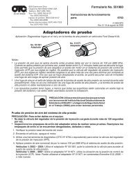
DTC Examples<br />
Several <strong>ABS</strong> DTC examples are shown below. <strong>SRS</strong> and Global <strong>OBDII</strong><br />
DTCs are presented similarly..<br />
DTC<br />
Definition<br />
DTC Status<br />
C0023<br />
Left Front Wheel<br />
Speed Sensor Circuit<br />
Malfunction<br />
Current<br />
General Motors provides additional information along with the DTCs:<br />
• Current - A current DTC indicates that a failure is currently present. A<br />
current code may have just occurred or may have been present over<br />
time.<br />
• History - A DTC with a History designation is one that has been<br />
detected by the anti-lock brake control module over a span of time. It<br />
is a current failure that has been present long enough to be stored in<br />
long-term memory.<br />
• CURR/HIST - A CURR/HIST DTC indicates that a failure is both current<br />
and historical as defined above.<br />
• Intermittent - An intermittent status indicates that the DTC has<br />
appeared intermittently since the anti-lock brake control module was<br />
reset. (Control modules are reset by mechanics after a repair has<br />
been completed.)<br />
This code indicates that you currently<br />
have a problem with the Left<br />
Front Wheel Speed Sensor Circuit<br />
and that the problem is illuminating<br />
the <strong>ABS</strong> malfunction indicator<br />
lamp (MIL) on the dashboard.<br />
This code indicates that you have<br />
had a problem with the Pump<br />
Motor Circuit long enough to be<br />
stored in long-term memory and<br />
that the problem is illuminating the<br />
<strong>ABS</strong> malfunction indicator lamp<br />
(MIL) on the dashboard. <strong>ABS</strong> systems<br />
rely on a pump to regulate<br />
brake fluid distribution.<br />
4 – 4 • • • • • • • • • • • • • • • • • • • • • • • • • • • • • • • • • • • • • • • • • • • • • • • • • • • • • • • •<br />
1 of 3<br />
<strong>ABS</strong><br />
�<br />
�<br />
Number of DTCs<br />
Vehicle Control Module<br />
Scroll Up key<br />
User key active<br />
Scroll Down key<br />
C0023<br />
Left Front Wheel<br />
Speed Sensor Circuit<br />
Malfunction<br />
Current<br />
C0110<br />
Pump Motor Circuit<br />
1 of 3<br />
<strong>ABS</strong><br />
2 of 3<br />
<strong>ABS</strong><br />
History MIL <strong>Code</strong><br />
�<br />
�<br />
�<br />
�
Erase <strong>Code</strong>s<br />
This code indicates that you have<br />
a current problem with the Network<br />
Bus Communication for the<br />
<strong>ABS</strong> controller and that the problem<br />
is illuminating the <strong>ABS</strong> malfunction<br />
indicator lamp (MIL) on<br />
the dashboard.<br />
Vehicle Diagnostics<br />
The Erase <strong>Code</strong>s function deletes DTC data from the control modules.<br />
Do not perform this function while the vehicle is in motion. The<br />
<strong>Tool</strong> must be connected to the vehicle to run this function.<br />
Perform Erase <strong>Code</strong>s function only after a system has been checked<br />
completely and the DTCs have been written down or printed.<br />
After servicing the vehicle, erase stored DTCs and verify that the codes<br />
have been cleared. If a DTC returns, the problem has not been fixed or<br />
other faults are present.<br />
The vehicle may need to be driven to conclude that a fault is repaired.<br />
From the Diagnostic Menu:<br />
1. Select Erase <strong>Code</strong>s.<br />
a. From the Diagnostic Menu,<br />
press the UP or DOWN<br />
arrow key until Erase <strong>Code</strong>s is<br />
highlighted.<br />
b. Press ENTER.<br />
If diagnostic results and codes are not<br />
to be erased, select No .<br />
• Selecting No takes you back<br />
to the Diagnostic Menu.<br />
2. Erase the diagnostic results<br />
and codes.<br />
• Press the LEFT arrow for Yes.<br />
U2100<br />
3 of 3<br />
<strong>ABS</strong><br />
Controller Area<br />
Network Bus<br />
�<br />
Communication<br />
�<br />
Current MIL <strong>Code</strong><br />
DIAGNOSTIC MENU<br />
��������������������������������<br />
Read <strong>Code</strong>s<br />
Erase <strong>Code</strong>s<br />
MIL Status<br />
I/M Monitors ��<br />
View Data<br />
View Freeze Data<br />
Erase?<br />
==========================<br />
Are you sure you<br />
want to Erase<br />
Diagnostic Results<br />
and <strong>Code</strong>s?<br />
�YES NO�<br />
WORKING<br />
Waiting for<br />
Vehicle to Respond<br />
Please Wait<br />
• • • • • • • • • • • • • • • • • • • • • • • • • • • • • • • • • • • • • • • • • • • • • • • • • • • • • • • • • 4 – 5<br />
�<br />
4
4<br />
Vehicle Diagnostics<br />
3. Select Module.<br />
If the <strong>Tool</strong> supports <strong>ABS</strong> and <strong>SRS</strong> for<br />
the user selected vehicle, the Select<br />
Module menu is shown. If no menu is<br />
shown, only Global <strong>OBDII</strong> codes are<br />
read.<br />
a. Press the UP or DOWN<br />
4.<br />
arrow key to highlight module.<br />
b. Press ENTER.<br />
Observe Command Sent message<br />
5. To return to the Diagnostic Menu,<br />
press BACK.<br />
MIL Status<br />
Malfunction Indicator Lamp (MIL) Status displays the state of the<br />
vehicles computer module(s). MIL Status is most useful if the engine<br />
is running. Some manufacturers turn the MIL off if a certain number of<br />
drive cycles occur without a fault.<br />
The computer’s memory erases Trouble <strong>Code</strong>s and resets MIL from<br />
memory if fault does not occur after 40 warm-up cycles.<br />
1.Select MIL Status.<br />
•Use UP or DOWN arrow key<br />
to highlight MIL Status.<br />
•Press ENTER.<br />
Select Module<br />
==========================<br />
<strong>ABS</strong><br />
Airbag<br />
Global <strong>OBDII</strong><br />
����DIAGNOSTIC MENU<br />
������������������������������<br />
Read <strong>Code</strong>s<br />
Erase <strong>Code</strong>s<br />
MIL Status<br />
I/M Monitor<br />
View Data<br />
View Freeze Data<br />
4 – 6 • • • • • • • • • • • • • • • • • • • • • • • • • • • • • • • • • • • • • • • • • • • • • • • • • • • • • • • •<br />
�
2. Review Results.<br />
����MIL is ON<br />
MIL Lamp Should<br />
be ON if<br />
Engine is Running<br />
Press BACK � to Exit<br />
OR<br />
3.Return to DIAGNOSTIC MENU.<br />
Press BACK.<br />
I/M Monitors (Emisson Systems)<br />
����MIL is OFF<br />
Vehicle Diagnostics<br />
MIL Lamp Should<br />
be OFF if<br />
Engine is Running<br />
Press BACK � to Exit<br />
The I/M Monitors (Inspection / Maintenance) function is used to view<br />
a snapshot of the operations for the Emission System on OBD II<br />
vehicles since the Diagnostic Trouble <strong>Code</strong>s were cleared.<br />
I/M Monitors is a very useful function. To guarantee no faults make sure<br />
all monitors are “ok” or “n/a” and no DTC’s exist.<br />
During normal driving conditions, the vehicle’s computer scans the<br />
emission system. After a specific amount of drive time (each monitor<br />
has specific driving conditions and time required), the computer’s<br />
"monitors" will decide if the vehicles emission system is working<br />
correctly or not as well as detecting out of range values. When the<br />
"monitor’s" status is:<br />
• "ok" - vehicle was driven enough to complete the monitor.<br />
• "inc" (Incomplete) - vehicle was not driven enough to complete the<br />
monitor.<br />
• "n/a" (Not Applicable) - vehicle does not support that monitor.<br />
Some states MAY NOT require all monitors listed to be ready to pass<br />
the emissions test. Check with state testing site for exact requirements.<br />
All states will fail a vehicle that has the MIL Light lit at time of test.<br />
Refer to the vehicles service manual for the drive cycle operation.<br />
Depending on vehicle, disconnecting or a discharged battery may<br />
erase trouble codes and clear monitor status. Clear Monitors by:<br />
• Erasing <strong>Code</strong>s.<br />
• Vehicle Computer Module losing power (on some vehicles.)<br />
• • • • • • • • • • • • • • • • • • • • • • • • • • • • • • • • • • • • • • • • • • • • • • • • • • • • • • • • • 4 – 7<br />
4
4<br />
Vehicle Diagnostics<br />
I/M Monitors function can be done with the Key On, Engine Running<br />
or Off.<br />
1.Select I/M Monitors.<br />
a. Use UP or DOWN arrow key<br />
to highlight I/M Monitors.<br />
b. Press ENTER.<br />
2.View Summary of Monitor<br />
Status.<br />
•Use UP or DOWN arrow<br />
key.<br />
����DIAGNOSTIC MENU<br />
������������������������������<br />
Read <strong>Code</strong>s<br />
Erase <strong>Code</strong>s<br />
MIL Status<br />
I/M Monitor<br />
View Data<br />
View Freeze Data<br />
��Since DTCs Cleared<br />
������������������������������<br />
Misfire Monitor ok<br />
Fuel System Mon ok<br />
Comp Component ok<br />
Catalyst Mon inc<br />
Htd Catalyst n/a<br />
Evap System Mon inc<br />
Abbreviate Name Expanded Name<br />
Misfire Monitor Misfire Monitor<br />
Fuel System Mon Fuel System Monitor<br />
Comp Component Comprehensive Components Monitor<br />
Catalyst Mon Catalyst Monitor<br />
Htd Catalyst Heated Catalyst Monitor<br />
Evap System Mon Evaporative System Monitor<br />
Sec Air System Secondary Air System Monitor<br />
A/C Refrig Mon Air Conditioning Refrigerant Monitor<br />
Oxygen Sens Mon Oxygen Sensor Monitor<br />
Oxygen Sens Htr Oxygen Sensor Heater Monitor<br />
EGR System Mon Exhaust Gas Recirculation System Monitor<br />
Two types of I/M Monitors tests are:<br />
Since DTCs Cleared - shows status of the monitors since the DTCs<br />
were last erased.<br />
This Drive Cycle - shows status of monitors since the start of the<br />
current drive cycle. Refer to the vehicle service manual for more<br />
detailed information on emission-related monitors and their status.<br />
✓ Some vehicles do not support This Drive Cycle. If vehicle supports both<br />
types of monitors the I/M Monitors Menu displays.<br />
4 – 8 • • • • • • • • • • • • • • • • • • • • • • • • • • • • • • • • • • • • • • • • • • • • • • • • • • • • • • • •<br />
�
View Data<br />
3.Return to DIAGNOSTIC MENU.<br />
• Press BACK.<br />
Vehicle Diagnostics<br />
The View Data function allows real time viewing of the vehicle computer<br />
module PID data. As the computer monitors the vehicle, information is<br />
simultaneously transmitted to the <strong>Tool</strong>.<br />
View Data allows these items to be viewed on the <strong>Tool</strong>:<br />
• Sensor data<br />
• Operation of switches<br />
• Operation of solenoids<br />
• Operation of relays<br />
Multiple PIDs may be sent if vehicle is equipped with more than one<br />
computer module. (for example a powertrain control module [PCM] and<br />
a transmission control module [TCM]. The <strong>Tool</strong> identifies them by their<br />
identification names (ID) assigned by the manufacturer (i.e. $10 or<br />
$1A).<br />
1. Select View Data.<br />
a. Use UP or DOWN arrow key<br />
to highlight View Data.<br />
b. Press ENTER.<br />
While data is collected, several<br />
screens show.<br />
2. View Data.<br />
����DIAGNOSTIC MENU<br />
������������������������������<br />
Read <strong>Code</strong>s<br />
Erase <strong>Code</strong>s<br />
MIL Status<br />
I/M Monitor<br />
View Data<br />
View Freeze Data<br />
MIL STATUS OFF<br />
<strong>ABS</strong>LT TPS % 100.0<br />
ENG SPEED RPM 0<br />
CALC LOAD % 0.0<br />
MAF FLOW GR/S 0.00<br />
COOLANT F -40<br />
IAT F -40<br />
IGN ADV DEG 0.0<br />
• • • • • • • • • • • • • • • • • • • • • • • • • • • • • • • • • • • • • • • • • • • • • • • • • • • • • • • • • 4 – 9<br />
�<br />
�<br />
4
4<br />
Vehicle Diagnostics<br />
3. To return to DIAGNOSTIC MENU,<br />
press BACK.<br />
View Freeze Data<br />
View Freeze Data is a “snapshot” of the operating conditions at the time<br />
of an emission-related fault. Faults with higher priority can overwrite<br />
View Freeze Data.<br />
Depending on when vehicle DTCs were last erased, Freeze Frame<br />
Data may not be stored in vehicles memory.<br />
1.Select View Freeze Data.<br />
a. Use UP or DOWN arrow key<br />
to highlight View Freeze Data.<br />
b. Press ENTER.<br />
While collecting data, several screens<br />
show.<br />
2. Select DTC (if more than 1<br />
DTC is present.)<br />
a. Use UP or DOWN arrow<br />
key to highlight desired frame.<br />
b. Press ENTER.<br />
3. View Freeze Data.<br />
DIAGNOSTIC MENU<br />
=========================<br />
Read <strong>Code</strong>s<br />
Erase <strong>Code</strong>s<br />
MIL Status<br />
I/M Monitors<br />
View Data �<br />
View Freeze Data<br />
Select Frame<br />
==========================<br />
Frame 1<br />
Frame 2<br />
Frame 1 Mod $10<br />
TROUB CODE P0686<br />
ENG SPEED RPM 4000<br />
CALC LOAD % 50<br />
COOLANT F 120<br />
VEH SPEED MPH 55<br />
4 – 10 • • • • • • • • • • • • • • • • • • • • • • • • • • • • • • • • • • • • • • • • • • • • • • • • • • • • • • •<br />
�
Review<br />
4.Select another frame to view (if<br />
available.)<br />
• Press BACK.<br />
5.To return to DIAGNOSTIC MENU,<br />
press BACK.<br />
Vehicle Diagnostics<br />
The Review function allows the user to view the data reported from the<br />
previous vehicle tested. Review has three types of data.<br />
• <strong>Code</strong>s<br />
• I/M Monitors<br />
• View Freeze Data<br />
You cannot review data until you have run the respective function. For<br />
instructions on running the Read <strong>Code</strong>s function, see “Read <strong>Code</strong>s” on<br />
page 4-1.<br />
The <strong>Tool</strong> does not require power from the vehicle to use the Review<br />
function.<br />
1. Select Review.<br />
The Review function is available from<br />
both the Main Menu and the Diagnostic<br />
Menu for your convenience.<br />
❒ To Review from the Main Menu:<br />
• From the Main Menu, press the<br />
UP or DOWN arrow key<br />
until Review Data is highlighted<br />
then press ENTER.<br />
Or,<br />
MAIN MENU<br />
=========================<br />
Vehicle Diagnostics<br />
Review<br />
Print Data<br />
System Setup<br />
• • • • • • • • • • • • • • • • • • • • • • • • • • • • • • • • • • • • • • • • • • • • • • • • • • • • • • • • 4 – 11<br />
4
4<br />
Vehicle Diagnostics<br />
❒ To Review from the Diagnostic<br />
Menu:<br />
• From the Main Menu, press the<br />
UP or DOWN arrow key<br />
until Vehicle Diagnostics is highlighted<br />
and then press ENTER.<br />
• When the Confirm Selection<br />
screen appears, press LEFT<br />
for Yes to keep the current vehicle.<br />
• Keep the existing data stored in<br />
the <strong>Tool</strong>, press RIGHT for No<br />
to continue.<br />
• From the Diagnostic Menu, use<br />
the arrow keys to highlight<br />
Review and then press ENTER.<br />
2. After selecting <strong>Code</strong>s, I/M<br />
Monitors, or View Freeze<br />
Frame, observe the data<br />
provided by the <strong>Tool</strong>.<br />
MAIN MENU<br />
=========================<br />
Vehicle Diagnostics<br />
Review<br />
Print Data<br />
System Setup<br />
Confirm Selection<br />
2002 Sunfire<br />
2.2L<br />
Manual Transmission<br />
Keep This Vehicle?<br />
YES NO<br />
⊳ �<br />
Do You Want to<br />
Erase Data Stored<br />
In the <strong>Tool</strong> From<br />
the Previous<br />
Vehicle Tests?<br />
⊳YES<br />
NO�<br />
DIAGNOSTIC MENU<br />
==========================<br />
Erase <strong>Code</strong>s<br />
MIL Status<br />
I/M Monitors<br />
View Data es<br />
View Freeze Data �<br />
Review<br />
4 – 12 • • • • • • • • • • • • • • • • • • • • • • • • • • • • • • • • • • • • • • • • • • • • • • • • • • • • • • •<br />
�
Press the UP or DOWN arrow key<br />
to review the data.<br />
If data does not exist, a message<br />
informs the user to run the Read <strong>Code</strong><br />
function before reviewing data.<br />
3. To return to the prior menu,<br />
press BACK.<br />
Print Data<br />
Vehicle Diagnostics<br />
No Data Stored In<br />
<strong>Tool</strong>. Read <strong>Code</strong>s<br />
Before Reviewing.<br />
Press BACK to Cont<br />
The Print Data function allows the printing of diagnostic information<br />
stored in the <strong>Tool</strong>.<br />
The <strong>Tool</strong>’s internal battery power can be used to print data.<br />
Print Data is available from both the Main Menu and Diagnostic<br />
Menu.<br />
To use the Print Data function, you must install the PC <strong>Scan</strong>ning Suite<br />
software found at www.otctools.com/updates. Launch the <strong>Scan</strong>ning<br />
Suite and then start the printing application.<br />
Follow all instructions on the PC.<br />
1. Connect the <strong>Tool</strong> to your PC.<br />
• Take the USB cable and attach the Mini B Connector to the<br />
Device Port on the <strong>Tool</strong>.<br />
• Attach the Host Connector to a USB Port on the personal computer<br />
(PC).<br />
• • • • • • • • • • • • • • • • • • • • • • • • • • • • • • • • • • • • • • • • • • • • • • • • • • • • • • • • 4 – 13<br />
�<br />
4
4<br />
Vehicle Diagnostics<br />
❒ To Print Data from the Main<br />
Menu:<br />
a. From the Main Menu, press<br />
the<br />
UP or DOWN arrow key<br />
until Print Data is<br />
highlighted.<br />
b. Press ENTER., and then go<br />
to Step 2.<br />
Or,<br />
❒ To Print Data from the<br />
Diagnostic Menu:<br />
a. From the Main Menu, press<br />
the UP or DOWN arrow<br />
key until Vehicle Diagnostics<br />
is highlighted.<br />
b. Press ENTER.<br />
2. When the Confirm Selection<br />
screen appears, press<br />
LEFT for Yes to keep the<br />
current vehicle.<br />
a. Keep the existing data<br />
stored in the <strong>Tool</strong>, press<br />
RIGHT for No to<br />
continue.<br />
MAIN MENU<br />
==========================<br />
Vehicle Diagnostics<br />
Review<br />
Print Data<br />
System Setup<br />
MAIN MENU<br />
=========================<br />
Vehicle Diagnostics<br />
Review<br />
Print Data<br />
System Setup<br />
Confirm Selection<br />
2002 Sunfire<br />
2.2L<br />
Manual Transmission<br />
Keep This Vehicle?<br />
YES NO<br />
⊳ �<br />
Do You Want to<br />
Erase Data Stored<br />
In the <strong>Tool</strong> From<br />
the Previous<br />
Vehicle Tests?<br />
⊳YES<br />
NO�<br />
4 – 14 • • • • • • • • • • • • • • • • • • • • • • • • • • • • • • • • • • • • • • • • • • • • • • • • • • • • • • •
. On the Diagnostic Menu,<br />
press the UP or DOWN<br />
arrow key until Print Data is<br />
highlighted.<br />
c. Press ENTER.<br />
3. Start the PC Printing application.<br />
• Follow the instructions on the personal<br />
computer.<br />
4. Send the data to the PC.<br />
• Press ENTER on the <strong>Tool</strong>.<br />
5. To return to the previous<br />
menu, press ENTER on the<br />
<strong>Tool</strong>.<br />
<strong>Code</strong> Lookup<br />
Vehicle Diagnostics<br />
<strong>Code</strong> Lookup accesses a library of possible DTCs for the selected<br />
vehicle. The <strong>Tool</strong> does not require power from the vehicle to perform<br />
this function. <strong>Code</strong> Lookup is only available from the Diagnostic Menu<br />
because the user must select a vehicle prior to accessing the library.<br />
From the Diagnostic Menu:<br />
1. Select <strong>Code</strong> Lookup.<br />
a. Press the UP or DOWN<br />
arrow key until <strong>Code</strong> Lookup is<br />
highlighted.<br />
b. Press ENTER.<br />
DIAGNOSTIC MENU<br />
===========================<br />
MIL Status<br />
�<br />
I/M Monitors<br />
View Data<br />
View Freeze Data<br />
Review<br />
�<br />
Print Data<br />
Print Data<br />
==========================<br />
Launch PC Printing<br />
application and<br />
follow instructions<br />
�<br />
Press ENTER<br />
To Continue<br />
Print Data<br />
==========================<br />
All Data Has Been<br />
Transmitted<br />
�<br />
Press ENTER<br />
To Continue<br />
DIAGNOSTIC MENU<br />
===========================<br />
I/M Monitors<br />
View Data<br />
View Freeze Data<br />
�<br />
Review<br />
Print Data<br />
<strong>Code</strong> Lookup<br />
es<br />
�<br />
• • • • • • • • • • • • • • • • • • • • • • • • • • • • • • • • • • • • • • • • • • • • • • • • • • • • • • • • 4 – 15<br />
4
4<br />
Vehicle Diagnostics<br />
2. Select Module.<br />
If the <strong>Tool</strong> supports <strong>ABS</strong> and <strong>SRS</strong> for<br />
the user selected vehicle, the Select<br />
Module menu is shown. If no menu is<br />
shown, only Global <strong>OBDII</strong> codes are<br />
read.<br />
a. Press the UP or DOWN<br />
arrow key to highlight module.<br />
b. Press ENTER.<br />
3. Enter a <strong>Code</strong>.<br />
• <strong>Code</strong>s come in two formats:<br />
<strong>OBDII</strong> and Non-<strong>OBDII</strong>. (For more<br />
information about the possible formats,<br />
see “Understanding DTCs”<br />
on page A-1.)<br />
• All characters must be entered.<br />
• Only one character can be<br />
changed at a time.<br />
• Use LEFT or RIGHT arrow<br />
keys to move to desired character.<br />
• Use UP or DOWN arrow<br />
keys to change or select a character.<br />
• Press ENTER.<br />
If the definition can not be found, the<br />
<strong>Tool</strong> displays the message No<br />
Definition Found.<br />
Check the Service Manual for the<br />
vehicle for DTC definitions as well.<br />
Select Module<br />
==========================<br />
<strong>ABS</strong><br />
Airbag<br />
Global <strong>OBDII</strong><br />
C0000<br />
Use / �Arrow<br />
Keys<br />
to Change Digit.<br />
Use ⊳/<br />
� select<br />
�<br />
digit to change.<br />
ENTER to Show <strong>Code</strong>.<br />
4 – 16 • • • • • • • • • • • • • • • • • • • • • • • • • • • • • • • • • • • • • • • • • • • • • • • • • • • • • • •<br />
�<br />
C0000 <strong>ABS</strong><br />
No DTC Definition<br />
Found.<br />
See Service Manual.<br />
Press BACK �<br />
To Exit
4. Enter another DTC or exit the<br />
<strong>Code</strong> Lookup function.<br />
• Press BACK once then repeat<br />
these instructions from Step 2.<br />
Or,<br />
• Press BACK twice to return to the<br />
prior menu.<br />
Vehicle Diagnostics<br />
• • • • • • • • • • • • • • • • • • • • • • • • • • • • • • • • • • • • • • • • • • • • • • • • • • • • • • • • 4 – 17<br />
4
4<br />
Vehicle Diagnostics<br />
4 – 18 • • • • • • • • • • • • • • • • • • • • • • • • • • • • • • • • • • • • • • • • • • • • • • • • • • • • • • •
Troubleshooting<br />
Section 5 – Troubleshooting<br />
Error Messages<br />
Check the following if an error message displays:<br />
❒ Verify ignition key is in the ON and not in the ACCESSORIES<br />
position.<br />
❒ Make sure Vehicle Diagnostics Cable is attached to vehicle’s data<br />
link connector (DLC) and <strong>Tool</strong>.<br />
❒ Look at DLC and check for cracked or recessed pins, or for any<br />
substance that could prevent a good electrical connection.<br />
❒ Test for continuity between the DLC wiring and the vehicle<br />
computers. In an extreme case, there may be a broken wire.<br />
❒ Check for bent or broken pins.<br />
❒ With the key on engine off (KOEO), check for blown fuses.<br />
❒ Make sure the vehicle’s control module has a good ground. If the<br />
computer case for the vehicle is grounded, then clean the<br />
connection and apply a conductive (dielectric) grease to the<br />
mating surfaces.<br />
❒ With the KOEO, verify battery voltage is at least 8V.<br />
❒ Verify the control module is not defective. Refer to the service<br />
manual to diagnose the control module.<br />
<strong>Tool</strong> Does Not Power Up<br />
Review Safety Precautions before troubleshooting. If <strong>Tool</strong> will not<br />
power up, communicate with vehicle’s control module, pass <strong>Tool</strong><br />
self-tests, or functions incorrectly in any other way, do the following:<br />
❒ Check and replace the 9V battery if needed.<br />
❒ Clean the DLC pins.<br />
❒ Disconnect and reconnect DLC making sure it is connected<br />
correctly.<br />
❒ Check vehicle battery to make sure at least 8 volts is present.<br />
❒ Contact customer service.<br />
• • • • • • • • • • • • • • • • • • • • • • • • • • • • • • • • • • • • • • • • • • • • • • • • • • • • • • • • • 5 – 1<br />
5
5<br />
Troubleshooting<br />
Operating Error or Erroneous Data<br />
An Operating Error or Erroneous Data error occurs if vehicle computer(s)<br />
stop(s) communicating with <strong>Tool</strong>.<br />
1. Make Selection.<br />
• Press the LEFT or RIGHT<br />
arrow key.<br />
Note: See “Error Messages” on<br />
page 5-1 for possible causes.<br />
Battery Replacement<br />
Operating Error<br />
������������������������������<br />
Operating error<br />
Check Connections<br />
Try Again?<br />
⊳ Yes No�<br />
The <strong>Tool</strong> requires a 9V alkaline battery to operate without vehicle power.<br />
Review, Print Data, <strong>Code</strong> Lookup, and System Setup functions work<br />
on internal battery and vehicle power. All other functions work on<br />
vehicle power only.<br />
Notes:<br />
1. When the battery needs to be replaced, the low-battery icon displays.<br />
2. Rechargeable batteries do not last as long as alkaline types and are not<br />
recommended.<br />
3. Non-rechargeable Lithium (Li) battery can be used. While Lithium batteries<br />
last longer than alkaline batteries, they are more expensive.<br />
4. The <strong>Tool</strong> does not charge rechargeable batteries.<br />
5 – 2 • • • • • • • • • • • • • • • • • • • • • • • • • • • • • • • • • • • • • • • • • • • • • • • • • • • • • • • •
1. Place Display face down,<br />
on a non-abrasive surface.<br />
2. Remove Battery Cover.<br />
a. Turn the phillips screw<br />
counterclockwise.<br />
b. Slide battery cover off.<br />
3. Remove Battery and properly<br />
discard.<br />
4. Install new 9 Volt battery.<br />
5. Reinstall Battery cover.<br />
a. Slide battery cover on.<br />
b. Install phillips screw turning it clockwise.<br />
Note: Do not overtighten screw.<br />
<strong>Tool</strong> Self-Tests<br />
<strong>Tool</strong> Self-Tests check the display, keys, and internal memory.<br />
Troubleshooting<br />
Refer to “System Setup” on page 3-6 of the manual for the operational<br />
procedures for the <strong>Tool</strong> self-tests.<br />
• • • • • • • • • • • • • • • • • • • • • • • • • • • • • • • • • • • • • • • • • • • • • • • • • • • • • • • • • 5 – 3<br />
5
5<br />
Troubleshooting<br />
5 – 4 • • • • • • • • • • • • • • • • • • • • • • • • • • • • • • • • • • • • • • • • • • • • • • • • • • • • • • • •
Understanding DTCs<br />
Appendix A – Understanding DTCs<br />
Diagnostic Trouble <strong>Code</strong> (DTC) Formats<br />
DTCs are used to help determine the cause of a problem or problems with a<br />
vehicle.<br />
OBD II Format <strong>Code</strong>s<br />
❒ OBD II DTCs consist of a five-digit alphanumeric code.<br />
❒ The DTCs format and general code types are shown below.<br />
❒ <strong>ABS</strong> <strong>Code</strong>s are typically chassis (Cxxxx) codes.<br />
C0023<br />
Left Front Wheel<br />
Speed Sensor Circuit<br />
Malfunction<br />
Current<br />
1 of 3<br />
<strong>ABS</strong><br />
Within each category (Powertrain, Chassis, Body and Network) of DTCs there<br />
are assigned ranges for different vehicle systems.<br />
Bx - Body<br />
Cx - Chassis<br />
Px - Powertrain<br />
Ux - Network Comm.<br />
x = 0, 1, 2 or 3<br />
C 0 1 0 1<br />
Example:<br />
P0101 - Mass or Volume Air Flow Circuit Range/Performance Problem<br />
Powertrain <strong>Code</strong>s<br />
Body <strong>Code</strong>s<br />
P0xxx - Generic (SAE)<br />
P1xxx - Manufacturer Specific<br />
P2xxx - Generic (SAE)<br />
P30xx-P33xx - Manufacturer Specific<br />
P34xx-P39xx - Generic (SAE)<br />
Chassis <strong>Code</strong>s<br />
C0xxx - Generic (SAE)<br />
C1xxx - Manufacturer Specific<br />
C2xxx - Manufacturer Specific<br />
C3xxx - Generic (SAE)<br />
• • • • • • • • • • • • • • • • • • • • • • • • • • • • • • • • • • • • • • • • • • • • • • • • • • • • • • • • • A – 1<br />
�<br />
�<br />
Specific Fault Designation<br />
Vehicle Specific System<br />
B0xxx - Generic (SAE)<br />
B1xxx - Manufacturer Specific<br />
B2xxx - Manufacturer Specific<br />
B3xxx - Generic (SAE)<br />
Network Communication<br />
<strong>Code</strong>s<br />
U0xxx - Generic (SAE)<br />
U1xxx - Manufacturer Specific<br />
U2xxx - Manufacturer Specific<br />
U3xxx - Generic (SAE)<br />
A
A<br />
Understanding DTCs<br />
Non-OBD II Format <strong>Code</strong>s<br />
❒ DTCs consist of a 2- or 3-digit alphanumeric code.<br />
❒ The DTCs format and general code types are shown below:<br />
23<br />
Left Front Wheel Speed<br />
Sensor<br />
1 of 3<br />
<strong>ABS</strong><br />
A – 2 • • • • • • • • • • • • • • • • • • • • • • • • • • • • • • • • • • • • • • • • • • • • • • • • • • • • • • • •<br />
�<br />
�
Appendix B – Glossary<br />
Glossary<br />
A/C:<br />
Air Conditioner<br />
A/D:<br />
Analog to Digital<br />
A/F:<br />
Air/Fuel ratio. The proportion of air and fuel delivered to the cylinder for<br />
combustion. For example, an A/F ratio of 14:1 denotes 14 times as much air as<br />
fuel in the mixture. Ideally the A/F ratio is 14.7:1.<br />
<strong>ABS</strong>:<br />
Anti-lock Brake System<br />
A/C Clutch Relay:<br />
The PCM uses this relay to energize the A/C clutch, turning the A/C compressor<br />
on or off.<br />
A/C Pressure Sensor:<br />
Measures air conditioning refrigerant pressure and sends a voltage signal to the<br />
PCM.<br />
A/C Pressure Switch:<br />
A mechanical switch connected to the A/C refrigerant line. The switch is<br />
activated (sending a signal to the PCM) when the A/C refrigerant pressure<br />
becomes too low or high.<br />
Actuator:<br />
Actuators such as relays, solenoids, and motors allow the PCM to control the<br />
operation of vehicle systems.<br />
Air Injection Reaction (AIR) System:<br />
An emission control system operated by the PCM. During cold starts, an air<br />
pump injects outside air into the exhaust manifold to help burn hot exhaust<br />
gases. This reduces pollution and speeds warm-up of oxygen sensors and<br />
catalytic converters. After the engine is warm, the air will either be dumped back<br />
to the atmosphere (or into the air cleaner assembly) or sent to the catalytic<br />
converter.<br />
APP:<br />
Acceleration Pedal Position (Sensor)<br />
ASR:<br />
Acceleration Slip Regulation<br />
Bank x:<br />
The standard way of referring to the bank of cylinders containing cylinder #x.<br />
In-line engines have only one bank of cylinders. Most commonly used to identify<br />
the location of oxygen sensors. See O2S, Sensor x, Sensor x.<br />
BARO:<br />
Barometric Pressure Sensor. See MAP Sensor.<br />
• • • • • • • • • • • • • • • • • • • • • • • • • • • • • • • • • • • • • • • • • • • • • • • • • • • • • • • • • B – 1<br />
B
B<br />
Glossary<br />
BBV:<br />
Brake Boost Vacuum (Sensor)<br />
BCM:<br />
Body Control Module<br />
Boost Control Solenoid:<br />
A solenoid that is energized by the PCM, in order to control turbo/supercharger<br />
boost pressure.<br />
Brake Switch Signal:<br />
An input signal to the PCM indicating that the brake pedal is being pressed. This<br />
signal is typically used to disengage Cruise Control systems and Torque<br />
Converter Clutch (TCC) solenoids. See also TCC.<br />
CAM:<br />
Camshaft Position Sensor. Sends a frequency signal to the PCM in order to<br />
synchronize fuel injector and spark plug firing.<br />
Catalytic Converter:<br />
Designed to reduce exhaust emissions.<br />
CAN:<br />
Controller Area Network<br />
CARB:<br />
California Air Resources Board. Governing body for emissions control in<br />
California.<br />
CKP REF:<br />
Crankshaft Position Reference.<br />
CKP:<br />
Crankshaft Position. See CPS.<br />
CKT:<br />
Circuit<br />
Closed Loop (CL):<br />
A feedback system that uses the O2 Sensor(s) to monitor the results of<br />
combustion. Based on the signal(s) from the O2 sensor(s), the PCM modifies<br />
the air/fuel mixture to maintain optimum performance with lowest emissions. In<br />
closed loop mode, the PCM can fine tune control of a system to achieve an exact<br />
result.<br />
CMP:<br />
Camshaft Position Sensor<br />
CO:<br />
Carbon Monoxide; odorless gas produced by incomplete combustion.<br />
<strong>Tool</strong>:<br />
A device that interfaces with and communicates information via a data link.<br />
Continuous Memory <strong>Code</strong>s:<br />
See Pending <strong>Code</strong>s.<br />
CPS:<br />
Crankshaft Position Sensor. Sends a frequency signal to the PCM. It is used to<br />
reference fuel injector operation and synchronize spark plug firing on<br />
distributorless ignition systems (DIS).<br />
B – 2 • • • • • • • • • • • • • • • • • • • • • • • • • • • • • • • • • • • • • • • • • • • • • • • • • • • • • • • •
Glossary<br />
CTS:<br />
Coolant Temperature Sensor. A resistance sensor that sends a voltage signal<br />
to the PCM indicating the temperature of the coolant. This signal tells the PCM<br />
whether the engine is cold or warm.<br />
CVRTD:<br />
Continuous Variable Real Time Damping<br />
D/R:<br />
Drive/Reverse<br />
Data Link Connector (DLC):<br />
Connector providing access and/or control of the vehicle information, operating<br />
conditions, and diagnostic information. Vehicles with OBD II use a 16-pin<br />
connector located in the passenger compartment.<br />
Data Stream:<br />
The actual data communications sent from the vehicle’s PCM to the data<br />
connector.<br />
DEPS:<br />
Digital Engine Position Sensor.<br />
Detonation:<br />
See Knock.<br />
DI/DIS:<br />
Direct Ignition/Distributorless Ignition System. A system that produces the<br />
ignition spark without the use of a distributor.<br />
DPFE:<br />
Differential Pressure Feedback – Exhaust Gas Recirculation Sensor<br />
DTC:<br />
Diagnostic Trouble <strong>Code</strong>. An alphanumeric identifier for a fault condition<br />
identified by the On Board Diagnostic System.<br />
Duty Cycle:<br />
A term applied to signals that switch between on and off. Duty cycle is the<br />
percentage of time the signal is on. For example, if the signal is on only one<br />
fourth of the time, then the duty cycle is 25%. The PCM uses duty cycle type<br />
signals to maintain precise control of an actuator.<br />
EBCM:<br />
Electronic Brake Control Module<br />
EBTCM:<br />
Electronic Brake/Traction Control Module<br />
ECM<br />
Engine Control Module or Electronic Control Module<br />
ECT:<br />
Engine Coolant Temperature sensor. See CTS.<br />
ECU:<br />
Electronic Control Unit.<br />
EEPROM:<br />
Electrically Erasable Programmable Read Only Memory<br />
• • • • • • • • • • • • • • • • • • • • • • • • • • • • • • • • • • • • • • • • • • • • • • • • • • • • • • • • • B – 3<br />
B
B<br />
Glossary<br />
EFE:<br />
Early Fuel Evaporation<br />
EFI:<br />
Electronic Fuel Injection. Any system where a computer controls fuel delivery to<br />
the engine by using fuel injectors.<br />
EGR:<br />
Exhaust Gas Recirculation. The PCM uses the EGR system to recirculate<br />
exhaust gases back into the intake manifold to reduce emissions. EGR is used<br />
only during warm engine cruise conditions.<br />
EOP:<br />
Engine Oil Pressure (Switch)<br />
EOT<br />
Engine Oil Temperature (Sensor)<br />
EPA:<br />
Environmental Protection Agency.<br />
ESC:<br />
Electronic Spark Control. An ignition system function that warns the PCM when<br />
knock is detected. The PCM then retards spark timing to eliminate the knocking<br />
condition.<br />
EST:<br />
Electronic Spark Timing. An ignition system that allows the PCM to control spark<br />
advance timing. The PCM determines optimum spark timing from sensor<br />
information — engine speed, throttle position, coolant temperature, engine load,<br />
vehicle speed, Park/Neutral switch position, and knock sensor condition.<br />
EVAP:<br />
Evaporative Emissions System.<br />
FC:<br />
Fan Control<br />
Freeze Frame:<br />
A block of memory containing DTCs of the vehicle operating conditions for a<br />
specific time.<br />
FTP:<br />
Federal Test Procedure. Strict test of vehicle’s emissions.<br />
Ground (GND):<br />
An electrical conductor used as a common return for an electric circuit(s) and<br />
with a relative zero potential (voltage).<br />
Hall Effect Sensor:<br />
Any of a type of sensor utilizing a permanent magnet and a transistorized Hall<br />
Effect switch. Hall Effect type sensors may be used to measure speed and<br />
position of the crankshaft or camshaft — for spark timing and fuel injector<br />
control.<br />
HO2S:<br />
Heated Oxygen Sensor. See O2S.<br />
HVAC:<br />
Heating, Ventilation & Air Conditioning (System)<br />
B – 4 • • • • • • • • • • • • • • • • • • • • • • • • • • • • • • • • • • • • • • • • • • • • • • • • • • • • • • • •
Glossary<br />
I/M:<br />
Inspection and Maintenance. An emission control program.<br />
IAC:<br />
Idle Air Control. A device mounted on the throttle body which adjusts the amount<br />
of air bypassing a closed throttle so that the PCM can control idle speed.<br />
IAT:<br />
Intake Air Temperature (Sensor)<br />
ICM:<br />
Ignition Control Module.<br />
IMRC:<br />
Intake Manifold Runner Control<br />
IPC:<br />
Instrument Panel Cluster<br />
ISC:<br />
Idle Speed Control. A small electric motor mounted on the throttle body and<br />
controlled by the PCM. The PCM can control idle speed by commanding the ISC<br />
to adjust its position.<br />
ISO:<br />
International Organization of Standardization also know as International<br />
Standards Organization.<br />
KAM:<br />
Keep Alive Memory<br />
Knock Sensor (KS):<br />
Used to detect engine detonation or knock. The sensor contains a piezoelectric<br />
element and is threaded into the engine block. Special construction makes the<br />
element sensitive only to engine vibrations associated with detonation.<br />
Knock:<br />
Uncontrolled ignition of the air/fuel mixture in the cylinder. Also referred to as<br />
detonation or ping. Knock indicates extreme cylinder pressures or “hotspots”<br />
which are causing the air/fuel mixture to detonate prematurely.<br />
KOEO:<br />
Key On Engine Off. Turn the ignition key to on, but don’t start engine.<br />
KOER:<br />
Key On Engine Running. Start the vehicle.<br />
LCD:<br />
Liquid Crystal Display<br />
LTFT:<br />
Long Term Fuel Trim<br />
M/T:<br />
Manual transmission or manual transaxle.<br />
MAF:<br />
Mass Air Flow (sensor). Measures the amount and density of air entering the<br />
engine and sends a frequency or voltage signal to the PCM. The PCM uses this<br />
signal in its fuel delivery calculations.<br />
• • • • • • • • • • • • • • • • • • • • • • • • • • • • • • • • • • • • • • • • • • • • • • • • • • • • • • • • • B – 5<br />
B
B<br />
Glossary<br />
MAP:<br />
Manifold Absolute Pressure (sensor). Measures intake manifold vacuum or<br />
pressure and sends a frequency or voltage signal (depending on sensor type)<br />
to the PCM. This gives the PCM information on engine load for control of fuel<br />
delivery, spark advance, and EGR flow.<br />
MAT:<br />
Manifold Air Temperature (sensor). A resistance sensor in the intake manifold<br />
that sends a voltage signal to the PCM indicating the temperature of the<br />
incoming air. The PCM uses this signal for fuel delivery calculations.<br />
MIL:<br />
Malfunction Indicator Lamp. The MIL is most commonly known as the Check<br />
Engine or Service Engine Soon light. A required on-board indicator to alert the<br />
driver of an emission-related malfunction.<br />
Misfire:<br />
Caused by the air fuel ratio being incorrect.<br />
Monitor:<br />
A test performed by the on-board computer to verify proper operation of<br />
emission-related systems or components.<br />
MPFI or MFI:<br />
Multi-Port Fuel Injection. MPFI is a fuel injection system using one (or more)<br />
injector(s) for each cylinder. The injectors are mounted in the intake manifold,<br />
and fired in groups rather than individually.<br />
NOx:<br />
Oxides of Nitrogen. The system EGR and Camshafts injects exhaust gases into<br />
the intake manifold to reduce these gases at the tailpipe.<br />
O2S:<br />
Oxygen Sensor. Generates a voltage of 0.6 to 1.1 volts when the exhaust gas<br />
is rich (low oxygen content). The voltage changes to 0.4 volts or less when the<br />
exhaust gas is lean (high oxygen content). This sensor only operates after it<br />
reaches a temperature of approximately 349ºC (660ºF). O2 sensors are usually<br />
found both upstream and downstream of the catalytic converter. The PCM uses<br />
these sensors to fine tune the air-fuel ratio and to monitor the efficiency of the<br />
catalytic converter. See Bank 1, Bank 2, Sensor 1, Sensor 2.<br />
OBD II:<br />
On-Board Diagnostics, Second Generation. OBD II is a U.S.<br />
Government-mandated standard requiring all cars and light trucks to have a<br />
common data connector, connector location, communication protocol, DTCs<br />
and code definitions. OBD II first appeared on vehicles in late 1994, and is<br />
required to be present on all cars sold in the US after January 1, 1996.<br />
ODM:<br />
Output Device Monitor.<br />
Open Loop (OL):<br />
A control system mode that does not monitor the output to verify if the desired<br />
results were achieved. A fuel delivery system usually operates in open loop<br />
mode during cold engine warm-up because the oxygen sensors are not yet<br />
ready to send a signal. Without the oxygen sensor signal, the computer cannot<br />
check the actual results of combustion.<br />
B – 6 • • • • • • • • • • • • • • • • • • • • • • • • • • • • • • • • • • • • • • • • • • • • • • • • • • • • • • • •
Glossary<br />
PCM:<br />
Powertrain Control Module. The brains of the engine and transmission control<br />
systems housed in a metal box with a number of sensors and actuators<br />
connected via a wiring harness. Its job is to control fuel delivery, idle speed,<br />
spark advance timing, and emission systems. The PCM receives information<br />
from sensors, then energizes various actuators to control the engine. The PCM<br />
is also known as the ECM (Engine Control Module).<br />
Pending <strong>Code</strong>s:<br />
Also referred to as Continuous Memory codes and Maturing Diagnostic Trouble<br />
<strong>Code</strong>s. Pending <strong>Code</strong>s may be set by emission related powertrain components<br />
and systems. If the fault does not occur after a certain number of drive cycles,<br />
the code is erased from memory.<br />
PID:<br />
Parameter Identification. Identifies an address in memory which contains<br />
vehicle operating information.<br />
PNP:<br />
Park/Neutral Position. A switch that tells the PCM when the gear shift lever is<br />
in the Park or Neutral position. When in Park or Neutral, the PCM operates the<br />
engine in an idle mode.<br />
PROM:<br />
Programmable Read-Only Memory. The PROM contains programming<br />
information the PCM needs to operate a specific vehicle model/engine<br />
combination.<br />
PSPS:<br />
Power Steering Pressure Switch<br />
Purge Solenoid:<br />
Controls the flow of fuel vapors from the carbon canister to the intake manifold.<br />
The canister collects vapors evaporating from the fuel tank, preventing them<br />
from escaping to the atmosphere and causing pollution. During warm engine<br />
cruise conditions, the PCM energizes the Purge Solenoid so the trapped vapors<br />
are drawn into the engine and burned.<br />
PWM:<br />
Pulse Width Modulated<br />
PZM:<br />
Platform Zone Module<br />
QDM:<br />
Quad Driver Module<br />
RAM:<br />
Random Access Memory<br />
Relay:<br />
An electromechanical device in which connections in one circuit are switched.<br />
Reluctance Sensor:<br />
A type of sensor typically used to measure crankshaft or camshaft speed and/or<br />
position, driveshaft speed, and wheel speed.<br />
• • • • • • • • • • • • • • • • • • • • • • • • • • • • • • • • • • • • • • • • • • • • • • • • • • • • • • • • • B – 7<br />
B
B<br />
Glossary<br />
ROM:<br />
Read-Only Memory. Permanent programming information stored inside the<br />
PCM, containing the information the PCM needs to operate a specific vehicle<br />
model/engine combination.<br />
RPM:<br />
Revolutions Per Minute<br />
SAE:<br />
Society of Automotive Engineers.<br />
<strong>Tool</strong>:<br />
A device that interfaces with and communicates information on a data link.<br />
SDM:<br />
Sensing and Diagnostic Module<br />
Sensor x:<br />
A standard term used to identify the location of oxygen sensors. Sensor 1 is<br />
located upstream of the catalytic converter. See O2S, Bank 1, Bank 2.<br />
Sensor:<br />
Any device that reports information to the PCM. The job of the sensor is to<br />
convert a parameter such as engine temperature into an electrical signal that the<br />
PCM can understand.<br />
SFI or SEFI:<br />
Sequential Fuel Injection or Sequential Electronic Fuel Injection. A fuel injection<br />
system that uses one or more injectors for each cylinder. The injectors are<br />
mounted in the intake manifold and are fired individually.<br />
Solenoid:<br />
A device consisting of an electrical coil which when energized, produces a<br />
magnetic field in a plunger, which is pulled to a central position. A solenoid may<br />
be used as an actuator in a valve or switch.<br />
STFT:<br />
Short Term Fuel Trim.<br />
STS:<br />
Service Throttle Soon<br />
TAC:<br />
Throttle Actuator Control<br />
TBI:<br />
Throttle Body Injection. A fuel injection system having one or more injectors<br />
mounted in a centrally located throttle body, as opposed to positioning the<br />
injectors close to an intake valve port. TBI is also called Central Fuel Injection<br />
(CFI) in some vehicles.<br />
TCC:<br />
Torque Converter Clutch<br />
TCM:<br />
Transmission Control Module<br />
TCS:<br />
Traction Control System for PCM and brakes<br />
B – 8 • • • • • • • • • • • • • • • • • • • • • • • • • • • • • • • • • • • • • • • • • • • • • • • • • • • • • • • •
Glossary<br />
TDC:<br />
Top Dead Center. When a piston is at its uppermost position in the cylinder.<br />
TFP:<br />
Transmission Fluid Pressure<br />
TFT:<br />
Transmission Fluid Temperature (Sensor)<br />
Throttle Body:<br />
A device which performs the same function as a carburetor in a fuel injection<br />
system. On a throttle body injection (TBI) system, the throttle body is both the<br />
air door and the location of the fuel injectors. On port fuel injection systems (PFI,<br />
MPFI, SFI, etc.), the throttle body is simply an air door. Fuel is not added until<br />
the injectors at each intake port are activated. In each case, the throttle body is<br />
attached to the accelerator pedal.<br />
TPS:<br />
Throttle Position Sensor. Potentiometer-type sensor connected to the throttle<br />
shaft. Its voltage signal output increases as the throttle is opened. The PCM<br />
uses this signal to control many systems such as idle speed, spark advance, fuel<br />
delivery, etc.<br />
Traction Assist:<br />
Assist in traction with brakes only.<br />
Trip:<br />
Vehicle operation for a period of time so the systems can be monitored.<br />
TTS:<br />
Transmission Temperature Sensor. A resistance sensor mounted in the<br />
transmission housing in contact with the transmission fluid. It sends a voltage<br />
signal to the PCM indicating the temperature of the transmission.<br />
VECI:<br />
Vehicle Emission Control Information. A decal located in the engine<br />
compartment containing information about the emission control systems found<br />
on the vehicle. The VECI is the authoritative source for determining whether a<br />
vehicle is OBD II compliant.<br />
VIN:<br />
Vehicle Identification Number. This is the factory-assigned vehicle serial<br />
number. This number is stamped on a number of locations throughout the<br />
vehicle, but the most prominent location is on top of the dashboard on the<br />
driver’s side, visible from outside the car. The VIN includes information about the<br />
car, including where it was built, body and engine codes, options, and a<br />
sequential build number.<br />
VSS:<br />
Vehicle Speed Sensor. Sends a frequency signal to the PCM. The frequency<br />
increases as the vehicle moves faster to give the PCM vehicle speed<br />
information used to determine shift points, engine load, and cruise control<br />
functions.<br />
VTD:<br />
Vehicle Theft Deterrent<br />
• • • • • • • • • • • • • • • • • • • • • • • • • • • • • • • • • • • • • • • • • • • • • • • • • • • • • • • • • B – 9<br />
B
B<br />
Glossary<br />
Warm-up Cycle:<br />
Warm-up cycle is when the engine coolant temperature rises at least 40 degrees<br />
above that at engine start up.<br />
WOT:<br />
Wide-Open Throttle. The vehicle operating condition brought about when the<br />
throttle is completely (or nearly) open. The PCM typically delivers extra fuel to<br />
the engine and de-energizes the A/C compressor at this time for acceleration<br />
purposes. The PCM uses a switch or the TPS to identify the WOT condition.<br />
B – 10 • • • • • • • • • • • • • • • • • • • • • • • • • • • • • • • • • • • • • • • • • • • • • • • • • • • • • • •
SPX Limited Warranty<br />
THIS WARRANTY IS EXPRESSLY LIMITED TO ORIGINAL RETAIL BUYERS OF SPX<br />
ELECTRONIC DIAGNOSTIC TOOLS (“UNITS”).<br />
SPX Units are warranted against defects in materials and workmanship for one year (12<br />
months) from date of delivery. This warranty does not cover any Unit that has been<br />
abused, altered, used for a purpose other than that for which it was intended, or used in<br />
a manner inconsistent with instructions regarding use. The sole and exclusive remedy for<br />
any Unit found to be defective is repair or replacement, the option of SPX. In no event shall<br />
SPX be liable for any direct, indirect, special, incidental or consequential damages<br />
(including lost profit) whether based on warranty, contract, tort or any other legal theory.<br />
The existence of a defect shall be determined by SPX in accordance with procedures<br />
established by SPX. No one is authorized to make any statement or representation<br />
altering the terms of this warranty.<br />
DISCLAIMER<br />
THE ABOVE WARRANTY IS IN LIEU OF ANY OTHER WARRANTY, EXPRESS OR<br />
IMPLIED, INCLUDING ANY WARRANTY OF MERCHANTABILITY OR FITNESS FOR<br />
A PARTICULAR PURPOSE.<br />
SOFTWARE<br />
Unit software is proprietary, confidential information protected under copyright law. Users<br />
have no right in or title to Unit software other than a limited right of use revocable by SPX.<br />
Unit software may not be transferred or disclosed without written consent of SPX. Unit<br />
software may not be copied except in ordinary backup procedures.<br />
TO USE YOUR WARRANTY<br />
If you need to return the unit, please follow this procedure:<br />
1) Call SPX Corporation Technical Support at 1(800) 533-6127. Our Technical Service<br />
Representatives are trained to assist you.<br />
2) Proof of purchase is required for all warranty claims. For this reason we ask that<br />
you retain your sales receipt.<br />
3) In the event that product needs to be returned, the Technical Service Representative<br />
will provide you with the address where you can send the unit.<br />
4) You will need to provide us with a contact name, daytime phone number, and a<br />
description of the problem.<br />
5) If possible, return the product in its original package with cables and accessories.<br />
6) Include your return address on the outside of the package and send the unit to<br />
the address provided by your Technical Service Representative.<br />
7) You will be responsible for shipping charges in the event that your repair is not<br />
covered by warranty.<br />
OUT OF WARRANTY REPAIR<br />
If you need product repaired after your warranty has expired, please call Technical Support<br />
at 1(800) 533-6127 (8 a.m. - 6 p.m. CST Monday - Friday).
© 2010 SPX<br />
All Rights Reserved.<br />
Todos los derechos reservados.<br />
P/N 0002-000-3143