MagicSpeed MS900 - Waeco
MagicSpeed MS900 - Waeco
MagicSpeed MS900 - Waeco

Create successful ePaper yourself
Turn your PDF publications into a flip-book with our unique Google optimized e-Paper software.
_MS-902.book Seite 29 Freitag, 14. März 2008 5:30 17<br />
<strong>MagicSpeed</strong><br />
Connecting the electrical power to <strong>MagicSpeed</strong><br />
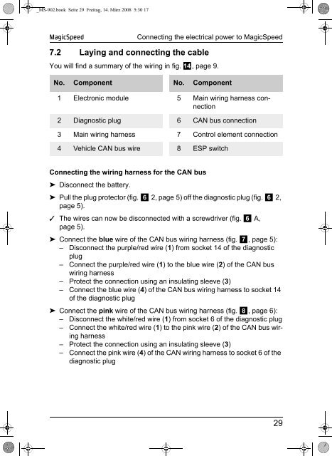
7.2 Laying and connecting the cable<br />
You will find a summary of the wiring in fig. d, page 9.<br />
No. Component No. Component<br />
1 Electronic module 5 Main wiring harness connection<br />
2 Diagnostic plug 6 CAN bus connection<br />
3 Main wiring harness 7 Control element connection<br />
4 Vehicle CAN bus wire 8 ESP switch<br />
Connecting the wiring harness for the CAN bus<br />
➤ Disconnect the battery.<br />
➤ Pull the plug protector (fig. 6 2, page 5) off the diagnostic plug (fig. 6 2,<br />
page 5).<br />
✓ The wires can now be disconnected with a screwdriver (fig. 6 A,<br />
page 5).<br />
➤ Connect the blue wire of the CAN bus wiring harness (fig. 7, page 5):<br />
– Disconnect the purple/red wire (1) from socket 14 of the diagnostic<br />
plug<br />
– Connect the purple/red wire (1) to the blue wire (2) of the CAN bus<br />
wiring harness<br />
– Protect the connection using an insulating sleeve (3)<br />
– Connect the blue wire (4) of the CAN bus wiring harness to socket 14<br />
of the diagnostic plug<br />
➤ Connect the pink wire of the CAN bus wiring harness (fig. 8, page 6):<br />
– Disconnect the white/red wire (1) from socket 6 of the diagnostic plug<br />
– Connect the white/red wire (1) to the pink wire (2) of the CAN bus wiring<br />
harness<br />
– Protect the connection using an insulating sleeve (3)<br />
– Connect the pink wire (4) of the CAN wiring harness to socket 6 of the<br />
diagnostic plug<br />
29