Drehgeber für Funktionale Sicherheit - Fritz Kübler GmbH Zähl- und ...
Drehgeber für Funktionale Sicherheit - Fritz Kübler GmbH Zähl- und ...
Drehgeber für Funktionale Sicherheit - Fritz Kübler GmbH Zähl- und ...
Sie wollen auch ein ePaper? Erhöhen Sie die Reichweite Ihrer Titel.
YUMPU macht aus Druck-PDFs automatisch weboptimierte ePaper, die Google liebt.
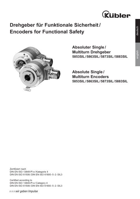
<strong>Drehgeber</strong> <strong>für</strong> <strong>Funktionale</strong> <strong>Sicherheit</strong>/<br />
Encoders for Functional Safety<br />
Zertifiziert nach<br />
DIN EN ISO 13849-Pl e / Kategorie 4<br />
DIN EN ISO 61508 / DIN EN ISO 61800-5-2-SIL3<br />
Certified according to<br />
DIN EN ISO 13849-Pl e / Category 4<br />
DIN EN ISO 61508 / DIN EN ISO 61800-5-2-SIL3<br />
Absoluter Single/<br />
Multiturn <strong>Drehgeber</strong><br />
5853SIL/5863SIL/5873SIL/5883SIL<br />
Absolute Single/<br />
Multiturn Encoders<br />
5853SIL/5863SIL/5873SIL/5883SIL<br />
english deutsch
© <strong>Fritz</strong> <strong>Kübler</strong> <strong>GmbH</strong><br />
Urheberrechtschutz<br />
Für diese Dokumentation besteht Urheberrechtschutz durch die Firma <strong>Fritz</strong> <strong>Kübler</strong> <strong>GmbH</strong>. Diese<br />
Dokumentation darf ohne vorherige schriftliche Zustimmung der Firma <strong>Fritz</strong> <strong>Kübler</strong> <strong>GmbH</strong> weder<br />
abgeändert, erweitert oder vervielfältigt noch an Dritte weitergegeben werden.<br />
Änderungsvorbehalt<br />
Technische Änderungen der in dem vorliegenden Dokument enthaltenen technischen Informationen,<br />
die aus dem stetigen Bestreben zur Verbesserung unserer Produkte resultieren, behalten wir uns<br />
jederzeit vor.<br />
Verzicht auf Garantie<br />
Die <strong>Fritz</strong> <strong>Kübler</strong> <strong>GmbH</strong> übernimmt in Bezug auf das gesamte Handbuch keine Garantie, weder stillschweigend<br />
noch ausdrücklich <strong>und</strong> haftet weder <strong>für</strong> direkte noch indirekte Schäden.<br />
Dokumenteninformation<br />
Ausgabestand 07.2010<br />
<strong>Fritz</strong> <strong>Kübler</strong> <strong>GmbH</strong> Schubertstr.47<br />
78054 VS-Schwenningen/Germany<br />
Tel. +49 (0) 7720-3903-0<br />
Fax +49 (0) 7720-21564<br />
E-Mail: info@kuebler.com<br />
Internet: www.kuebler.com<br />
2
Inhaltsangabe<br />
1. Funktion des <strong>Drehgeber</strong>s ................................................................................................4<br />
2. <strong>Sicherheit</strong>sfunktionen ......................................................................................................4<br />
3. <strong>Sicherheit</strong>skonzept ............................................................................................................5<br />
4. <strong>Sicherheit</strong>skennwerte ........................................................................................................6<br />
5. Datenübertragung................................................................................................................6<br />
Sinus- <strong>und</strong> Cosinus Signale ..........................................................................................................7<br />
SSI-Datenübertragung ..................................................................................................................8<br />
6. EMV Hinweise ........................................................................................................................8<br />
7. Montage des <strong>Drehgeber</strong>s ................................................................................................9<br />
Allgemeine Montagehinweise........................................................................................................9<br />
Montagehinweise <strong>für</strong> Geber mit Welle ........................................................................................10<br />
Montagehinweise <strong>für</strong> Geber mit Hohlwelle..................................................................................10<br />
<strong>Drehgeber</strong> mit Vollwelle <strong>und</strong> Fläche............................................................................................11<br />
<strong>Drehgeber</strong> mit Vollwelle <strong>und</strong> Passfeder ......................................................................................11<br />
<strong>Drehgeber</strong> mit Konuswelle <strong>und</strong> SIL-Statorkupplung ..................................................................12<br />
<strong>Drehgeber</strong> mit Hohlwelle, Klemmring, Drehmomentstütze <strong>und</strong> Drehmomentstift ......................12<br />
<strong>Drehgeber</strong> mit Hohlwelle, Klemmring <strong>und</strong> SIL-Statorkupplung ..................................................13<br />
8. Inbetriebnahme des <strong>Drehgeber</strong>s................................................................................13<br />
Anschließen der Anschlussdrähte ..............................................................................................13<br />
Betriebsbereitschaft beim Einschalten ........................................................................................13<br />
9. Checkliste <strong>für</strong> die Inbetriebnahme ............................................................................14<br />
3<br />
deutsch
2. <strong>Sicherheit</strong>sfunktionen<br />
4<br />
1. Funktion des <strong>Drehgeber</strong>s<br />
Die <strong>Drehgeber</strong>typen der 58x3SIL- Familie liefern<br />
ein Absolut- <strong>und</strong> ein Inkrementalsignal.<br />
Die Absolutposition wird in Form eines digitalen<br />
SSI- oder BiSS- Datenworts übertragen. Bei den<br />
Singleturn Varianten 5853SIL <strong>und</strong> 5873SIL<br />
beträgt die Auflösung je nach Variante zwischen<br />
10bit <strong>und</strong> 17bit. Die Multiturn-Varianten 5863SIL<br />
/ 5883SIL haben im Vergleich zu den Singleturn-<br />
Varianten 5853SIL / 5873SIL zusätzlich ein<br />
Getriebe zur Erfassung der absoluten Positionen<br />
größer 360°. Die Anzahl zur Erfassung der<br />
Umdrehungen beträgt 12bit.<br />
Die Inkrementalposition wird in Form eines analogen<br />
Sinus-Cosinus- Signals bereitgestellt. Die<br />
Auflösung beträgt pro Umdrehung 2048 Sinus-<br />
Cosinus Perioden.<br />
Die <strong>Drehgeber</strong> besitzen große, verblockte Lager,<br />
wodurch die <strong>Drehgeber</strong> sehr robust, genau <strong>und</strong><br />
langlebig sind.<br />
Der IP-Schutz ist je nach Dichtung des <strong>Drehgeber</strong><br />
IP65 oder IP67. Durch die optische Abtastung<br />
von Singleturn <strong>und</strong> Multiturn ist der <strong>Drehgeber</strong><br />
magnetisch unempfindlich.<br />
Nach DIN EN 61800-5-2 sind folgenden <strong>Sicherheit</strong>sfunktionen mit dem <strong>Drehgeber</strong> realisierbar:<br />
• SS1: Safe Stop 1 überwachtes Bremsen, STO nach Zeit oder Stillstand<br />
• SS2: Safe Stop 2 überwachtes Bremsen bis SOS<br />
• SOS: Safe Operating Stop sicherer Betriebshalt in Lageregelung<br />
• SLS: Safe Limited Speed sichere begrenzte Geschwindigkeit<br />
• SLI: Safe Limited Increment of Position sicher begrenztes Schrittmaß<br />
• SLP: Safe Limited Position sicher begrenzte Positionierung<br />
• SSR: Safe Speed Range sicherer Geschwindigkeitsbereich<br />
• SDI: Safe Direction sichere Richtung<br />
• SSM: Safe Speed Monitoring sichere Geschwindigkeitsüberwachung
3. <strong>Sicherheit</strong>skonzept<br />
!<br />
Sichere Inkrementalgeberfunktion<br />
Um mit dem <strong>Drehgeber</strong> eine sichere<br />
Inkrementalinformation zu erreichen,<br />
muss die Steuerung die Gültigkeit der<br />
analogen, um 90° zueinander versetzten<br />
Sinus-Cosinus Signale mit Hilfe<br />
der Funktion<br />
sin² (x) + cos² (x) = 1 überwachen.<br />
Gültigkeit<br />
sin2(x)+cos2(x)= Beim Einschalten / Abschalten der Anlage<br />
Vor dem Abschalten der Anlage wird<br />
der absolute Positionswert von der<br />
Steuerung gespeichert. Beim Wiedereinschalten<br />
vergleicht die Steuerung<br />
den abgespeicherten Wert mit dem,<br />
nach dem Einschalten, neu gemessenen<br />
absoluten Wert.<br />
! !<br />
Sind beide Werte identisch, so ist die<br />
Position sicher.<br />
Sind die Positionswerte nicht identisch,<br />
ist die Position nicht sicher, <strong>und</strong><br />
es muss die Position neu verifiziert<br />
werden.<br />
!<br />
Sichere Absolutgeberfunktion<br />
Um mit dem <strong>Drehgeber</strong> eine sichere<br />
Information über die absolute Position<br />
zu erhalten, zählt die Steuerung die<br />
Inkrementalimpulse <strong>und</strong> vergleicht<br />
das Ergebnis mit der ebenfalls vom<br />
<strong>Drehgeber</strong> bereitgestellten Absolutpositionen.<br />
Während des Betriebes der Anlage<br />
Durch den Vergleich der digitalen<br />
Positionsdaten mit den Sinus-Cosinus<br />
Signalen, welche von der Steuerung<br />
ständig mitgezählt <strong>und</strong> verglichen<br />
werden, wird die gemeldete Position<br />
verifiziert.<br />
Mechanische Fehler, wie z.B. ein<br />
Bruch der starren Drehmomentstütze<br />
mit Drehmomentstift oder das Abfallen<br />
des <strong>Drehgeber</strong>s von der Motorwelle,<br />
werden durch mechanische Überdimensionierung<br />
der Bauteile unserer<br />
Safety Geber ausgeschlossen.<br />
Der <strong>Drehgeber</strong> ist nur in Verbindung<br />
mit einer sicheren Steuerung, die die<br />
genannten Funktionen überwachen<br />
kann, sicher.<br />
5<br />
deutsch
4. <strong>Sicherheit</strong>skennwerte<br />
Gebrauchsdauer des <strong>Drehgeber</strong>s: 20 Jahre<br />
PFH Wert:<br />
je nach Versorgungsspannung des <strong>Drehgeber</strong>s<br />
5V DC Variante: 1,08 * 10 -8 1/h<br />
10-30V Variante: 1,09 * 10 -8 1/h<br />
5. Datenübertragung<br />
Sinus- <strong>und</strong> Cosinus Signale<br />
A - A = Sin; B – B = Cos<br />
Die analogen Signale müssen differentiell<br />
gemessen werden, das heißt A minus A ergibt<br />
Sinus, B minus B ergibt Cosinus.<br />
Die Signale A, A , B, B haben jeweils eine<br />
Amplitude von 0,5Vss bei einem Offset von<br />
+2,5V gegenüber 0V. Differentiell gemessen<br />
haben die Sinus- <strong>und</strong> Cosinus Signale eine<br />
Amplitude von 1Vss, bei einer Phasenlage von<br />
90°. Die Auflösung der inkrementellen Spur<br />
beträgt je 2048 Sinus-Cosinus Perioden.<br />
Die Gültigkeit der <strong>Sicherheit</strong>sfunktion muss mit<br />
der Funktion sin²(x) + cos²(x) = 1 überprüft werden.<br />
Der empfohlene Toleranzbereich <strong>für</strong> den<br />
<strong>Drehgeber</strong> liegt zwischen 0,5 <strong>und</strong> 1,5. Dieser<br />
Wert muss jedoch mit der gewünschten <strong>Sicherheit</strong>sfunktion<br />
verifiziert werden. Faktoren die hier<br />
mitbetrachtet werden müssen, sind Abtastfrequenz,<br />
die Eingangsbeschaltung <strong>und</strong> die rechnerische<br />
Auswertung der SinCos- Signale in der<br />
Steuerung. Aus diesem Gr<strong>und</strong> muss der Steuerungshersteller<br />
die Toleranzgrenzen der sin²(x) +<br />
cos²(x) Funktion erneut verifizieren.<br />
Die Gültigkeit der <strong>Sicherheit</strong>sfunktion kann pro<br />
Inkrement untersucht werden. Das heißt bei<br />
einer Auflösung von 2048 Sinus-Cosinus Perioden,<br />
kann die Gültigkeit von der Steuerung pro<br />
Umdrehung 2048-mal überprüft werden. Bei<br />
einer Toleranz der sin²(x) + cos²(x) Funktion von<br />
+/-0,5 beträgt der max. mögliche Fehlerweg 10%<br />
einer Signalperiode (36° el.).<br />
6<br />
Offset: 2,5V +/- 50mV<br />
Offset- Differenz A zu B max. 25mV<br />
Amplitude: 1Vss +/-100mV<br />
Amplituden- Differenz A zu B max.<br />
40mV<br />
Abschlusswiderstand:<br />
120 Ohm (A – A<br />
; B – B )
<strong>Drehgeber</strong> Empfohlene Eingangsschaltung<br />
R a = 10 �<br />
C 1 = 150 pF<br />
C 2 = 10 pF<br />
R 1 = 10 k�<br />
R 2 = 33 k�<br />
U 0 = 2,5 V � 0,5 V<br />
Signale gegen 0V gemessen<br />
Signale differentiell gemessen<br />
U/<br />
0,5<br />
0<br />
-0,5<br />
Z = 120 �<br />
U 1 = U0<br />
Drehrichtung: cw<br />
OPV: z.B. MC33074<br />
B<br />
A<br />
A<br />
B<br />
Cos<br />
Sin<br />
7<br />
deutsch
SSI - Datenübertragung<br />
Über die SSI-Schnittstelle wird die absolute<br />
Position als digitales Datenwort an die Steuerung<br />
übertragen.<br />
Die serielle, differentielle Übertragung<br />
besteht aus zwei Taktleitungen <strong>und</strong> zwei<br />
Datenleitungen. Über die Taktleitung schickt<br />
die Steuerung Takte, über die Datenleitung<br />
liefert der <strong>Drehgeber</strong> die Positionsdaten. Am<br />
Eingang der Steuerung muss ein Abschlusswiderstand<br />
von 120 Ohm an die Datenleitung<br />
angeschlossen werden.<br />
Im Ruhezustand liegen die Takt- <strong>und</strong> Datenleitungen<br />
auf High-Pegel. Mit der ersten fallenden<br />
Taktflanke werden die aktuellen Encoder-Daten<br />
<strong>für</strong> die Ausgabe im Puffer gespeichert. Mit den<br />
danach steigenden Taktflanken werden die Daten<br />
bitweise, beginnend mit MSB (Most Significant<br />
Bit), übertragen. Das Übertragen eines vollständigen<br />
Datenwortes erfordert n+1 steigende Taktflanken<br />
(n = Auflösung in Bit), z.B. 14 Taktsignale<br />
<strong>für</strong> eine vollständige Auslesung eines 13 Bit<br />
Gebers. Nach der letzten positiven Taktflanke<br />
verbleibt die Datenleitung <strong>für</strong> die Dauer der<br />
Monoflopzeit t3 auf Low, bis der Geber wieder <strong>für</strong><br />
ein neues Datenwort bereit ist. Die Taktleitung<br />
muss mindestens ebenso lange auf<br />
6. EMV Hinweise<br />
• Verwenden Sie nur geschirmte <strong>und</strong> paarig verseilte<br />
Leitungen <strong>für</strong> das <strong>Drehgeber</strong>kabel.<br />
• Legen Sie den Schirm großflächig <strong>und</strong> beidseitig<br />
auf Masse. Achten Sie auf eine einwandfreie<br />
Befestigung der Leitungsschirme.<br />
• Achten Sie bei der Verdrahtung ihrer Anlage<br />
auf eine ordnungsgemäße Leitungsführung.<br />
Trennen Sie die Verkabelung in Leitungsgruppen<br />
wie Motor- / Stromversorgungsleitungen<br />
<strong>und</strong> Signal- / Datenleitungen. Führen Sie Signal-<br />
<strong>und</strong> Datenleitungen möglichst eng an<br />
Masseflächen (Tragholmen, Metallschienen,<br />
Schrankblechen) <strong>und</strong> nicht parallel zu Motor<br />
<strong>und</strong> Stromversorgungsleitung.<br />
• Verbinden Sie alle Betriebsmittel impedanzarm<br />
mit dem Erdungs- / Schutzleitersystem.<br />
8<br />
<strong>Drehgeber</strong> Eingang Steuerung<br />
RS485 Transceiver<br />
+5V +5V<br />
Daten +<br />
+5V<br />
10k<br />
120 Z<br />
10k<br />
Takt +<br />
Daten -<br />
High verbleiben, <strong>und</strong> kann danach wieder mit<br />
einer fallenden Flanke eine neue Auslesesequenz<br />
des Gebers beginnen.<br />
BISS-Interface:<br />
Details zum BISS-Interface finden Sie auf unserer<br />
Website unter:<br />
www.kuebler.com/service/Biss.pdf<br />
Takt -<br />
Z<br />
Z = 120 Ohm<br />
RS485 Transceive<br />
z.B. MAX 490<br />
t1 = T / 2<br />
t2 < 1 / (4 x fmax)<br />
t3 = Monoflopzeit (s. unten)<br />
n = Auflösung in Bit<br />
1/ fmax =< T =< 1 / fmin<br />
fmin = min. SSI-Taktrate<br />
(s. Datenblatt)<br />
fmax = max. SSI-Taktrate<br />
(s. Datenblatt)
!<br />
7. Montage des <strong>Drehgeber</strong>s<br />
Allgemeine Montagehinweise<br />
Der <strong>Drehgeber</strong> darf weder teilweise noch ganz<br />
zerlegt oder modifiziert werden.<br />
Die Welle nicht nachträglich bearbeiten (schleifen,<br />
sägen, bohren, usw.). Die Genauigkeit des<br />
Gebers <strong>und</strong> die Zuverlässigkeit von Lager <strong>und</strong><br />
Dichtung nehmen sonst Schaden. Wir sind<br />
gerne bereit, auf Ihre Wünsche<br />
einzugehen.<br />
Das Gerät niemals mit dem Hammer ausrichten.<br />
Schlagbelastungen unbedingt vermeiden. –<br />
<strong>Drehgeber</strong>welle nicht über die im Datenblatt<br />
angegebenen Werte belasten (weder axial noch<br />
radial).<br />
<strong>Drehgeber</strong> <strong>und</strong> Antriebsgerät nicht an Wellen<br />
<strong>und</strong> Flanschen starr miteinander verbinden.<br />
Benutzen Sie gr<strong>und</strong>sätzlich eine Kupplung (zwischen<br />
Antriebswelle <strong>und</strong> Geberwelle, bzw. zwischen<br />
Hohlwellen-Geber-Flansch <strong>und</strong> Antriebsflansch).<br />
Kupplungen sind so auszulegen, dass sie den<br />
Anforderungen der DIN EN ISO 13849 entsprechen,<br />
bzw. dass ein Bruch der Verbindung ausgeschlossen<br />
werden kann.<br />
9<br />
deutsch
Montagehinweise <strong>für</strong> Geber mit Welle<br />
• Wellen auf Versatz überprüfen.<br />
• Toleranz ausgleichendes Element während der Montage vor zu starker Biegung sowie Beschädigung<br />
schützen.<br />
• Kupplung auf den Wellen ausrichten, ohne Vorspannung verschrauben.<br />
Die Verbindung zwischen Geber <strong>und</strong> Antriebswelle ist so auszulegen, dass ein Bruch der Verbindung<br />
ausgeschlossen werden kann.<br />
Montagehinweise <strong>für</strong> Geber mit Hohlwelle<br />
Geber mit Kupplung auf Welle montieren<br />
Folgende Reihenfolge muss bei der Montage eingehalten werden:<br />
1. Geber mit Kupplung auf Welle montieren<br />
2. Kupplung mit Antriebsflansch verschrauben.<br />
3. Klemmnabe mit Solldrehmoment anziehen<br />
10
<strong>Drehgeber</strong> mit Vollwelle <strong>und</strong> Fläche, Flansch Typ 1 (siehe Datenblatt 58x3SIL)<br />
Die Befestigung des Vollwellendrehgebers erfolgt über die im Flansch vorgesehenen Gewindebohrungen<br />
mit mindestens drei Schrauben M3 der Festigkeitsklasse 8.8, die mit einem empfohlenem<br />
Drehmoment von 1Nm (angenommener Reibwert 0,14) angezogen <strong>und</strong> gegen Lösen gesichert werden<br />
müssen. Die Anbindung der Welle muss über ein Toleranz ausgleichendes Element mit dem<br />
Antrieb verb<strong>und</strong>en werden <strong>und</strong> gegen Lösen gesichert werden. Bei der Anbindung der Vollwelle<br />
muss der Betreiber oder der Installationsbetrieb, der den <strong>Drehgeber</strong> befestigt, sicherstellen, dass die<br />
Befestigungsmethode den gültigen <strong>Sicherheit</strong>sanforderungen entspricht.<br />
1<br />
2<br />
58<br />
53<br />
36<br />
10 f7<br />
20<br />
3<br />
10<br />
3<br />
a<br />
13,25<br />
3xM3, 6 tief 5853SIL 5863SIL<br />
Maß<br />
Singleturn Multiturn<br />
3xM4, 8 tief<br />
a 38 49,5<br />
58,5<br />
<strong>Drehgeber</strong> mit Vollwelle <strong>und</strong> Passfeder, Flansch Typ 1 (siehe Datenblatt 58x3SIL)<br />
Die Befestigung des Vollwellendrehgebers mit Passfeder erfolgt über die im Flansch vorgesehenen<br />
Gewindebohrungen mit mindestens drei M3 Schrauben der Festigkeitsklasse 8.8, die mit einem empfohlenem<br />
Drehmoment von 1 Nm (angenommener Reibwert 0,14) angezogen <strong>und</strong> gegen Lösen gesichert<br />
werden müssen. Die Anbindung der Welle muss über ein Toleranz ausgleichendes Element mit<br />
dem Antrieb verb<strong>und</strong>en <strong>und</strong> gegen Lösen gesichert werden. Bei der Anbindung der Vollwelle mit<br />
Passfeder muss der Betreiber oder der Installationsbetrieb, der den <strong>Drehgeber</strong> befestigt, sicherstellen,<br />
dass die Befestigungsmethode den gültigen <strong>Sicherheit</strong>sanforderungen entspricht.<br />
58<br />
53 -0,1<br />
36 f8<br />
H7<br />
10<br />
20<br />
3<br />
10<br />
1 3xM3, 6 tief<br />
2 3xM4, 8 tief<br />
3 Passfeder DIN 6885 - A - 3x3x6<br />
Optional: Passfeder DIN 6885 - A - 4x4x8<br />
6<br />
3<br />
a<br />
13,25<br />
58,5<br />
Maß<br />
120°<br />
3x120°<br />
5853SIL<br />
Singleturn<br />
5863SIL<br />
Multiturn<br />
a 38 49,5<br />
20°<br />
20°<br />
1<br />
1<br />
2<br />
48 ±0,1<br />
2<br />
11<br />
deutsch
<strong>Drehgeber</strong> mit Konuswelle <strong>und</strong> SIL-Statorkupplung, Flansch Typ B (siehe Datenblatt 58x3SIL)<br />
Die Befestigungsschraube der Konuswelle muss mit 3Nm angezogen werden. Für die Befestigung<br />
der Statorkupplung müssen vier M3 Schrauben der Festigkeitsklasse 8.8 verwendet werden, die mit<br />
einem empfohlenem Drehmoment von 1 Nm (angenommener Reibwert 0,14) angezogen <strong>und</strong> gegen<br />
Lösen gesichert werden müssen. Der Betreiber oder der Installationsbetrieb, der den <strong>Drehgeber</strong><br />
befestigt, muss sicherstellen, dass die Befestigungsmethode den gültigen <strong>Sicherheit</strong>sanforderungen<br />
entspricht.<br />
max. zulässige Toleranzen der Wellenverbindung:<br />
- Axialversatz: 0,50 mm (+/-0,25 mm)<br />
- Radialversatz: +/- 0,20 10:1 mm<br />
- Winkelversatz: 1°<br />
58<br />
52<br />
50<br />
10<br />
8,8<br />
M5<br />
10:1<br />
8,9<br />
21,7<br />
31,5<br />
a<br />
b<br />
c<br />
d<br />
1 <strong>für</strong> (4x) M3 Schraube<br />
13,25<br />
2 SW 4, empfohlenes Anzugsdrehmoment 3Nm<br />
(angenommener Reibwert 0,14)<br />
58<br />
50<br />
31<br />
ca.<br />
Maß<br />
a<br />
b<br />
c<br />
d<br />
13,25<br />
5873SIL<br />
Singleturn<br />
58,5<br />
5883SIL<br />
Multiturn<br />
a 56 67,5<br />
b 47 58,5<br />
c 41 52,5<br />
d 35 46,5<br />
25<br />
6 G6<br />
N510283<br />
Maß<br />
a<br />
7<br />
M4<br />
8<br />
58,5<br />
5873SIL<br />
Singleturn<br />
6,2<br />
2<br />
10<br />
25<br />
Maß<br />
5883SIL<br />
Multiturn<br />
22<br />
5873SIL<br />
Singleturn<br />
25°<br />
5883SIL<br />
Multiturn<br />
a 59 67,5<br />
b 48 56,5<br />
c 44 52,5<br />
d 38 46,5<br />
25<br />
34<br />
150<br />
143,5<br />
127,5<br />
110<br />
25<br />
20<br />
25<br />
92,5<br />
25<br />
75<br />
6<br />
10<br />
57,5<br />
22,8 242698<br />
Drehmomentstift mit Vierkanthülse<br />
mit M4 Gewinde, 10 tief<br />
68<br />
63 ±0,1<br />
SW 8<br />
M<br />
1<br />
H7<br />
14<br />
N510286<br />
<strong>Drehgeber</strong> mit Hohlwelle, Klemmring, Drehmomentstütze <strong>und</strong> Drehmomentstift, Flansch Typ A<br />
(siehe Datenblatt 58x3SIL)<br />
Die Befestigungsschraube des Klemmringes muss mit einem empfohlenem 2,5 Nm (angenommener<br />
Reibwert 0,14) angezogen werden. Der Drehmomentstift muss auf einem M4 Gewindestift der<br />
Festigkeitsklasse 8.8 aufgeschraubt <strong>und</strong> mit einem empfohlenem Drehmoment von 3 Nm (angenommener<br />
Reibwert 0,14) angezogen werden. Die Schraubverbindung muss gegen Lösen gesichert sein.<br />
Der Drehmomentstift muss nach den gültigen Maschinenrichtlinien montiert werden, bei denen der<br />
Betreiber oder der Installationsbetrieb, der den <strong>Drehgeber</strong> befestigt, sicherstellen muss, dass das<br />
Befestigungsgewinde den gültigen <strong>Sicherheit</strong>sanforderungen entspricht.<br />
12<br />
Auflagefläche Drehmomentstütze –<br />
Drehmomentstifte fetten
<strong>Drehgeber</strong> mit Hohlwelle, Klemmring <strong>und</strong> SIL-Statorkupplung , Flansch Typ B (siehe Datenblatt<br />
58x3SIL)<br />
Die Befestigungsschraube des Klemmringes muss mit empfohlenen Drehmoment von 2,5 Nm<br />
(angenommener Reibwert 0,14) angezogen werden. Für die Befestigung der Statorkupplung müssen<br />
vier M3 Schrauben der Festigkeitsklasse 8.8 verwendet werden, die mit einem empfohlenen Drehmoment<br />
von einem 1 Nm (angenommener Reibwert 0,14) angezogen <strong>und</strong> gegen Lösen gesichert werden.<br />
Der Betreiber oder der Installationsbetrieb, der den <strong>Drehgeber</strong> befestigt, muss sicherstellen,<br />
dass die Befestigungsmethode den gültigen <strong>Sicherheit</strong>sanforderungen entspricht.<br />
max. zulässige Toleranzen der Wellenverbindung:<br />
- Axialversatz: 0,50 mm (+/-0,25 mm)<br />
- Radialversatz: +/- 0,20 mm<br />
- Winkelversatz: 1°<br />
58<br />
53<br />
50<br />
ca. 31<br />
1<br />
2<br />
2<br />
a<br />
b<br />
c<br />
13,25<br />
3xM3, 6 tief 5853SIL<br />
Maß<br />
Singleturn<br />
3xM4, 8 tief<br />
a 38 49,5<br />
8. Inbetriebnahme des <strong>Drehgeber</strong>s<br />
58,5<br />
Anschließen der Anschlussdrähte<br />
22<br />
25°<br />
5863SIL<br />
Multiturn<br />
68<br />
63 ±0,1<br />
H7<br />
14<br />
1<br />
N510286<br />
Beim Anschließen der Anschlussdrähte ist die ordnungsgemäße Funktion zu prüfen.<br />
o Zu überprüfen ist das ordnungsgemäße Anliegen der Versorgungsspannung. Ist die Versorgungsspannung<br />
vertauscht, so arbeitet der <strong>Drehgeber</strong> nicht, es werden keine Signale ausgegeben.<br />
o Zu überprüfen ist die Kommunikation der SSI- / BiSS-Schnittstelle. Bei einer Fehlverdrahtung ist<br />
keine Kommunikation möglich. Der Abschlusswiderstand der Datenleitung muss mit 120 Ohm<br />
abgeschlossen werden.<br />
o Zu überprüfen ist das ordnungsgemäße Anliegen der Sinus-Cosinus Signale, die Amplitudenhöhe,<br />
Polung <strong>und</strong> die Phasenlage. Ist ein Fehler im Sinus-Cosinus Pfad vorhanden, so ist die Funktion<br />
sin 2 (x) + cos 2 (x) = 1 nicht erfüllt oder die Drehrichtung ist falsch, z.B. durch das Vertauschen<br />
von Sin <strong>und</strong> Cos (falsche Phasenlage).<br />
Betriebsbereitschaft beim Einschalten<br />
Nach dem Einschalten der Versorgungsspannung stehen die Sinus-Cosinus Signale sofort an, es<br />
muss jedoch mindestens 150ms gewartet werden bis der <strong>Drehgeber</strong> betriebsbereit ist, d.h. bis die<br />
Schnittstellen kommunikationsbereit sind. Erst ab dieser Zeit kommuniziert der <strong>Drehgeber</strong> über die<br />
SSI- oder BiSS-Schnittstelle nach außen.<br />
13<br />
deutsch
9. Checkliste <strong>für</strong> die Inbetriebnahme<br />
✓ ✘<br />
Montage (Infos siehe Montagehinweise)<br />
14<br />
Der <strong>Drehgeber</strong> darf nur mit den von der Firma <strong>Fritz</strong> <strong>Kübler</strong> <strong>GmbH</strong> montierten Befestigungselementen<br />
installiert werden.<br />
Die Wellenbelastung des <strong>Drehgeber</strong>s, durch den Anbau / Montage, ist so gering wie möglich<br />
zuhalten. Dabei müssen die vorgegebenen Einbaumaße, des <strong>Drehgeber</strong>s, zwingend eingehalten<br />
werden. Es ist auch darauf zu achten, dass die toleranzausgleichenden Elemente ohne<br />
Vorspannung montiert werden.<br />
Bei der Montage ist auf einen geringen Axial- <strong>und</strong> Radialversatz zu achten, damit die angegebenen<br />
maximalen Werte nicht überschritten werden.<br />
Für die Wellentoleranz der Antriebswelle, auf die der <strong>Drehgeber</strong> gesteckt wird, wird g6 (bei<br />
Vollwellengeber) / G6 (bei Hohlwellengeber) vorgeschrieben.<br />
Anschluss Elektronik (Belegung siehe Datenblatt)<br />
Steuerung<br />
Pegel <strong>und</strong> Polarität der Versorgungsspannung geprüft<br />
SSI-, BiSS-Kommunikation funktionsfähig<br />
Abschlusswiderstand 120 Ohm (A – A<br />
; B – B )<br />
Drehrichtung <strong>und</strong> <strong>Zähl</strong>richtung stimmen überein<br />
Sin 2 (x) + Cos 2 (x) = 1 Überwachung aktiviert<br />
Für eine sichere Absolutposition wird der Inkrementalwert mitgezählt <strong>und</strong> mit dem Absolutwert<br />
des <strong>Drehgeber</strong>s verglichen<br />
Vor dem Abschalten der Anlage wird der absolute Positionswert von der Steuerung gespeichert.<br />
Beim Wiedereinschalten vergleicht die Steuerung den abgespeicherten Wert mit dem,<br />
nach dem Einschalten, neu gemessenen absoluten Wert.
© <strong>Fritz</strong> <strong>Kübler</strong> <strong>GmbH</strong><br />
Copyright Protection<br />
The contents of this documentation are protected by copyright © <strong>Fritz</strong> <strong>Kübler</strong> <strong>GmbH</strong>. The contents of<br />
this documentation may not be altered, expanded, reproduced or circulated to third parties, without<br />
the prior written agreement of <strong>Fritz</strong> <strong>Kübler</strong> <strong>GmbH</strong>.<br />
Liability to modification without notice<br />
As a result of ongoing efforts to improve our products, we reserve the right to make changes at any<br />
time to technical information contained in the document to hand.<br />
Warranty Disclaimer<br />
<strong>Fritz</strong> <strong>Kübler</strong> <strong>GmbH</strong> provides no guarantee, neither tacit nor express, in respect of the whole manual<br />
(whether this applies to the original German text or to the English translation) and assumes no liability<br />
for any damage, either direct or indirect, however caused.<br />
Document information<br />
Revised 07.2010<br />
<strong>Fritz</strong> <strong>Kübler</strong> <strong>GmbH</strong> Schubertstr.47<br />
78054 VS-Schwenningen/Germany<br />
Tel. +49 (0) 7720-3903-0<br />
Fax +49 (0) 7720-21564<br />
E-Mail: info@kuebler.com<br />
Internet: www.kuebler.com<br />
1<br />
english
Table of Contents<br />
1. Function of the encoder ..................................................................................................3<br />
2. Safety functions ..................................................................................................................3<br />
3. Safety concept ......................................................................................................................4<br />
4. Safety characteristics ........................................................................................................5<br />
5. Data transmission ..............................................................................................................5<br />
Sine and Cosine Signals ....................................................................................................................6<br />
SSI Data Transmission ......................................................................................................................7<br />
6. EMC Information ..................................................................................................................7<br />
7. Mounting the encoder ......................................................................................................8<br />
General Mounting advice ....................................................................................................................8<br />
Mounting advice for encoders with shaft ............................................................................................9<br />
Mounting advice for encoders with hollow shaft..................................................................................9<br />
Encoder with solid shaft and flat........................................................................................................10<br />
Encoder with solid shaft and feather key ..........................................................................................10<br />
Encoder with tapered shaft and SIL stator coupling..........................................................................11<br />
Encoder with hollow shaft, clamping ring, torque stop and torque pin..............................................11<br />
Encoder with hollow shaft, clamping ring and SIL stator coupling ....................................................12<br />
8. Initial Start- Up of the encoder....................................................................................12<br />
Hooking up the connection leads ......................................................................................................12<br />
Availability after start-up ....................................................................................................................12<br />
9. Checklist for start-up ......................................................................................................13<br />
2
2. Safety Funcions<br />
1. Function of the encoder<br />
The encoder types of the 58x3SIL family supply<br />
an absolute and an incremental signal.<br />
The absolute position is transmitted in the form<br />
of a digital SSI or BiSS data word. With the singleturn<br />
variants 5853SIL and 5873SIL, the resolution<br />
is between 10 bits and 17 bits, depending<br />
on the variant. In contrast to the singleturn variants<br />
5853SIL / 5873SIL, the multiturn variants<br />
5863SIL / 5883SIL have in addition a gear for<br />
detecting positions greater than 360°. The number<br />
for detecting the revolutions amounts to 12<br />
bits.<br />
The incremental position is provided by an analogue<br />
sine/cosine signal. The resolution per revolution<br />
is 2048 sine/cosine periods.<br />
The encoders are equipped with large, interlocked<br />
bearings, ensuring that the encoders are<br />
very rugged, accurate with a long service life.<br />
The IP protection rating of the encoders is either<br />
IP65 or IP67, depending on the shaft seal fitted.<br />
As a result of the optical scanning of the singleturn<br />
and the multiturn, the encoders remain<br />
insensitive to magnetic fields.<br />
According to DIN EN 61800-5-2 the following safety functions can be implemented with the encoder:<br />
• SS1: Safe Stop 1<br />
• SS2: Safe Stop 2<br />
• SOS: Safe Operating Stop<br />
• SLS: Safe Limited Speed<br />
• SLI: Safe Limited Increment of Position<br />
• SLP: Safe Limited Position<br />
• SSR: Safe Speed Range<br />
• SDI: Safe Direction<br />
• SSM: Safe Speed Monitoring<br />
3<br />
english
3. Safety Concept<br />
When switching the plant on and off<br />
4<br />
!<br />
Incremental Encoder Funcion<br />
In order to achieve safe incremental<br />
information with the encoder, the controller<br />
must monitor the validity of the<br />
analogue, 90° phase-shifted<br />
sine/cosine signals with the help of<br />
the function<br />
sin²+cos² = 1.<br />
Prior to the plant being shut down the<br />
absolute position value is saved by<br />
the controller. When the plant is<br />
switched back on, the controller compares<br />
the saved value with the newly<br />
measured absolute value that has<br />
been made after power on.<br />
! !<br />
If both these values are identical, then<br />
the position is safe.<br />
If the position values are not identical,<br />
then the position is not safe and the<br />
position must be verified again.<br />
!<br />
Safe Absolute Encoder Function<br />
In order to obtain safe information<br />
with the encoder regarding the<br />
absolute position, the controller<br />
counts the incremental pulses and<br />
compares the result with the absolute<br />
positions also provided by the<br />
encoder.<br />
During plant operation<br />
The indicated position is verified by a<br />
comparison of the digital position data<br />
with the sine/cosine signals that are<br />
also constantly being counted and<br />
compared by the controller<br />
The risk of mechanical faults (as<br />
might occur, for example, if the rigid<br />
torque stop with torque pin were to<br />
break or the encoder to fall off the<br />
motor shaft) is eliminated as a result<br />
of the mechanical over-dimensioning<br />
of the components of our safety<br />
encoders.<br />
The encoder is safe only when used<br />
in conjunction with a safe controller<br />
that can monitor the functions mentioned.
4. Safety Characteristics<br />
Service life of the encoder: 20 years<br />
PFH value:<br />
dependent on the supply voltage of the encoder<br />
5V DC versions: 1.08 * 10 -8 1/h<br />
10-30V versions: 1.09 * 10 -8 1/h<br />
5. Data Transmission<br />
Sine and Cosine Signals<br />
A - A = Sin; B – B = Cos<br />
The analogue signals must be measured differentially,<br />
i.e. A minus A gives the sine, B minus<br />
B gives the cosine. The signals A, A , B, B<br />
each have an amplitude of 0.5Vss with an offset<br />
of +2.5V to 0V. Measured differentially, the sine<br />
and cosine signals have an amplitude of 1Vss,<br />
with a phase-shift of 90°.<br />
The resolution of the incremental track 2048<br />
sine/cosine periods depending on the variant.<br />
The validity of the safety function must be<br />
checked with the function sin²(x) + cos²(x) = 1.<br />
The recommended tolerance range for the<br />
encoder lies between 0.5 and 1.5. However this<br />
value must be verified with the desired safety<br />
function. Factors which must also be considered<br />
here include the scanning frequency, the input<br />
circuitry and the calculated evaluation of the Sin-<br />
Cos signals in the controller. For this reason the<br />
manufacturer of the controller must once again<br />
verify the tolerance limits of the sin² (x) + cos²<br />
(x) function.<br />
The validity of the safety function can be scrutinised<br />
per increment. This means that for a resolution<br />
of 2048 sine/cosine periods, the validity of<br />
the controller can be checked 2048 times per<br />
revolution. With a tolerance of the sin²(x) +<br />
cos²(x) function of +/-0.5, the max. possible error<br />
path is 10% of one signal period (36° el.).<br />
Offset: 2.5V +/- 50mV Offset difference A-B<br />
max. 25mV<br />
Amplitude: 1V +/-100mV<br />
Amplitude difference A-B max.<br />
40mV<br />
Terminating resistor: 120 Ohm<br />
(A – A<br />
; B – B )<br />
Due to tolerances, the deviation in the calculation<br />
of sin² + cos² can be between 0.7<br />
5<br />
english
Encoder Recommended input circuit<br />
R a = 10 �<br />
C 1 = 150 pF<br />
C 2 = 10 pF<br />
R 1 = 10 k�<br />
R 2 = 33 k�<br />
U 0 = 2,5 V � 0,5 V<br />
Signals measured against 0V<br />
Signals measured differentially<br />
6<br />
U/<br />
0,5<br />
0<br />
Z = 120 �<br />
U 1 = U0<br />
rotation: cw<br />
OPV: e.g. MC33074<br />
B<br />
A<br />
A<br />
B<br />
Cos<br />
Sin
SSI - Data Transmission<br />
The absolute position is transmitted via the SSI<br />
interface to the controller as a digital data word.<br />
The serial, differential transmission consists of<br />
two clock lines and two data lines. The controller<br />
sends clock pulses via the clock line and the<br />
encoder supplies the position data via the data<br />
line. A terminating resistor of 120 Ohm must be<br />
connected to the data line at the controller input.<br />
In the rest state, the clock and data lines are at a<br />
high level. With the first falling clock-pulse edge,<br />
the current encoder data are stored in the buffer<br />
ready to be sent. With the next rising clock-pulse<br />
edges the data are transmitted bit by bit, starting<br />
with the MSB (Most Significant Bit). The transfer<br />
of a complete data word requires n+1 rising<br />
clock-pulse edges (n = resolution in Bit), e.g. 14<br />
clock signals for a complete readout of a 13 Bit<br />
encoder. After the last positive clock-pulse edge<br />
the data line will remain at a low level for the<br />
period of the monoflop time t3 until the encoder<br />
is again ready for a new data word. The clock<br />
line must stay High for at least the same amount<br />
of time, and can then again begin a new read-out<br />
sequence of the encoder with the next falling<br />
edge.<br />
6. EMC Information<br />
• Use only shielded twisted-paired conductors as<br />
encoder cables.<br />
• Connect the shield at both ends to the gro<strong>und</strong><br />
on a large contact area. Make sure that the<br />
cable shields are well fastened.<br />
• When wiring your installation, take care to<br />
route the cables properly. Separate the wiring<br />
in cable groups such as motor / power supply<br />
cables and signal / data cables. Route the signal<br />
and data cables as close as possible to<br />
gro<strong>und</strong>ed surfaces (supporting beams, metal<br />
rails, cabinet sides) and not parallel to motor<br />
and power supply cables.<br />
• Connect all equipment with low impedance to<br />
the gro<strong>und</strong>/ protective conductor system.<br />
Encoder Control input<br />
RS485 Transceiver<br />
+5V +5V<br />
Data +<br />
+5V<br />
10k<br />
120 Z<br />
10k<br />
Clock+<br />
Data -<br />
Clock -<br />
t1 = T / 2<br />
t2 < 1 / (4 x fmax)<br />
t3 = Monoflop time (see below)<br />
n = Resolution in Bit<br />
1/ fmax =< T =< 1 / fmin<br />
fmin = min. SSI clock rate<br />
(see data sheet)<br />
fmax = max. SSI clock rate<br />
(see data sheet)<br />
BISS Interface:<br />
Details about the BISS Interface can be fo<strong>und</strong><br />
on our website at:<br />
www.kuebler.com/service/Biss.pdf<br />
Z<br />
Z = 120 Ohm<br />
RS485 Transceiver<br />
e.g. MAX 490<br />
z.B. MAX 490<br />
7<br />
english
8<br />
!<br />
7. Mounting the encoder<br />
General mounting advice<br />
The encoder must not be disassembled or modified,<br />
either in total or in part.<br />
No subsequent machining should be carried out<br />
on the shaft (grinding, sawing, drilling, etc.). This<br />
could impair the accuracy of the encoder and<br />
damage the bearings and shaft seals. We would<br />
be happy to accommodate your wishes.<br />
Never try to align the encoder using a hammer<br />
and never subject the encoder to impact shocks.<br />
Do not subject the encoder shaft to loads (axial<br />
or radial) that are higher than the values given in<br />
the data sheet.<br />
Do not rigidly connect the shafts and flanges of<br />
the encoder and drive device. Always use a coupling<br />
(between the drive shaft and the encoder<br />
shaft, or between flange of the hollow shaft<br />
encoder and the drive flange).<br />
Couplings are to be designed and dimensioned,<br />
so that they meet the requirements of DIN EN<br />
ISO 13849 or so that any possible breakage of<br />
the connection can be ruled out.
Mounting advice for encoders with shaft<br />
• Check the shafts for offset.<br />
• Protect the tolerance of the compensating element during mounting from too great a degree of<br />
bending and also from damage.<br />
• Align the coupling to the shafts, and screw together without pre-loading.<br />
The connection between encoder and drive shaft should be configured in such a way that it is impossible<br />
for the connection to break.<br />
Mounting advice for encoders with hollow shaft<br />
Mounting an encoder with a coupling on a shaft<br />
The following sequence must be adhered to when mounting the encoder:<br />
1. Mount the encoder with the coupling onto the shaft<br />
2. Screw the coupling onto the drive flange<br />
3. Tighten the clamping hub with the correct amount of torque<br />
9<br />
english
Encoder with solid shaft and flat, flange type 1 (see data sheet 58x3SIL)<br />
The fixing of the solid shaft encoder is carried out using the threaded holes provided in the flange<br />
and at least three M3 screws, property class 8.8; these are to be tightened with a recommended<br />
torque of 1Nm (assumed coefficient of friction 0.14) and secured against loosening. The connection<br />
of the shaft to the drive must be effected using a tolerance compensating element and secured<br />
against loosening. When connecting the solid shaft, the operator, operating company or installation<br />
company, which is installing the encoder, must ensure that the fixing method complies with the safety<br />
requirements in force.<br />
1<br />
2<br />
Encoder with solid shaft and feather key, flange type 1 (see data sheet 58x3SIL)<br />
The fixing of the solid shaft encoder with feather key is carried out using the threaded holes provided<br />
in the flange and at least three M3 screws, property class 8.8; these are to be tightened with a recommended<br />
torque of 1Nm (assumed coefficient of friction 0.14) and secured against loosening. The<br />
connection of the shaft to the drive must be effected using a tolerance compensating element and<br />
secured against loosening. When connecting the solid shaft with feather key, the operator, operating<br />
company or installation company, which is installing the encoder, must ensure that the fixing method<br />
complies with the safety requirements in force.<br />
10<br />
58<br />
53<br />
36<br />
10 f7<br />
20<br />
3<br />
10<br />
3<br />
a<br />
13,25<br />
5853SIL 5863SIL<br />
3xM3, 6 tief deep<br />
Dimension Maß 5853SIL 5863SIL<br />
Maß Singleturn Multiturn<br />
Singleturn Multiturn<br />
3xM4, 8 tief deep<br />
aa 38 49,5 49,5<br />
58<br />
53 -0,1<br />
36 f8<br />
H7<br />
10<br />
1 3xM3, 6 tief deep<br />
2 3xM4, 8 tief deep<br />
3 feather Passfeder key DIN 6885 - – A - – 3x3x6<br />
Optional: Passfeder Optional: feather DIN 6885 key DIN - A - 6885 4x4x8–<br />
A – 4x4x8<br />
20<br />
3<br />
10<br />
6<br />
3<br />
a<br />
13,25<br />
58,5<br />
58,5<br />
Dimension Maß<br />
120°<br />
3x120°<br />
5853SIL<br />
Singleturn<br />
20°<br />
20°<br />
5863SIL<br />
Multiturn<br />
a 38 49,5<br />
1<br />
1<br />
2<br />
48 ±0,1<br />
2
Encoder with tapered shaft and SIL stator coupling, flange type B (see data sheet 58x3SIL)<br />
The fixing screw of the tapered shaft must be tightened with a recommended torque of 3Nm. For fixing<br />
the stator coupling four M3 screws, property class 8.8, must be used, tightened with a recommended<br />
torque of 1Nm (assumed coefficient of friction 0.14) and secured against loosening. The<br />
operator, operating company or installation company, which is installing the encoder, must ensure<br />
that the fixing method complies with the safety requirements in force.<br />
Max. permissible tolerances of the shaft connection:<br />
- Axial offset: 0.50 mm (+/-0.25 mm)<br />
- Radial offset: +/- 0.20 mm<br />
- Angular misalignment symmetry: 1°<br />
58<br />
52<br />
50<br />
10<br />
1<br />
2<br />
8,8<br />
M5<br />
10:1<br />
8,9<br />
21,7<br />
31,5<br />
a<br />
b<br />
c<br />
d<br />
13,25<br />
58,5<br />
2<br />
22<br />
25°<br />
68<br />
63 ±0,1<br />
1<br />
N510286<br />
Encoder with hollow shaft, clamping ring, torque stop and torque pin, flange type A (see data<br />
sheet 58x3SIL)<br />
The fixing screw of the clamping ring must be tightened with a recommended torque of 2.5 Nm<br />
(assumed coefficient of friction 0.14). The torque pin must be screwed onto an M4 threaded pin,<br />
property class 8.8, and tightened with a recommended torque of 3 Nm (assumed coefficient of friction<br />
0.14). The screw connection must be secured against loosening.<br />
The torque pin must be mounted to comply with the Machinery Directive guidelines in force, whereby<br />
the operator, operating company or installation company, which is installing the encoder, must ensure<br />
that the fastening screw thread complies with the safety requirements in force.<br />
58<br />
50<br />
31<br />
ca.<br />
for (4x) M3 srew<br />
SW 4, must be tightened with a<br />
recommended torque of 3 NM<br />
(assumed coefficient of friction 0.14)<br />
Dimension Maß<br />
a<br />
b<br />
c<br />
d<br />
13,25<br />
5873SIL<br />
Singleturn<br />
58,5<br />
5883SIL<br />
Multiturn<br />
a 56 67,5<br />
b 47 58,5<br />
c 41 52,5<br />
d 35 46,5<br />
25<br />
6 G6<br />
N510283<br />
Maß<br />
a<br />
7<br />
M4<br />
8<br />
5873SIL<br />
Singleturn<br />
25<br />
5883SIL<br />
Multiturn<br />
6,2<br />
Dimension<br />
Maß<br />
10<br />
25<br />
5873SIL<br />
Singleturn<br />
34<br />
150<br />
143,5<br />
127,5<br />
110<br />
25<br />
20<br />
25<br />
5883SIL<br />
Multiturn<br />
a 59 67,5<br />
b 48 56,5<br />
c 44 52,5<br />
d 38 46,5<br />
92,5<br />
25<br />
75<br />
10<br />
57,5<br />
22,8 242698<br />
Drehmomentstift torque with square mit sleeve Vierkanthülse<br />
mit with M4 M Gewinde, 4 thread, 10 10 deep tief<br />
6<br />
SW 8<br />
2<br />
H7<br />
14<br />
Grease the area of contact between<br />
the torque stop and the pin<br />
M<br />
11<br />
english
Encoder with hollow shaft, clamping ring and SIL stator coupling, flange type B (see data<br />
sheet 58x3SIL)<br />
The fixing screw of the clamping ring must be tightened with a recommended torque of 2.5 Nm<br />
(assumed coefficient of friction 0.14). For fixing the stator coupling four M3 screws, property class<br />
8.8, must be used, tightened with a recommended torque of 1Nm (assumed coefficient of friction<br />
0.14) and secured against loosening. The operator, operating company or installation company, which<br />
is installing the encoder, must ensure that the fixing method complies with the safety requirements in<br />
force.<br />
Max. permissible tolerances of the shaft connection:<br />
- Axial offset: 0.50 mm (+/-0.25 mm)<br />
- Radial offset: +/- 0.20 mm<br />
- Angular misalignment symmetry: 1°<br />
58<br />
53<br />
50<br />
ca. 31<br />
1<br />
2<br />
8. Initial start-up of the encoder<br />
Hooking up the connection leads<br />
When hooking up the connection leads, their correct functioning must be checked.<br />
o Check that the supply voltage has been correctly applied. In the case of reverse polarity the<br />
encoder will not function and no signals will be output.<br />
o Check the communication of the SSI- / BiSS interface. If the wiring is incorrect, then no communication<br />
will be possible. The data line must be terminated with a 120 ohm resistor.<br />
o Check the correct application of the sine/cosine signals, the amplitude (signal height), polarity<br />
and the phase position. If there is an error in the sine/cosine path, then the function<br />
sin2 (x) + cos2 (x) = 1 is not fulfilled or the direction of rotation is incorrect, for example due to<br />
the reversal of Sin and Cos (incorrect phase position).<br />
Availability after start-up<br />
After the supply voltage has been switched on, the sine/cosine signals are available immediately,<br />
however there is a waiting time of at least 150ms before the encoder is ready for operation, i.e.<br />
before the interfaces are ready to communicate. Only after this time will the encoder communicate<br />
externally via the SSI or BiSS interface.<br />
12<br />
2<br />
a<br />
b<br />
c<br />
13,25<br />
3xM3, 6 tief deep<br />
Dimension<br />
5853SIL<br />
Maß<br />
Singleturn<br />
3xM4, 8 tief deep<br />
a 38 49,5<br />
58,5<br />
22<br />
25°<br />
5863SIL<br />
Multiturn<br />
68<br />
63 ±0,1<br />
H7<br />
14<br />
1<br />
N510286
9. Checklist for start-up<br />
✓ ✘<br />
Mounting (for information, see Mounting Advice)<br />
The encoder must only be installed using the fixing elements supplied by the <strong>Fritz</strong> <strong>Kübler</strong><br />
<strong>GmbH</strong> company.<br />
The loading on the encoder shaft, as a result of mounting/installation, is to be kept as low as<br />
possible. The installation dimensions specified of the encoder, must be strictly observed. It is<br />
also important to note that the tolerance compensating elements must be mounted without<br />
pre-loading.<br />
Axial and radial offset are to be kept to a minimum during installation, so that the specified<br />
maximum values are not exceeded.<br />
The shaft tolerance of the drive shaft, onto which the encoder is fitted, is stipulated as g6 (for<br />
solid shaft encoders) /G6 (for hollow shaft encoders).<br />
Electronic connections (see data sheet for terminal assignment)<br />
Controller<br />
Is the signal level and polarity of the supply voltage correct?<br />
Is the SSI and BiSS communication functioning?<br />
Terminating resistor 120 Ohm (A – A ; B – B<br />
)<br />
Do the direction of rotation and count direction match?<br />
Has the Sin 2 (x) + Cos 2 (x) = 1 monitoring been activated?<br />
To ensure a safe absolute position, the incremental value is also counted and compared with<br />
the absolute value of the encoder.<br />
Before the plant is shut down the absolute position of the controller is saved. When the plant<br />
is powered up again, the controller compares this stored value with the new absolute value,<br />
measured after switching on.<br />
13<br />
english
<strong>Fritz</strong> <strong>Kübler</strong> <strong>GmbH</strong><br />
<strong>Zähl</strong>- <strong>und</strong> Sensortechnik<br />
P.O. BOX 3440<br />
D-78023 Villingen-Schwenningen<br />
GERMANY<br />
Tel: +49(0)7720-3903-0<br />
Fax +49(0)7720-21564<br />
sales@kuebler.com<br />
www.kuebler.com R.60201.0009


