owner's manual model cb24 bedienungsanleitung ... - liftmaster.de
owner's manual model cb24 bedienungsanleitung ... - liftmaster.de
owner's manual model cb24 bedienungsanleitung ... - liftmaster.de

Sie wollen auch ein ePaper? Erhöhen Sie die Reichweite Ihrer Titel.
YUMPU macht aus Druck-PDFs automatisch weboptimierte ePaper, die Google liebt.
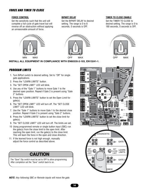
FORCE AND TIMER TO CLOSE<br />
FORCE CONTROL<br />
Set the sensitivity such that the unit will<br />
complete a full cycle of gate travel but will<br />
reverse off an obstruction without applying<br />
an unreasonable amount of force.<br />
BIPART DELAY<br />
Set the BIPART DELAY to <strong>de</strong>sired<br />
setting. The range is 0 to 8<br />
seconds, 0 seconds is OFF.<br />
MIN MAX OFF MAX OFF MAX<br />
INSTALL ALL EQUIPMENT IN COMPLIANCE WITH EN60335-2-103, EN13241-1.<br />
PROGRAM LIMITS<br />
1. Turn BiPart switch to <strong>de</strong>sired setting. Set to “Off” for single<br />
gate applications.<br />
2. Press the “LEARN LIMITS” button.<br />
3. The “SET OPEN LIMIT” LED will blink.<br />
4. Use any of the “Gate 1” buttons to move Gate 1 to the<br />
<strong>de</strong>sired open position. Repeat if Gate 2 is present using “Gate<br />
2” buttons.<br />
5. Press the “LEARN LIMITS” button to set the Open Limit for<br />
gate(s).<br />
6. The “SET OPEN LIMIT” LED will turn off. The “SET CLOSE<br />
LIMIT” LED will blink.<br />
7. Use the “Gate 1” buttons to move Gate 1 to the <strong>de</strong>sired close<br />
position. Repeat if Gate 2 is present using “Gate 2” buttons.<br />
8. Press the “LEARN LIMITS” button to set the close limit for<br />
gate(s).<br />
9. The “SET CLOSE LIMIT” LED will turn off. The limits are set.<br />
10 Using programmed remote or single button input (SBC) run<br />
the gate(s) from the close limit to the open limit. After<br />
reaching the open limit, run the gate(s) to the close limit.<br />
This will learn the force in the open and close direction.<br />
11. If the learned force is not high enough, <strong>manual</strong>ly<br />
adjust the force control as <strong>de</strong>scribed above.<br />
The “Save” Dip switch must be set to OFF to allow programming.<br />
After completion set the “Save” switch back to on.<br />
NOTE: Any following SBC or Remote inputs will move the gate.<br />
14<br />
ALARM<br />
NO<br />
C<br />
MAGLOCK<br />
NO<br />
C<br />
NC<br />
Z1<br />
GATE 1<br />
ACCESSORY<br />
POWER<br />
GATE 2<br />
R4 C2<br />
J4<br />
BRN<br />
GRN<br />
WHT<br />
YEL<br />
BLU<br />
RED<br />
Z12<br />
BRN<br />
24V<br />
GRN<br />
WHT<br />
YEL<br />
BLU<br />
RED<br />
10A 32V<br />
R9Ø<br />
D15<br />
R196<br />
24 VAC/<br />
SOLAR<br />
INPUT<br />
D1Ø<br />
MOV2<br />
SET<br />
OPEN<br />
LIMIT<br />
K6<br />
10A 32V<br />
F3<br />
K2<br />
K1 Q9<br />
R1Ø1<br />
K5<br />
R1ØØ<br />
K4<br />
J19<br />
F5<br />
D21<br />
L1<br />
1<br />
R2<br />
LEARN<br />
R1 XMITTER<br />
F4<br />
2<br />
SET<br />
OPEN<br />
LIMIT<br />
K3<br />
D8<br />
Q22 D22<br />
J1<br />
ACCESSORY<br />
OVLD<br />
MOV1<br />
JMPR2<br />
DB1<br />
OFF<br />
OFF<br />
SINGLE<br />
NO<br />
NO<br />
DIAGNOSTIC<br />
C11<br />
FORCE<br />
C64<br />
S1<br />
R9<br />
Ø14GPØ89ØE<br />
Ø14LGØ89ØE<br />
Ø14SKØ89ØE<br />
BIPART<br />
DELAY<br />
JMPR1<br />
P2<br />
D4<br />
D2<br />
P1<br />
U4<br />
J18<br />
TIMER TO<br />
CLOSE<br />
MIN MAX OFF MAX OFF MAX<br />
C12<br />
U2<br />
ON SAVE<br />
ON MAGLOCK<br />
DUAL MODE<br />
NC EDGE<br />
NC PHOTO<br />
O 1 2 3 4 5<br />
N<br />
GATE 1<br />
SET<br />
LEARN<br />
CLOSE<br />
LIMITS<br />
LIMIT<br />
R35<br />
D9<br />
D27 Z3<br />
Z4<br />
DIAGNOSTIC<br />
TIMER TO CLOSE ENABLE<br />
Set the TIMER TO CLOSE to<br />
<strong>de</strong>sired setting. The range is 0 to<br />
180 seconds, 0 seconds is OFF.<br />
TIMER<br />
GATE 2<br />
RUNNING<br />
U3<br />
D6<br />
D1<br />
FORCE<br />
F7<br />
C13<br />
F6<br />
F2<br />
SET<br />
CLOSE<br />
LIMIT<br />
R2Ø7<br />
R224<br />
SINGLE<br />
BUTTON<br />
C4<br />
Z2Ø<br />
R227<br />
R223<br />
Z22<br />
R92<br />
R91<br />
R94<br />
R93<br />
OPEN<br />
SINGLE BUTTON<br />
RESET<br />
STOP<br />
COM<br />
COM<br />
POWER<br />
SHADOW<br />
INTERRUPT<br />
CHGR COM<br />
OVLD<br />
FUSE<br />
OPEN<br />
F1 20A 32V<br />
GATE 1<br />
LEARN<br />
LIMITS<br />
GATE 2<br />
24V<br />
COM OVLD<br />
OVLD<br />
BATT 2 BATT 1<br />
CLOSE<br />
EDGE<br />
OPEN EDGE/<br />
PHOTO<br />
Z9<br />
OPEN<br />
PHOTO<br />
Z8<br />
CLOSE<br />
PHOTO<br />
SWITCHED<br />
ACCESSORY<br />
POWER<br />
CONTROL<br />
INPUTS<br />
LOOP<br />
INPUTS