owner's manual model cb24 bedienungsanleitung ... - liftmaster.de
owner's manual model cb24 bedienungsanleitung ... - liftmaster.de
owner's manual model cb24 bedienungsanleitung ... - liftmaster.de

Erfolgreiche ePaper selbst erstellen
Machen Sie aus Ihren PDF Publikationen ein blätterbares Flipbook mit unserer einzigartigen Google optimierten e-Paper Software.
To reduce the risk of SEVERE INJURY or DEATH:<br />
• ANY maintenance to the operator or in the area near the<br />
operator MUST not be performed until disconnecting the<br />
electrical power and locking-out the power via the operator<br />
power switch. Upon completion of maintenance the area MUST<br />
be cleared and secured, at that time the unit may be returned<br />
to service.<br />
• Disconnecting power at the fuse box BEFORE proceeding.<br />
Operator MUST be properly groun<strong>de</strong>d and connected in<br />
accordance with local electrical co<strong>de</strong>s. NOTE: The operator<br />
should be on a separate fused line of a<strong>de</strong>quate capacity.<br />
• ALL electrical connections MUST be ma<strong>de</strong> by a qualified<br />
individual.<br />
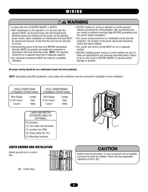
NOTE: Calculated using NEC gui<strong>de</strong>lines. Local co<strong>de</strong>s and conditions must be reviewed for suitability of wire installation.<br />
230Vac POWER WIRE<br />
(STRANDED COPPER WIRE)<br />
Wire Gauge<br />
0.75/1.5mm2 1.5mm2 Length<br />
50m<br />
100m<br />
WIRING<br />
All power wiring should be on a <strong>de</strong>dicated circuit and well protected.<br />
EARTH GROUND ROD INSTALLATION<br />
Attach ground wire to control<br />
box.<br />
24Vac TRANSFORMER<br />
(STRANDED COPPER WIRE)<br />
Wire Gauge<br />
0.75/1.5mm2 1.5mm2 LA400-JB40 MOTOR<br />
EXTENSION CABLE KIT<br />
(OPTIONAL)<br />
Kit Contains:<br />
(1) 12m cable with terminals<br />
(1) Junction box IP65<br />
(2) Strain reliefs PG 13,5<br />
(1) Mounting hardware<br />
(1) Control Box<br />
1<br />
Length<br />
50m<br />
100m<br />
6<br />
• DO NOT install any wiring or attempt to run the operator<br />
without consulting the wiring diagram. We recommend that<br />
you Install an optional reversing edge BEFORE proceeding with<br />
the control station installation.<br />
• ALL power wiring should be on a <strong>de</strong>dicated circuit and well<br />
protected. The location of the power disconnect should be<br />
visible and clearly labeled.<br />
• ALL power and control wiring MUST be run in separate<br />
conduit.<br />
• BEFORE installing power wiring or control stations be sure to<br />
follow all specifications and warnings <strong>de</strong>scribed below. Failure<br />
to do so may result in SEVERE INJURY to persons and/or<br />
damage to operator.<br />
1<br />
System must be groun<strong>de</strong>d. In case no ground wire is available<br />
a ground rod must be installed. Follow the local applicable<br />
standards of EN or IEC.<br />
2<br />
3