owner's manual model cb24 bedienungsanleitung ... - liftmaster.de
owner's manual model cb24 bedienungsanleitung ... - liftmaster.de
owner's manual model cb24 bedienungsanleitung ... - liftmaster.de

Sie wollen auch ein ePaper? Erhöhen Sie die Reichweite Ihrer Titel.
YUMPU macht aus Druck-PDFs automatisch weboptimierte ePaper, die Google liebt.
OPERATOR IS DEAD<br />
When power is supplied to<br />
the control board, no LED<br />
turns ON.<br />
OPERATOR DOES NOT RUN<br />
Unit does not respond to a<br />
Radio command.<br />
OPERATOR DOES NOT RUN<br />
Unit does not respond to<br />
SBC command.<br />
MOTOR DOES NOT RUN<br />
Relays ‘click’ when Radio<br />
or SBC signal is given, but<br />
the operator does not<br />
move.<br />
GATE STOPS AND<br />
REVERSES RIGHT AFTER<br />
IT STARTS MOVING<br />
GATE STOPS RUNNING<br />
RIGHT AFTER IT STARTS<br />
MOVING (BATTERY RUN)<br />
GATE OPENS BUT DOES<br />
NOT CLOSE<br />
GATE LOSES LIMITS<br />
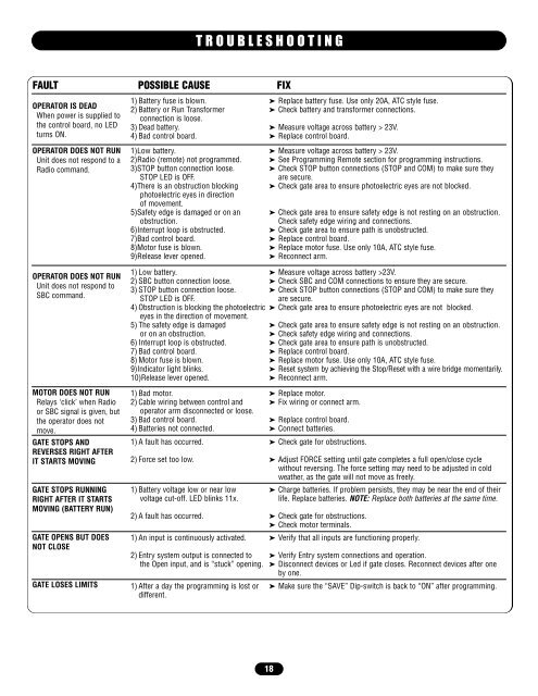
TROUBLESHOOTING<br />
FAULT POSSIBLE CAUSE FIX<br />
1) Battery fuse is blown. ➤ Replace battery fuse. Use only 20A, ATC style fuse.<br />
2) Battery or Run Transformer ➤ Check battery and transformer connections.<br />
connection is loose.<br />
3) Dead battery. ➤ Measure voltage across battery > 23V.<br />
4) Bad control board. ➤ Replace control board.<br />
1)Low battery. ➤ Measure voltage across battery > 23V.<br />
2)Radio (remote) not programmed. ➤ See Programming Remote section for programming instructions.<br />
3)STOP button connection loose. ➤ Check STOP button connections (STOP and COM) to make sure they<br />
STOP LED is OFF. are secure.<br />
4)There is an obstruction blocking ➤ Check gate area to ensure photoelectric eyes are not blocked.<br />
photoelectric eyes in direction<br />
of movement.<br />
5)Safety edge is damaged or on an ➤ Check gate area to ensure safety edge is not resting on an obstruction.<br />
obstruction. Check safety edge wiring and connections.<br />
6)Interrupt loop is obstructed. ➤ Check gate area to ensure path is unobstructed.<br />
7)Bad control board. ➤ Replace control board.<br />
8)Motor fuse is blown. ➤ Replace motor fuse. Use only 10A, ATC style fuse.<br />
9)Release lever opened. ➤ Reconnect arm.<br />
1) Low battery. ➤ Measure voltage across battery >23V.<br />
2) SBC button connection loose. ➤ Check SBC and COM connections to ensure they are secure.<br />
3) STOP button connection loose. ➤ Check STOP button connections (STOP and COM) to make sure they<br />
STOP LED is OFF. are secure.<br />
4) Obstruction is blocking the photoelectric ➤ Check gate area to ensure photoelectric eyes are not blocked.<br />
eyes in the direction of movement.<br />
5) The safety edge is damaged ➤ Check gate area to ensure safety edge is not resting on an obstruction.<br />
or on an obstruction. ➤ Check safety edge wiring and connections.<br />
6) Interrupt loop is obstructed. ➤ Check gate area to ensure path is unobstructed.<br />
7) Bad control board. ➤ Replace control board.<br />
8) Motor fuse is blown. ➤ Replace motor fuse. Use only 10A, ATC style fuse.<br />
9)Indicator light blinks. ➤ Reset system by achieving the Stop/Reset with a wire bridge momentarily.<br />
10)Release lever opened. ➤ Reconnect arm.<br />
1) Bad motor. ➤ Replace motor.<br />
2) Cable wiring between control and<br />
operator arm disconnected or loose.<br />
➤ Fix wiring or connect arm.<br />
3) Bad control board. ➤ Replace control board.<br />
4) Batteries not connected. ➤ Connect batteries.<br />
1) A fault has occurred. ➤ Check gate for obstructions.<br />
2) Force set too low. ➤ Adjust FORCE setting until gate completes a full open/close cycle<br />
without reversing. The force setting may need to be adjusted in cold<br />
weather, as the gate will not move as freely.<br />
1) Battery voltage low or near low ➤ Charge batteries. If problem persists, they may be near the end of their<br />
voltage cut-off. LED blinks 11x. life. Replace batteries. NOTE: Replace both batteries at the same time.<br />
2) A fault has occurred. ➤ Check gate for obstructions.<br />
➤ Check motor terminals.<br />
1) An input is continuously activated. ➤ Verify that all inputs are functioning properly.<br />
2) Entry system output is connected to ➤ Verify Entry system connections and operation.<br />
the Open input, and is “stuck” opening. ➤ Disconnect <strong>de</strong>vices or Led if gate closes. Reconnect <strong>de</strong>vices after one<br />
by one.<br />
1) After a day the programming is lost or ➤ Make sure the “SAVE” Dip-switch is back to “ON” after programming.<br />
different.<br />
18