owner's manual model cb24 bedienungsanleitung ... - liftmaster.de
owner's manual model cb24 bedienungsanleitung ... - liftmaster.de
owner's manual model cb24 bedienungsanleitung ... - liftmaster.de

Sie wollen auch ein ePaper? Erhöhen Sie die Reichweite Ihrer Titel.
YUMPU macht aus Druck-PDFs automatisch weboptimierte ePaper, die Google liebt.
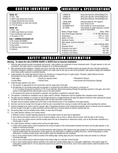
CARTON INVENTORY<br />
CB24K KIT<br />
1x PVC – Box<br />
1x CB24-Logic Board (pre-mount)<br />
1x Charge transformer (pre-mount)<br />
2x 12Volt Batteries & wires (pre-mount)<br />
1x 771E IR-sensor<br />
CB24R KIT<br />
1x PVC – Box<br />
1x CB24-Logic Board (pre-mount)<br />
1x Run transformer (pre-mount)<br />
1x IR-sensor (771E)<br />
CAK-1 COMMON ACCESSORY KIT<br />
1x RF module 433.92MHz<br />
2x Transmitter 3-channel 94335E<br />
1x Key switch<br />
1x Flashing Light (FLA24-2)<br />
1x Antenna<br />
INVENTORY & SPECIFICATIONS<br />
LYN300-24 Wing Gate Operator 24Volt/250kg/2.5m<br />
LYN400-24 Wing Gate Operator 24Volt/250kg/4.0m<br />
SCS300-24 Wing Gate Operator 24Volt/250kg/3.0m<br />
LA400-JB40 Extensioncable Kit 12m (page 6)<br />
600206-24 Solar Panel 24 Volt<br />
041ASWG-0479 Post bracket for round posts/piece<br />
50-19503 Post bracket for gates opening to outsi<strong>de</strong><br />
(push to open)/piece<br />
Battery Charger Supply . . . . . . . . . . . . . . . . . . . . . . . . .26Vac, 29VA<br />
Solar Panel Supply (Optional) . . . . . . . . . . . . .27.4V, 9W (Minimum)<br />
Temperature . . . . . . . . . . . . . . . . . . . . . . . . . . . . . . . .-20oC to + 55oC Battery 12V/7AH . . . . . . . . . . . . . . . . . . . . . . . . . . . .-15oC to + 55oC Electronic Control . . . . . . . . . . . . . . . . . . . . . . . . . . . . . . . . . . . .IP44<br />
Main Supply (Control) Dedicated<br />
Circuit . . . . . . . . . . . . . . . . . . . . . . . . . . . . . . . .230V~240V/50~60Hz<br />
Absorbed Power . . . . . . . . . . . . . . . . . . . . . . . . . . . . . . . .0.75 Watts<br />
Protection Fuse Gate 1 . . . . . . . . . . . . . . . . . . . . . . . . . . . . .ATC 10A<br />
Protection Fuse Gate 2 . . . . . . . . . . . . . . . . . . . . . . . . . . . . .ATC 10A<br />
Protection Fuse Battery . . . . . . . . . . . . . . . . . . . . . . . . . . . .ATC 20A<br />
SAFETY INSTALLATION INFORMATION<br />
Warning - To reduce the risk of SEVERE INJURY or DEATH from an incorrect installation:<br />
1. Vehicular gate systems provi<strong>de</strong> convenience and security. Gate systems are comprised of many component parts. The gate operator is only one<br />
component. Each gate system is specifically <strong>de</strong>signed for an individual application.<br />
2. Gate operating system <strong>de</strong>signers, installers and users must take into account the possible hazards associated with each individual application.<br />
Improperly <strong>de</strong>signed, installed or maintained systems can create risks for the user as well as the bystan<strong>de</strong>r. Gate systems <strong>de</strong>sign and installation<br />
must reduce public exposure to potential hazards.<br />
3. A gate operator can create high levels of force in its function as a component part of a gate system. Therefore, safety features must be<br />
incorporated into every <strong>de</strong>sign. Specific safety features inclu<strong>de</strong>:<br />
• Gate Edges • Guards for exposed rollers • Photoelectric Sensors<br />
• Screen Mesh • Vertical Posts • Instructional and Precautionary Signage<br />
4. Install the gate operator only when:<br />
a. The operator is appropriate for the construction and the usage class of the gate.<br />
b. All openings of a horizontal swing gate are guar<strong>de</strong>d or screened from the bottom of the gate to a minimum of<br />
4' (1.2 m) above the ground to prevent a 2 1/4" (6 cm) diameter sphere from passing through the openings anywhere in the gate, and in that<br />
portion of the adjacent fence that the gate covers in the open position.<br />
c. All exposed pinch points are eliminated or guar<strong>de</strong>d, and guarding is supplied for exposed rollers.<br />
5. The operator is inten<strong>de</strong>d for installation only on gates used for vehicles. Pe<strong>de</strong>strians must be supplied with a separate access opening.<br />
6. The gate must be installed in a location so that enough clearance is supplied between the gate and adjacent structures when opening and closing<br />
to reduce the risk of entrapment. Swinging gates shall not open into public access areas.<br />
7. The gate must be properly installed and work freely in both directions prior to the installation of the gate operator.<br />
8. Controls must be far enough from the gate so that the user is prevented from coming in contact with the gate while operating the controls.<br />
9. Controls inten<strong>de</strong>d to be used to reset an operator after 2 sequential activations of the entrapment protection <strong>de</strong>vice or <strong>de</strong>vices must be located in<br />
the line of sight of the gate, or easily accessible controls shall have a security feature to prevent unauthorized use.<br />
10. All warning signs must be installed where visible, on each si<strong>de</strong> of the gate.<br />
11. For a gate operator utilizing a non-contact sensor:<br />
a. Reference owner’s <strong>manual</strong> regarding placement of non-contact sensor for each type of application.<br />
b. Care shall be exercised to reduce the risk of nuisance tripping, such as when a vehicle trips the sensor while the gate is still moving.<br />
c. One or more non-contact sensors shall be located where the risk of entrapment or obstruction exists, such as the perimeter reachable by a<br />
moving gate or barrier.<br />
12. For a gate operator utilizing a contact sensor such as an edge sensor:<br />
a. A hard wired contact sensor shall be located and its wiring arranged so the communication between the sensor and the gate operator is not<br />
subject to mechanical damage.<br />
b. A wireless contact sensor such as the one that transmits radio frequency (RF) signals to the gate operator for entrapment protection functions<br />
shall be located where the transmission of the signals are not obstructed or impe<strong>de</strong>d by building structures, natural landscaping or similar<br />
obstruction. A wireless contact sensor shall function un<strong>de</strong>r the inten<strong>de</strong>d end-use conditions.<br />
c. One or more contact sensors shall be located at the leading edge, trailing edge and post mounted both insi<strong>de</strong> and outsi<strong>de</strong> of a vehicular<br />
horizontal sli<strong>de</strong> gate.<br />
d. One or more contact sensors shall be located at the bottom edge of a vehicular vertical lift gate.<br />
e. One or more contact sensors shall be located on the insi<strong>de</strong> and outsi<strong>de</strong> leading edge of a swing gate. Additionally, if the bottom edge of a<br />
swing gate is greater than 6" (15 cm) above the ground at any point in its arc of travel, one or more contact sensors shall be located on the<br />
bottom edge.<br />
3