G&D DVICenter - Guntermann und Drunck GmbH
G&D DVICenter - Guntermann und Drunck GmbH
G&D DVICenter - Guntermann und Drunck GmbH

Sie wollen auch ein ePaper? Erhöhen Sie die Reichweite Ihrer Titel.
YUMPU macht aus Druck-PDFs automatisch weboptimierte ePaper, die Google liebt.
<strong>Guntermann</strong> & <strong>Drunck</strong> <strong>GmbH</strong><br />
www.gdsys.de<br />
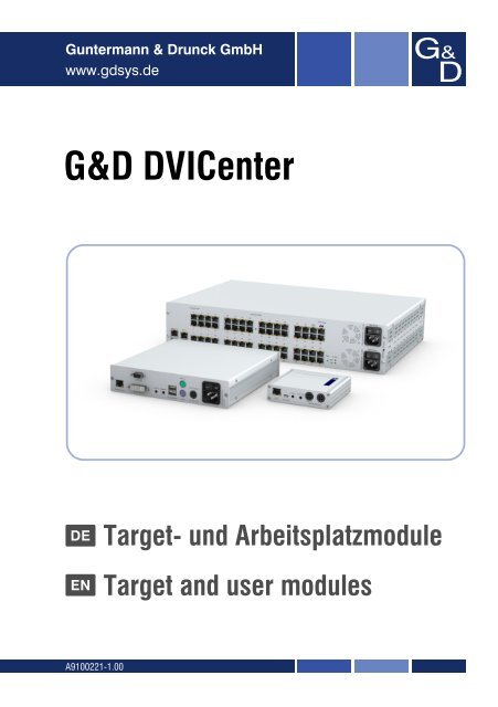
G&D <strong>DVICenter</strong><br />
DE Target- <strong>und</strong> Arbeitsplatzmodule<br />
EN Target and user modules<br />
A9100221-1.00
Zu dieser Dokumentation<br />
Diese Dokumentation wurde mit größter Sorgfalt erstellt <strong>und</strong> nach dem Stand der<br />
Technik auf Korrektheit überprüft.<br />
Für die Qualität, Leistungsfähigkeit sowie Marktgängigkeit des G&D-Produkts zu<br />
einem bestimmten Zweck, der von dem durch die Produktbeschreibung abgedeckten<br />
Leistungsumfang abweicht, übernimmt G&D weder ausdrücklich noch stillschweigend<br />
die Gewähr oder Verantwortung.<br />
Für Schäden, die sich direkt oder indirekt aus dem Gebrauch der Dokumentation<br />
ergeben, sowie für beiläufige Schäden oder Folgeschäden ist G&D nur im Falle des<br />
Vorsatzes oder der groben Fahrlässigkeit verantwortlich.<br />
Gewährleistungsausschluss<br />
G&D übernimmt keine Gewährleistung für Geräte, die<br />
nicht bestimmungsgemäß eingesetzt wurden.<br />
nicht autorisiert repariert oder modifiziert wurden.<br />
schwere äußere Beschädigungen aufweisen, welche nicht bei Lieferungserhalt<br />
angezeigt wurden.<br />
durch Fremdzubehör beschädigt wurden.<br />
G&D haftet nicht für Folgeschäden jeglicher Art, die möglicherweise durch den<br />
Einsatz der Produkte entstehen können.<br />
Warenzeichennachweis<br />
Alle Produkt- <strong>und</strong> Markennamen, die in diesem Handbuch oder in den übrigen<br />
Dokumentationen zu Ihrem G&D-Produkt genannt werden, sind Warenzeichen<br />
oder eingetragene Warenzeichen der entsprechenden Rechtsinhaber.<br />
Impressum<br />
© <strong>Guntermann</strong> & <strong>Drunck</strong> <strong>GmbH</strong> 2013. Alle Rechte vorbehalten.<br />
Version 1.00 – 06.02.2013<br />
<strong>Guntermann</strong> & <strong>Drunck</strong> <strong>GmbH</strong><br />
Dortm<strong>und</strong>er Str. 4a<br />
57234 Wilnsdorf<br />
Germany<br />
Telefon +49 (0) 2739 8901-100<br />
Telefax +49 (0) 2739 8901-120<br />
http://www.GDsys.de<br />
sales@GDsys.de<br />
i · G&D <strong>DVICenter</strong>
Inhaltsverzeichnis<br />
Inhaltsverzeichnis<br />
Sicherheitshinweise .......................................................................................... 1<br />
Kapitel 1: Target-Module<br />
Das Target-Modul »DVI-CPU« ........................................................................ 2<br />
Das Target-Modul »DVI-CPU-UC« ................................................................. 6<br />
Das Target-Modul »DVI-CPU-MC2« ............................................................. 10<br />
Das Target-Modul »DVI-CPU-MC2-UC« ...................................................... 15<br />
Das Target-Modul »DVI-DP-CPU« ................................................................ 21<br />
Das Target-Modul »DVI-DP-CPU-UC« ......................................................... 26<br />
Das Target-Modul »U2-R-CPU« .................................................................... 30<br />
Kapitel 2: Arbeitplatzmodule<br />
Das Arbeitsplatzmodul »DVI-CON« .............................................................. 33<br />
Das Arbeitsplatzmodul »DVI-CON-MC2« ..................................................... 38<br />
Das Arbeitsplatzmodul »DVI-CON-MC4« ..................................................... 44<br />
Das Arbeitsplatzmodul »DVI-CON-Video« ..................................................... 52<br />
Das Arbeitsplatzmodul »DVI-CON-12V« ....................................................... 57<br />
Das Arbeitsplatzmodul »U2-R-CON« .............................................................. 63<br />
G&D <strong>DVICenter</strong> · ii
Sicherheitshinweise<br />
Sicherheitshinweise<br />
Bitte lesen Sie die folgenden Sicherheitshinweise aufmerksam durch, bevor Sie das<br />
G&D-Produkt in Betrieb nehmen. Die Hinweise helfen Schäden am Produkt zu vermeiden<br />
<strong>und</strong> möglichen Verletzungen vorzubeugen.<br />
Halten Sie diese Sicherheitshinweise für alle Personen griffbereit, die dieses Produkt<br />
benutzen werden.<br />
Befolgen Sie alle Warnungen oder Bedienungshinweise, die sich am Gerät oder in<br />
dieser Bedienungsanleitung befinden.<br />
, Vorsicht vor Stromschlägen<br />
Um das Risiko eines Stromschlags zu vermeiden, sollten Sie das Gerät nicht öffnen<br />
oder Abdeckungen entfernen. Im Servicefall wenden Sie sich bitte an unsere<br />
Techniker.<br />
, Ziehen Sie den Netzstecker des Geräts vor Installationsarbeiten<br />
Stellen Sie vor Installationsarbeiten sicher, dass das Gerät spannungsfrei ist. Ziehen<br />
Sie den Netzstecker oder die Spannungsversorgung am Gerät ab.<br />
, Ständigen Zugang zu den Netzsteckern der Geräte sicherstellen<br />
Achten Sie bei der Installation der Geräte darauf, dass die Netzstecker der<br />
Geräte jederzeit zugänglich bleiben.<br />
, Lüftungsöffnungen nicht verdecken<br />
Lüftungsöffnungen verhindern eine Überhitzung des Geräts. Verdecken Sie<br />
diese nicht.<br />
! Stolperfallen vermeiden<br />
Vermeiden Sie bei der Verlegung der Kabel Stolperfallen.<br />
, Geerdete Spannungsquelle verwenden<br />
Betreiben Sie dieses Gerät nur an einer geerdeten Spannungsquelle.<br />
, Verwenden Sie ausschließlich das G&D-Netzteil<br />
Betreiben Sie dieses Gerät nur mit dem mitgelieferten oder in der Bedienungsanleitung<br />
aufgeführten Netzteil.<br />
! Betreiben Sie das Gerät ausschließlich im vorgesehenen Einsatzbereich<br />
Die Geräte sind für eine Verwendung im Innenbereich ausgelegt. Vermeiden Sie<br />
extreme Kälte, Hitze oder Feuchtigkeit.<br />
1 · G&D <strong>DVICenter</strong>
A Target-Module<br />
Das Target-Modul »DVI-CPU«<br />
Mit dem Target-Modul DVI-CPU integrieren Sie einen Computer in ein kompatibles<br />
KVM-Matrixsystem.<br />
Hierzu verbinden Sie zunächst den Computer mit dem Target-Modul. Anschließend<br />
verbinden Sie das Target-Modul mit einem Zentralmodul der <strong>DVICenter</strong>-Serie.<br />
Die Arbeitsplätze des KVM-Matrixsystems können sich auf das Target-Modul aufschalten<br />
<strong>und</strong> den angeschlossenen Computer bedienen.<br />
HINWEIS: Der über das Target-Modul am KVM-Matrixsystem angeschlossene<br />
Computer wird innerhalb des Systems als Target bezeichnet.<br />
Lieferumfang<br />
1 × Target-Modul DVI-CPU<br />
1 × Videokabel (DVI-D-SL)<br />
1 × USB-Gerätekabel<br />
1 × Twin-PS/2-Kabel<br />
2 × Audio-Kabel<br />
1 × Netzteil (12V/24W)<br />
1 × Stromversorgungskabel<br />
Erforderliches Zubehör<br />
Ein Twisted-Pair-Kabel der Kategorie 5e (oder höher) zum Anschluss des Target-<br />
Moduls an das Zentralmodul.<br />
G&D <strong>DVICenter</strong> · 2
Das Target-Modul »DVI-CPU«<br />
Installation<br />
Anschluss des Target-Computers<br />
Keyb. Mouse USB K/M DVI-D CPU<br />
HINWEIS: Die Tastatur- <strong>und</strong> Maus-Signale können wahlweise über die PS/2-<br />
Schnittstellen oder die USB-Schnittstelle an den Computer übertragen werden.<br />
Keyb.: Verbinden Sie die PS/2-Tastatur-Schnittstelle des Computers mit dieser Schnittstelle.<br />
Verwenden Sie hierzu den violetten Stecker des PS/2-Twin-Kabels.<br />
Mouse: Verbinden Sie die PS/2-Maus-Schnittstelle des Computers mit dieser Schnittstelle.<br />
Verwenden Sie hierzu den grünen Stecker des PS/2-Twin-Kabels.<br />
USB K/M: Verbinden Sie eine USB-Schnittstelle des Computers mit dieser Schnittstelle.<br />
Verwenden Sie hierzu das USB-Gerätekabel.<br />
DVI-D CPU: Verbinden Sie den digitalen Videoausgang des Computers mit dieser<br />
Schnittstelle. Verwenden Sie hierzu das Videokabel.<br />
<br />
Line In: Verbinden Sie die Line-Out-Schnittstelle des Computers mit dieser Schnittstelle.<br />
Verwenden Sie hierzu eines der Audio-Kabel.<br />
Line Out: Verbinden Sie die Line-In-Schnittstelle des Computers mit dieser Schnittstelle.<br />
Verwenden Sie hierzu eines der Audio-Kabel.<br />
Verbindung zum Zentralmodul<br />
Trans.: Verbinden Sie die Trans.-Schnittstellen der einzelnen Target-Module mit<br />
jeweils einem Dynamic Port, der zum Anschluss eines Target-Moduls konfiguriert ist.<br />
Verwenden Sie hierzu eine Twisted-Pair-Verkabelung der Kategorie 5e (oder höher).<br />
HINWEIS: Beachten Sie die Hinweise im Abschnitt Anschluss der Target-Module an<br />
das Zentralmodul im Installationshandbuch des Matrixswitches.<br />
HINWEIS: Eine direkte Verbindung zwischen einem Target- <strong>und</strong> einem Arbeitsplatzmodul<br />
ist möglich. Verwenden Sie zur Verbindung der beiden Module ein Crossover-<br />
Kabel der Kategorie 5e (oder höher).<br />
3 · G&D <strong>DVICenter</strong>
Stromversorgung<br />
Das Target-Modul »DVI-CPU«<br />
Power In: Stecken Sie das Anschlusskabel des Netzteils in diese Schnittstelle. Verbinden<br />
Sie anschließend das Stromversorgungskabel mit dem Netzteil <strong>und</strong> einer Netzsteckdose.<br />
Statusanzeigen<br />
Die LED an der Rückseite des Arbeitsplatzmoduls signalisiert den Status der Stromversorgung:<br />
LED Status Bedeutung<br />
Power an Das externe Netzteil ist angeschlossen <strong>und</strong> eine Spannung von 12 Volt<br />
verfügbar.<br />
aus Das externe Netzteil ist nicht (korrekt) angeschlossen.<br />
Das Blinken der Transmission-LEDs signalisiert folgende Betriebszustände:<br />
LED Status Bedeutung<br />
gelb aus Es ist kein Arbeitsplatzmodul auf das Target-Modul aufgeschaltet.<br />
an Ein Arbeitsplatzmodul ist auf das Target-Modul aufgeschaltet.<br />
blinkt Das eingehende Videosignal wurde nicht erkannt.<br />
blitzt Keine Spannung auf der PS/2-Schnittstelle bzw. dem USB-Bus vorhanden.<br />
grün aus Das Target-Modul ist ausgeschaltet.<br />
blinkt Das Netzteil ist angeschlossen <strong>und</strong> liefert die erforderliche Spannung.<br />
Die Verbindung zum Zentralmodul kann nicht hergestellt werden.<br />
blitzt Die Verbindung zum Zentralmodul wurde hergestellt.<br />
Es ist kein Arbeitsplatzmodul aufgeschaltet oder der Rechner ist aus.<br />
an Ein Arbeitsplatzmodul ist auf das Target-Modul aufgeschaltet.<br />
Ein Rechner ist angeschlossen <strong>und</strong> eingeschaltet.<br />
flackert Tastatur- <strong>und</strong> Mauseingaben werden vom aufgeschalteten<br />
Arbeitsplatzmodul übertragen.<br />
Der Rhythmus des Flackerns wird durch die Eingaben des Anwenders<br />
bestimmt.<br />
G&D <strong>DVICenter</strong> · 4
Das Target-Modul »DVI-CPU«<br />
Technische Daten<br />
DVI-CPU<br />
Schnittstellen zum Video: 1 × DVI-D (Single Link)<br />
Computer<br />
Tastatur- <strong>und</strong> Maussignale: 2 × PS/2-Buchse<br />
1 × USB-B<br />
Audio: 2 × 3,5 mm-Klinkenbuchse<br />
Datenübertragung Schnittstelle: 1 × RJ45-Buchse<br />
zum Zentralmodul<br />
Übertragungslänge: max. 140 Meter<br />
Video Auflösung @ 60 Hz: max. 1920 × 1200 Bildpunkte<br />
Farbtiefe: 24 Bit<br />
Pixelrate: 25 MHz bis 165 MHz<br />
Vertikalfrequenz: 50 Hz bis 180 Hz<br />
Horizontalfrequenz: 30 kHz bis 130 kHz<br />
Normen: DVI 1.0, E-DDC<br />
Audio Typ: bi-direktionale Verlängerung<br />
Auflösung: 24 Bit<br />
Abtastrate: 96 kHz<br />
Bandbreite: 22 kHz<br />
Stromversorgung Typ: Tischnetzteil (12 V/2 A)<br />
Anschluss: 1 × Mini-DIN 4-Buchse<br />
Stromaufnahme: max. 500 mA @ 12 VDC<br />
Gehäuse Material: Aluminium eloxiert<br />
Maße (B × H × T): 105 × 26 × 104 mm<br />
Gewicht: ca. 240 g<br />
Einsatzumgebung Temperatur: +5 bis +45 °C<br />
Luftfeuchte: < 80%, nicht kondensierend<br />
Konformität CE, RoHS<br />
5 · G&D <strong>DVICenter</strong>
Das Target-Modul »DVI-CPU-UC«<br />
Das Target-Modul »DVI-CPU-UC«<br />
Mit dem Target-Modul DVI-CPU-UC integrieren Sie einen Computer in zwei verschiedene<br />
KVM-Matrixsysteme.<br />
Hierzu verbinden Sie zunächst den Computer mit dem Target-Modul. Anschließend<br />
verbinden Sie das Target-Modul mit zwei Zentralmodulen der <strong>DVICenter</strong>-Serie.<br />
Die Arbeitsplätze der KVM-Matrixsysteme können sich auf das Target-Modul aufschalten<br />
<strong>und</strong> den angeschlossenen Computer bedienen.<br />
HINWEIS: Der über das Target-Modul am KVM-Matrixsystem angeschlossene<br />
Computer wird innerhalb des Systems als Target bezeichnet.<br />
Lieferumfang<br />
1 × Target-Modul DVI-CPU-UC<br />
1 × Videokabel (DVI-D-SL)<br />
1 × USB-Gerätekabel<br />
1 × Twin-PS/2-Kabel<br />
2 × Audio-Kabel<br />
1 × Netzteil (12V/2A)<br />
1 × Stromversorgungskabel<br />
Erforderliches Zubehör<br />
Zwei Twisted-Pair-Kabel der Kategorie 5e (oder höher) zum Anschluss des Target-<br />
Moduls an zwei Zentralmodule.<br />
G&D <strong>DVICenter</strong> · 6
Das Target-Modul »DVI-CPU-UC«<br />
Installation<br />
Anschluss des Target-Computers<br />
Keyb. Mouse USB K/M DVI-D CPU<br />
HINWEIS: Die Tastatur- <strong>und</strong> Maus-Signale können wahlweise über die PS/2-<br />
Schnittstellen oder die USB-Schnittstelle an den Computer übertragen werden.<br />
Keyb.: Verbinden Sie die PS/2-Tastatur-Schnittstelle des Computers mit dieser Schnittstelle.<br />
Verwenden Sie hierzu den violetten Stecker des PS/2-Twin-Kabels.<br />
Mouse: Verbinden Sie die PS/2-Maus-Schnittstelle des Computers mit dieser Schnittstelle.<br />
Verwenden Sie hierzu den grünen Stecker des PS/2-Twin-Kabels.<br />
USB K/M: Verbinden Sie eine USB-Schnittstelle des Computers mit dieser Schnittstelle.<br />
Verwenden Sie hierzu das USB-Gerätekabel.<br />
DVI-D CPU: Verbinden Sie den digitalen Videoausgang des Computers mit dieser<br />
Schnittstelle. Verwenden Sie hierzu das Videokabel.<br />
<br />
<br />
Line In: Verbinden Sie die Line-Out-Schnittstelle des Computers mit dieser Schnittstelle.<br />
Verwenden Sie hierzu eines der Audio-Kabel.<br />
Line Out: Verbinden Sie die Line-In-Schnittstelle des Computers mit dieser Schnittstelle.<br />
Verwenden Sie hierzu eines der Audio-Kabel.<br />
Verbindung zum Zentralmodul<br />
WICHTIG: Verbinden Sie pro Zentralmodul ausschließlich eine Transmission-<br />
Schnittstelle des Target-Moduls!<br />
Trans. 1: Verbinden Sie die Schnittstelle mit einem Dynamic Port eines Zentralmoduls,<br />
der zum Anschluss eines Target-Moduls konfiguriert ist.<br />
Verwenden Sie hierzu eine Twisted-Pair-Verkabelung der Kategorie 5e (oder höher).<br />
Trans. 2: Verbinden Sie die Schnittstelle mit einem Dynamic Port eines anderen Zentralmoduls,<br />
der zum Anschluss eines Target-Moduls konfiguriert ist.<br />
Verwenden Sie hierzu eine Twisted-Pair-Verkabelung der Kategorie 5e (oder höher).<br />
7 · G&D <strong>DVICenter</strong>
Stromversorgung<br />
Das Target-Modul »DVI-CPU-UC«<br />
HINWEIS: Beachten Sie die Hinweise im Abschnitt Anschluss der Target-Module an<br />
das Zentralmodul im Installationshandbuch des Matrixswitches.<br />
HINWEIS: Eine direkte Verbindung zwischen einem Target- <strong>und</strong> einem Arbeitsplatzmodul<br />
ist möglich. Verwenden Sie zur Verbindung der beiden Module ein Crossover-<br />
Kabel der Kategorie 5e (oder höher).<br />
Power In: Stecken Sie das Anschlusskabel des Netzteils in diese Schnittstelle. Verbinden<br />
Sie anschließend das Stromversorgungskabel mit dem Netzteil <strong>und</strong> einer Netzsteckdose.<br />
Statusanzeigen<br />
Die LED an der Rückseite des Arbeitsplatzmoduls signalisiert den Status der Stromversorgung:<br />
LED Status Bedeutung<br />
Power an Das externe Netzteil ist angeschlossen <strong>und</strong> eine Spannung von 12 Volt<br />
verfügbar.<br />
aus Das externe Netzteil ist nicht (korrekt) angeschlossen.<br />
Das Blinken der Transmission-LEDs signalisiert folgende Betriebszustände der<br />
jeweiligen Verbindung:<br />
LED Status Bedeutung<br />
gelb aus Es ist kein Arbeitsplatzmodul auf das Target-Modul aufgeschaltet.<br />
an Ein Arbeitsplatzmodul ist auf das Target-Modul aufgeschaltet.<br />
blinkt Das eingehende Videosignal wurde nicht erkannt.<br />
blitzt Keine Spannung auf der PS/2-Schnittstelle bzw. dem USB-Bus vorhanden.<br />
grün aus Das Target-Modul ist ausgeschaltet.<br />
blinkt Das Netzteil ist angeschlossen <strong>und</strong> liefert die erforderliche Spannung.<br />
Die Verbindung zum Zentralmodul kann nicht hergestellt werden.<br />
blitzt Die Verbindung zum Zentralmodul wurde hergestellt.<br />
Es ist kein Arbeitsplatzmodul aufgeschaltet oder der Rechner ist aus.<br />
an Ein Arbeitsplatzmodul ist auf das Target-Modul aufgeschaltet.<br />
Ein Rechner ist angeschlossen <strong>und</strong> eingeschaltet.<br />
flackert Tastatur- <strong>und</strong> Mauseingaben werden vom aufgeschalteten<br />
Arbeitsplatzmodul übertragen.<br />
Der Rhythmus des Flackerns wird durch die Eingaben des Anwenders<br />
bestimmt.<br />
G&D <strong>DVICenter</strong> · 8
Das Target-Modul »DVI-CPU-UC«<br />
Technische Daten<br />
DVI-CPU-UC<br />
Schnittstellen zum Video: 1 × DVI-D (Single Link)<br />
Computer<br />
Tastatur- <strong>und</strong> Maussignale: 2 × PS/2-Buchse<br />
1 × USB-B<br />
Audio: 2 × 3,5 mm-Klinkenbuchse<br />
Datenübertragung zu Schnittstelle: 2 × RJ45-Buchse<br />
Zentralmodulen<br />
Übertragungslänge: max. 140 Meter<br />
Video Auflösung @ 60 Hz: max. 1920 × 1200 Bildpunkte<br />
Farbtiefe: 24 Bit<br />
Pixelrate: 25 MHz bis 165 MHz<br />
Vertikalfrequenz: 50 Hz bis 180 Hz<br />
Horizontalfrequenz: 30 kHz bis 130 kHz<br />
Normen: DVI 1.0, E-DDC<br />
Audio Typ: bi-direktionale Verlängerung<br />
Auflösung: 24 Bit<br />
Abtastrate: 96 kHz<br />
Bandbreite: 22 kHz<br />
Stromversorgung Typ: Tischnetzteil (12 V/2 A)<br />
Anschluss: 1 × Mini-DIN 4-Buchse<br />
Stromaufnahme: max. 600 mA @ 12 VDC<br />
Gehäuse Material: Aluminium eloxiert<br />
Maße (B × H × T): 105 × 26 × 104 mm<br />
Gewicht: ca. 260 g<br />
Einsatzumgebung Temperatur: +5 bis +45 °C<br />
Luftfeuchte: < 80%, nicht kondensierend<br />
Konformität CE, RoHS<br />
9 · G&D <strong>DVICenter</strong>
Das Target-Modul »DVI-CPU-MC2«<br />
Das Target-Modul »DVI-CPU-MC2«<br />
Mit dem Target-Modul DVI-CPU-MC2 schließen Sie einen Computer mit zwei<br />
Monitoren (Dual-Head) an ein <strong>DVICenter</strong>-System an.<br />
Schalten Sie einen am Arbeitsplatzmodul DVI-CPU-MC2 eingerichteten Arbeitsplatz<br />
auf das Target-Modul auf, werden auf den Arbeitsplatz-Monitoren die separaten<br />
Bilder der Grafikkarten des Computers angezeigt.<br />
HINWEIS: An einem Arbeitsplatz mit nur einem Monitor kann das Bild der zweiten<br />
Grafikkarte des Computers nicht angezeigt werden.<br />
HINWEIS: Der über das Target-Modul am KVM-Matrixsystem angeschlossene<br />
Computer wird innerhalb des Systems als Target bezeichnet.<br />
Lieferumfang<br />
1 × Target-Modul DVI-CPU-MC2<br />
2 × Videokabel (DVI-D-SL)<br />
1 × USB-Gerätekabel<br />
1 × Twin-PS/2-Kabel<br />
2 × Audio-Kabel<br />
1 × Netzteil (12V/2A)<br />
1 × Stromversorgungskabel<br />
Erforderliches Zubehör<br />
Zwei Twisted-Pair-Kabel der Kategorie 5e (oder höher) zum Anschluss des Target-<br />
Moduls an ein Zentralmodul.<br />
G&D <strong>DVICenter</strong> · 10
Das Target-Modul »DVI-CPU-MC2«<br />
Installation<br />
Anschluss des Target-Computers<br />
HINWEIS: Die Tastatur- <strong>und</strong> Maus-Signale können wahlweise über die PS/2-<br />
Schnittstellen oder die USB-Schnittstelle an den Computer übertragen werden.<br />
Keyb.: Verbinden Sie die PS/2-Tastatur-Schnittstelle des Computers mit dieser Schnittstelle.<br />
Verwenden Sie hierzu den violetten Stecker des PS/2-Twin-Kabels.<br />
Mouse: Verbinden Sie die PS/2-Maus-Schnittstelle des Computers mit dieser Schnittstelle.<br />
Verwenden Sie hierzu den grünen Stecker des PS/2-Twin-Kabels.<br />
USB K/M: Verbinden Sie eine USB-Schnittstelle des Computers mit dieser Schnittstelle.<br />
Verwenden Sie hierzu das USB-Gerätekabel.<br />
DVI-D CPU 1: Verbinden Sie den ersten digitalen Videoausgang des Computers mit<br />
dieser Schnittstelle. Verwenden Sie hierzu ein mitgeliefertes Videokabel.<br />
DVI-D CPU 2: Verbinden Sie den zweiten digitalen Videoausgang des Computers mit<br />
dieser Schnittstelle. Verwenden Sie hierzu ein mitgeliefertes Videokabel.<br />
Line In: Verbinden Sie die Line-Out-Schnittstelle des Computers mit dieser Schnittstelle.<br />
Verwenden Sie hierzu ein mitgeliefertes Audio-Kabel.<br />
Line Out: Verbinden Sie die Line-In-Schnittstelle des Computers mit dieser Schnittstelle.<br />
Verwenden Sie hierzu ein mitgeliefertes Audio-Kabel.<br />
11 · G&D <strong>DVICenter</strong>
Verbindung zum Zentralmodul<br />
Das Target-Modul »DVI-CPU-MC2«<br />
HINWEIS: Verwenden Sie für die Kabelverbindungen eine Twisted-Pair-Verkabelung<br />
der Kategorie 5e (oder höher).<br />
Trans.|Channel 1: Verbinden Sie die Schnittstelle mit einem Dynamic Port des Zentralmoduls,<br />
der zum Anschluss eines Target-Moduls konfiguriert ist.<br />
Trans.|Channel 2: Verbinden Sie die Schnittstelle mit einem Dynamic Port des Zentralmoduls,<br />
der zum Anschluss eines Target-Moduls konfiguriert ist.<br />
HINWEIS: Beachten Sie die Hinweise im Abschnitt Anschluss der Target-Module an<br />
das Zentralmodul im Installationshandbuch des Matrixswitches.<br />
HINWEIS: Eine direkte Verbindung zwischen einem Target- <strong>und</strong> einem Arbeitsplatzmodul<br />
ist möglich. Verwenden Sie zur Verbindung der beiden Module ein Crossover-<br />
Kabel der Kategorie 5e (oder höher).<br />
Stromversorgung<br />
Power In: Stecken Sie das Anschlusskabel des Netzteils in diese Schnittstelle.<br />
Inbetriebnahme<br />
Verbinden Sie das Stromversorgungskabel mit dem Netzteil <strong>und</strong> einer Netzsteckdose.<br />
Das Target-Modul startet, sobald die Stromversorgung hergestellt ist. Während der<br />
Erstinbetriebnahme wird automatisch eine Multikanalkonfiguration erstellt (s. u.).<br />
Automatische Erstellung einer<br />
Multikanalkonfiguration<br />
Während der Erstinbetriebnahme des Target-Moduls erkennt das Zentralmodul den<br />
Hauptkanal sowie den zusätzlichen Videokanal des Target-Moduls. Die Kanäle<br />
werden automatisch zu einer Multikanalkonfiguration gruppiert.<br />
In der Webapplikation werden diese Kanaltypen durch folgende Symbole gekennzeichnet:<br />
Hauptkanal: Target-Modul-Symbol mit Schriftzug »MC«<br />
Videokanal: Target-Modul-Symbol mit blauem Punkt<br />
HINWEIS: Eine Multikanalkonfiguration überträgt neben den Daten des KVM-Hauptkanals<br />
max. sieben zusätzliche Videokanäle <strong>und</strong>/oder einen USB 2.0- bzw. RS 232-<br />
Kanal.<br />
Zur Erstellung einer Multikanalkonfiguration gruppieren Sie maximal acht Target-Module<br />
der DVI-CPU-Serie bzw. Arbeitsplatzmodule der DVI-CON- <strong>und</strong> ein<br />
USB-/RS232-Modul (U2-R-CON/U2-R-CPU).<br />
G&D <strong>DVICenter</strong> · 12
Das Target-Modul »DVI-CPU-MC2«<br />
In der Liste der Target-Module innerhalb der Webapplikation werden die gruppierten<br />
Module separat aufgelistet. Das -Symbol neben dem Namen eines Moduls<br />
signalisiert, dass das Modul Teil einer Multikanalkonfiguration ist.<br />
Klicken Sie auf das Symbol, um Informationen über die Kanalzuordnungen <strong>und</strong> die<br />
Namen der gruppierten Module zu erhalten.<br />
HINWEIS: Sowohl automatisch als auch manuell erstellte Multikanalkonfigurationen<br />
können Sie individuell anpassen. Die genaue Vorhergensweise lesen Sie im<br />
Kapitel Erweiterung durch Port-Gruppierung des Webapplikation-Handbuchs.<br />
Statusanzeigen<br />
Die LED an der Rückseite des Arbeitsplatzmoduls signalisiert den Status der Stromversorgung:<br />
LED Status Bedeutung<br />
Power an Das externe Netzteil ist angeschlossen <strong>und</strong> eine Spannung von 12 Volt<br />
verfügbar.<br />
Das Blinken der Transmission-LEDs signalisiert folgende Betriebszustände der<br />
jeweiligen Verbindung:<br />
13 · G&D <strong>DVICenter</strong><br />
aus Das externe Netzteil ist nicht (korrekt) angeschlossen.<br />
LED Status Bedeutung<br />
gelb aus Es ist kein Arbeitsplatzmodul auf das Target-Modul aufgeschaltet.<br />
an Ein Arbeitsplatzmodul ist auf das Target-Modul aufgeschaltet.<br />
blinkt Das eingehende Videosignal wurde nicht erkannt.<br />
blitzt Keine Spannung auf der PS/2-Schnittstelle bzw. dem USB-Bus vorhanden.<br />
grün aus Das Target-Modul ist ausgeschaltet.<br />
blinkt Das Netzteil ist angeschlossen <strong>und</strong> liefert die erforderliche Spannung.<br />
Die Verbindung zum Zentralmodul kann nicht hergestellt werden.<br />
blitzt Die Verbindung zum Zentralmodul wurde hergestellt.<br />
Es ist kein Arbeitsplatzmodul aufgeschaltet oder der Rechner ist aus.<br />
an Ein Arbeitsplatzmodul ist auf das Target-Modul aufgeschaltet.<br />
Ein Rechner ist angeschlossen <strong>und</strong> eingeschaltet.<br />
flackert Tastatur- <strong>und</strong> Mauseingaben werden vom aufgeschalteten<br />
Arbeitsplatzmodul übertragen.<br />
Der Rhythmus des Flackerns wird durch die Eingaben des Anwenders<br />
bestimmt.
Technische Daten<br />
Das Target-Modul »DVI-CPU-MC2«<br />
DVI-CPU-MC2<br />
Schnittstellen zum Video: 2 × DVI-D (Single Link)<br />
Computer<br />
Tastatur- <strong>und</strong> Maussignale: 2 × PS/2-Buchse<br />
1 × USB-B<br />
Audio: 2 × 3,5 mm-Klinkenbuchse<br />
Datenübertragung zu Schnittstelle: 2 × RJ45-Buchse<br />
Zentralmodulen<br />
Übertragungslänge: max. 140 Meter<br />
Video Auflösung @ 60 Hz: max. 1920 × 1200 Bildpunkte<br />
Farbtiefe: 24 Bit<br />
Pixelrate: 25 MHz bis 165 MHz<br />
Vertikalfrequenz: 50 Hz bis 180 Hz<br />
Horizontalfrequenz: 30 kHz bis 130 kHz<br />
Audio Typ: bi-direktionale Verlängerung<br />
Auflösung: 24 Bit<br />
Abtastrate: 96 kHz<br />
Bandbreite: 22 kHz<br />
Stromversorgung Typ: Tischnetzteil (12 V/2 A)<br />
Anschluss: 1 × Mini-DIN 4-Buchse<br />
Stromaufnahme: max. 800 mA<br />
Gehäuse Material: Aluminium eloxiert<br />
Maße (B × H × T): 105 × 46 × 104 mm<br />
Gewicht: ca. 260 g<br />
Einsatzumgebung Temperatur: +5 bis +45 °C<br />
Luftfeuchte: < 80%, nicht kondensierend<br />
Konformität CE, RoHS<br />
G&D <strong>DVICenter</strong> · 14
Das Target-Modul »DVI-CPU-MC2-UC«<br />
Das Target-Modul »DVI-CPU-MC2-UC«<br />
Mit dem Target-Modul DVI-CPU-MC2-UC schließen Sie einen Computer mit zwei<br />
Monitoren (Dual-Head) an zwei verschiedene <strong>DVICenter</strong>-Systeme an.<br />
Schalten Sie einen am Arbeitsplatzmodul DVI-CPU-MC2-UC eingerichteten Arbeitsplatz<br />
auf das Target-Modul auf, werden auf den Arbeitsplatz-Monitoren die separaten<br />
Bilder der Grafikkarten des Computers angezeigt.<br />
HINWEIS: An einem Arbeitsplatz mit nur einem Monitor kann das Bild der zweiten<br />
Videoausgangs des Computers nicht angezeigt werden.<br />
HINWEIS: Der über das Target-Modul am KVM-Matrixsystem angeschlossene<br />
Computer wird innerhalb des Systems als Target bezeichnet.<br />
Lieferumfang<br />
1 × Target-Modul DVI-CPU-MC2-UC<br />
2 × Videokabel (DVI-D-SL)<br />
1 × USB-Gerätekabel<br />
1 × Twin-PS/2-Kabel<br />
2 × Audio-Kabel<br />
1 × Netzteil (12V/2A)<br />
1 × Stromversorgungskabel<br />
Erforderliches Zubehör<br />
Vier Twisted-Pair-Kabel der Kategorie 5e (oder höher) zum Anschluss des Target-<br />
Moduls an zwei Zentralmodule.<br />
15 · G&D <strong>DVICenter</strong>
Installation<br />
Anschluss des Target-Computers<br />
<br />
<br />
Das Target-Modul »DVI-CPU-MC2-UC«<br />
HINWEIS: Die Tastatur- <strong>und</strong> Maus-Signale können wahlweise über die PS/2-<br />
Schnittstellen oder die USB-Schnittstelle an den Computer übertragen werden.<br />
Keyb.: Verbinden Sie die PS/2-Tastatur-Schnittstelle des Computers mit dieser Schnittstelle.<br />
Verwenden Sie hierzu den violetten Stecker des PS/2-Twin-Kabels.<br />
Mouse: Verbinden Sie die PS/2-Maus-Schnittstelle des Computers mit dieser Schnittstelle.<br />
Verwenden Sie hierzu den grünen Stecker des PS/2-Twin-Kabels.<br />
USB K/M: Verbinden Sie eine USB-Schnittstelle des Computers mit dieser Schnittstelle.<br />
Verwenden Sie hierzu das USB-Gerätekabel.<br />
DVI-D CPU 1: Verbinden Sie den ersten digitalen Videoausgang des Computers mit<br />
dieser Schnittstelle. Verwenden Sie hierzu ein mitgeliefertes Videokabel.<br />
DVI-D CPU 2: Verbinden Sie den zweiten digitalen Videoausgang des Computers mit<br />
dieser Schnittstelle. Verwenden Sie hierzu ein mitgeliefertes Videokabel.<br />
<br />
<br />
<br />
Line In: Verbinden Sie die Line-Out-Schnittstelle des Computers mit dieser Schnittstelle.<br />
Verwenden Sie hierzu ein mitgeliefertes Audio-Kabel.<br />
Line Out: Verbinden Sie die Line-In-Schnittstelle des Computers mit dieser Schnittstelle.<br />
Verwenden Sie hierzu ein mitgeliefertes Audio-Kabel.<br />
G&D <strong>DVICenter</strong> · 16
Das Target-Modul »DVI-CPU-MC2-UC«<br />
Verbindung zum Zentralmodul<br />
WICHTIG: Verbinden Sie pro Zentralmodul ausschließlich eine Transmission-<br />
Schnittstelle des Target-Moduls!<br />
HINWEIS: Verwenden Sie für die Kabelverbindungen eine Twisted-Pair-Verkabelung<br />
der Kategorie 5e (oder höher).<br />
Anschluss des ersten Zentralmoduls<br />
Trans. 1|Channel 1: Verbinden Sie die Schnittstelle mit einem Dynamic Port des ersten<br />
Zentralmoduls, der zum Anschluss eines Target-Moduls konfiguriert ist.<br />
Trans. 1|Channel 2: Verbinden Sie die Schnittstelle mit einem Dynamic Port des ersten<br />
Zentralmoduls, der zum Anschluss eines Target-Moduls konfiguriert ist.<br />
Anschluss des zweiten Zentralmoduls<br />
Trans. 2|Channel 1: Verbinden Sie die Schnittstelle mit einem Dynamic Port des zweiten<br />
Zentralmoduls, der zum Anschluss eines Target-Moduls konfiguriert ist.<br />
Trans. 2|Channel 2: Verbinden Sie die Schnittstelle mit einem Dynamic Port des zweiten<br />
Zentralmoduls, der zum Anschluss eines Target-Moduls konfiguriert ist.<br />
HINWEIS: Beachten Sie die Hinweise im Abschnitt Anschluss der Target-Module an<br />
das Zentralmodul im Installationshandbuch des Matrixswitches.<br />
HINWEIS: Eine direkte Verbindung zwischen einem Target- <strong>und</strong> einem Arbeitsplatzmodul<br />
ist möglich. Verwenden Sie zur Verbindung der beiden Module ein Crossover-<br />
Kabel der Kategorie 5e (oder höher).<br />
Stromversorgung<br />
Power In: Stecken Sie das Anschlusskabel des Netzteils in diese Schnittstelle.<br />
Inbetriebnahme<br />
Verbinden Sie das Stromversorgungskabel mit dem Netzteil <strong>und</strong> einer Netzsteckdose.<br />
Das Target-Modul startet, sobald die Stromversorgung hergestellt ist. Während der<br />
Erstinbetriebnahme wird automatisch eine Multikanalkonfiguration erstellt (s. u.).<br />
17 · G&D <strong>DVICenter</strong>
Automatische Erstellung einer<br />
Multikanalkonfiguration<br />
Das Target-Modul »DVI-CPU-MC2-UC«<br />
Während der Erstinbetriebnahme des Target-Moduls erkennt das Zentralmodul den<br />
Hauptkanal sowie den zusätzlichen Videokanal des Target-Moduls. Die Kanäle<br />
werden automatisch zu einer Multikanalkonfiguration gruppiert.<br />
In der Webapplikation werden diese Kanaltypen durch folgende Symbole gekennzeichnet:<br />
Hauptkanal: Target-Modul-Symbol mit Schriftzug »MC«<br />
Videokanal: Target-Modul-Symbol mit blauem Punkt<br />
HINWEIS: Eine Multikanalkonfiguration überträgt neben den Daten des KVM-Hauptkanals<br />
max. sieben zusätzliche Videokanäle <strong>und</strong>/oder einen USB 2.0- bzw. RS 232-<br />
Kanal.<br />
Zur Erstellung einer Multikanalkonfiguration gruppieren Sie maximal acht Target-Module<br />
der DVI-CPU-Serie bzw. Arbeitsplatzmodule der DVI-CON- <strong>und</strong> ein<br />
USB-/RS232-Modul (U2-R-CON/U2-R-CPU).<br />
In der Liste der Target-Module innerhalb der Webapplikation werden die gruppierten<br />
Module separat aufgelistet. Das -Symbol neben dem Namen eines Moduls<br />
signalisiert, dass das Modul Teil einer Multikanalkonfiguration ist.<br />
Klicken Sie auf das Symbol, um Informationen über die Kanalzuordnungen <strong>und</strong> die<br />
Namen der gruppierten Module zu erhalten.<br />
HINWEIS: Sowohl automatisch als auch manuell erstellte Multikanalkonfigurationen<br />
können Sie individuell anpassen. Die genaue Vorhergensweise lesen Sie im<br />
Kapitel Erweiterung durch Port-Gruppierung des Webapplikation-Handbuchs.<br />
G&D <strong>DVICenter</strong> · 18
Das Target-Modul »DVI-CPU-MC2-UC«<br />
Statusanzeigen<br />
Die LED an der Frontseite des Arbeitsplatzmoduls signalisiert den Status der<br />
Stromversorgung:<br />
LED Status Bedeutung<br />
Power an Das externe Netzteil ist angeschlossen <strong>und</strong> eine Spannung von 12 Volt<br />
verfügbar.<br />
Das Blinken der Transmission-LEDs signalisiert folgende Betriebszustände der<br />
jeweiligen Verbindung:<br />
19 · G&D <strong>DVICenter</strong><br />
aus Das externe Netzteil ist nicht (korrekt) angeschlossen.<br />
LED Status Bedeutung<br />
gelb aus Es ist kein Arbeitsplatzmodul auf das Target-Modul aufgeschaltet.<br />
an Ein Arbeitsplatzmodul ist auf das Target-Modul aufgeschaltet.<br />
blinkt Das eingehende Videosignal wurde nicht erkannt.<br />
blitzt Keine Spannung auf der PS/2-Schnittstelle bzw. dem USB-Bus vorhanden.<br />
grün aus Das Target-Modul ist ausgeschaltet.<br />
blinkt Das Netzteil ist angeschlossen <strong>und</strong> liefert die erforderliche Spannung.<br />
Die Verbindung zum Zentralmodul kann nicht hergestellt werden.<br />
blitzt Die Verbindung zum Zentralmodul wurde hergestellt.<br />
Es ist kein Arbeitsplatzmodul aufgeschaltet oder der Rechner ist aus.<br />
an Ein Arbeitsplatzmodul ist auf das Target-Modul aufgeschaltet.<br />
Ein Rechner ist angeschlossen <strong>und</strong> eingeschaltet.<br />
flackert Tastatur- <strong>und</strong> Mauseingaben werden vom aufgeschalteten<br />
Arbeitsplatzmodul übertragen.<br />
Der Rhythmus des Flackerns wird durch die Eingaben des Anwenders<br />
bestimmt.
Technische Daten<br />
Das Target-Modul »DVI-CPU-MC2-UC«<br />
DVI-CPU-MC2-UC<br />
Schnittstellen zum Video: 2 × DVI-D (Single Link)<br />
Computer<br />
Tastatur- <strong>und</strong> Maussignale: 2 × PS/2-Buchse<br />
1 × USB-B<br />
Audio: 2 × 3,5 mm-Klinkenbuchse<br />
Datenübertragung zu Schnittstelle: 4 × RJ45-Buchse<br />
Zentralmodulen<br />
Übertragungslänge: max. 140 Meter<br />
Video Auflösung @ 60 Hz: max. 1920 × 1200 Bildpunkte<br />
Farbtiefe: 24 Bit<br />
Pixelrate: 25 MHz bis 165 MHz<br />
Vertikalfrequenz: 50 Hz bis 180 Hz<br />
Horizontalfrequenz: 30 kHz bis 130 kHz<br />
Audio Typ: bi-direktionale Verlängerung<br />
Auflösung: 24 Bit<br />
Abtastrate: 96 kHz<br />
Bandbreite: 22 kHz<br />
Stromversorgung Typ: Tischnetzteil (12 V/2 A)<br />
Anschluss: 1 × Mini-DIN 4-Buchse<br />
Stromaufnahme: max. 1000 mA<br />
Gehäuse Material: Aluminium eloxiert<br />
Maße (B × H × T): 105 × 46 × 104 mm<br />
Gewicht: ca. 260 g<br />
Einsatzumgebung Temperatur: +5 bis +45 °C<br />
Luftfeuchte: < 80%, nicht kondensierend<br />
Konformität CE, RoHS<br />
G&D <strong>DVICenter</strong> · 20
Das Target-Modul »DVI-DP-CPU«<br />
Das Target-Modul »DVI-DP-CPU«<br />
Mit dem Target-Modul DVI-DP-CPU schließen Sie einen Computer mit Display-<br />
Port-Grafikausgang an ein <strong>DVICenter</strong>-System an.<br />
HINWEIS: Der über das Target-Modul am KVM-Matrixsystem angeschlossene<br />
Computer wird innerhalb des Systems als Target bezeichnet.<br />
Lieferumfang<br />
1 × Target-Modul DVI-DP-CPU<br />
1 × DisplayPort-Videokabel (DP-Cable-M/M-2)<br />
1 × USB-Gerätekabel<br />
1 × Twin-PS/2-Kabel<br />
2 × Audio-Kabel<br />
1 × Netzteil (12V/2A)<br />
1 × Stromversorgungskabel<br />
Erforderliches Zubehör<br />
Ein Twisted-Pair-Kabel der Kategorie 5e (oder höher) zum Anschluss des Target-<br />
Moduls an ein Zentralmodul.<br />
21 · G&D <strong>DVICenter</strong>
Installation<br />
Anschluss des Target-Computers<br />
<br />
Das Target-Modul »DVI-DP-CPU«<br />
HINWEIS: Die Tastatur- <strong>und</strong> Maus-Signale können wahlweise über die PS/2-<br />
Schnittstellen oder die USB-Schnittstelle an den Computer übertragen werden.<br />
Keyb.: Verbinden Sie die PS/2-Tastatur-Schnittstelle des Computers mit dieser Schnittstelle.<br />
Verwenden Sie hierzu den violetten Stecker des PS/2-Twin-Kabels.<br />
Mouse: Verbinden Sie die PS/2-Maus-Schnittstelle des Computers mit dieser Schnittstelle.<br />
Verwenden Sie hierzu den grünen Stecker des PS/2-Twin-Kabels.<br />
USB K/M: Verbinden Sie eine USB-Schnittstelle des Computers mit dieser Schnittstelle.<br />
Verwenden Sie hierzu das USB-Gerätekabel.<br />
DP CPU: Verbinden Sie den Videoausgang (Display-Port) des Computers mit dieser<br />
Schnittstelle.<br />
<br />
<br />
<br />
Line In: Verbinden Sie die Line-Out-Schnittstelle des Computers mit dieser Schnittstelle.<br />
Verwenden Sie hierzu ein mitgeliefertes Audio-Kabel.<br />
Line Out: Verbinden Sie die Line-In-Schnittstelle des Computers mit dieser Schnittstelle.<br />
Verwenden Sie hierzu ein mitgeliefertes Audio-Kabel.<br />
G&D <strong>DVICenter</strong> · 22
Das Target-Modul »DVI-DP-CPU«<br />
Verbindung zum Zentralmodul<br />
HINWEIS: Verwenden Sie für die Kabelverbindungen eine Twisted-Pair-Verkabelung<br />
der Kategorie 5e (oder höher).<br />
Trans.: Verbinden Sie die Schnittstelle mit einem Dynamic Port des Zentralmoduls,<br />
der zum Anschluss eines Target-Moduls konfiguriert ist.<br />
HINWEIS: Beachten Sie die Hinweise im Abschnitt Anschluss der Target-Module an<br />
das Zentralmodul im Installationshandbuch des Matrixswitches.<br />
HINWEIS: Eine direkte Verbindung zwischen einem Target- <strong>und</strong> einem Arbeitsplatzmodul<br />
ist möglich. Verwenden Sie zur Verbindung der beiden Module ein Crossover-<br />
Kabel der Kategorie 5e (oder höher).<br />
Stromversorgung<br />
Power In: Stecken Sie das Anschlusskabel des Netzteils in diese Schnittstelle.<br />
Verbinden Sie das Stromversorgungskabel mit dem Netzteil <strong>und</strong> einer Netzsteckdose.<br />
23 · G&D <strong>DVICenter</strong>
Statusanzeigen<br />
Das Target-Modul »DVI-DP-CPU«<br />
Die LED an der Rückseite des Arbeitsplatzmoduls signalisiert den Status der Stromversorgung:<br />
LED Status Bedeutung<br />
Power an Das externe Netzteil ist angeschlossen <strong>und</strong> eine Spannung von 12 Volt<br />
verfügbar.<br />
aus Das externe Netzteil ist nicht (korrekt) angeschlossen.<br />
Das Blinken der Transmission-LEDs signalisiert folgende Betriebszustände der<br />
jeweiligen Verbindung:<br />
LED Status Bedeutung<br />
gelb aus Es ist kein Arbeitsplatzmodul auf das Target-Modul aufgeschaltet.<br />
an Ein Arbeitsplatzmodul ist auf das Target-Modul aufgeschaltet.<br />
blinkt Das eingehende Videosignal wurde nicht erkannt.<br />
blitzt Keine Spannung auf der PS/2-Schnittstelle bzw. dem USB-Bus vorhanden.<br />
grün aus Das Target-Modul ist ausgeschaltet.<br />
blinkt Das Netzteil ist angeschlossen <strong>und</strong> liefert die erforderliche Spannung.<br />
Die Verbindung zum Zentralmodul kann nicht hergestellt werden.<br />
blitzt Die Verbindung zum Zentralmodul wurde hergestellt.<br />
Es ist kein Arbeitsplatzmodul aufgeschaltet oder der Rechner ist aus.<br />
an Ein Arbeitsplatzmodul ist auf das Target-Modul aufgeschaltet.<br />
Ein Rechner ist angeschlossen <strong>und</strong> eingeschaltet.<br />
flackert Tastatur- <strong>und</strong> Mauseingaben werden vom aufgeschalteten<br />
Arbeitsplatzmodul übertragen.<br />
Der Rhythmus des Flackerns wird durch die Eingaben des Anwenders<br />
bestimmt.<br />
G&D <strong>DVICenter</strong> · 24
Das Target-Modul »DVI-DP-CPU«<br />
Technische Daten<br />
DVI-DP-CPU<br />
Schnittstellen zum Video: 1 × Display-Port<br />
Computer<br />
Tastatur- <strong>und</strong> Maussignale: 2 × PS/2-Buchse<br />
1 × USB-B<br />
Audio: 2 × 3,5 mm-Klinkenbuchse<br />
Datenübertragung Schnittstelle: 1 × RJ45-Buchse<br />
zum Zentralmodul<br />
Übertragungslänge: max. 140 Meter<br />
Video Auflösung @ 60 Hz: max. 1920 × 1200 Bildpunkte<br />
Farbtiefe: 24 Bit<br />
Pixelrate: 25 MHz bis 165 MHz<br />
Vertikalfrequenz: 50 Hz bis 180 Hz<br />
Horizontalfrequenz: 30 kHz bis 130 kHz<br />
Audio Typ: bi-direktionale Verlängerung<br />
Auflösung: 24 Bit<br />
Abtastrate: 96 kHz<br />
Bandbreite: 22 kHz<br />
Stromversorgung Typ: Tischnetzteil (12 V/2 A)<br />
Anschluss: 1 × Mini-DIN 4-Buchse<br />
Stromaufnahme: max. 500 mA<br />
Gehäuse Material: Aluminium eloxiert<br />
Maße (B × H × T): 105 × 26 × 104 mm<br />
Gewicht: ca. 260 g<br />
Einsatzumgebung Temperatur: +5 bis +45 °C<br />
Luftfeuchte: < 80%, nicht kondensierend<br />
Konformität CE, RoHS<br />
25 · G&D <strong>DVICenter</strong>
Das Target-Modul »DVI-DP-CPU-UC«<br />
Das Target-Modul »DVI-DP-CPU-UC«<br />
Mit dem Target-Modul DVI-DP-CPU-UC schließen Sie einen Computer mit Display-<br />
Port-Grafikausgang an zwei verschiedene <strong>DVICenter</strong>-Systeme an.<br />
HINWEIS: Der über das Target-Modul am KVM-Matrixsystem angeschlossene<br />
Computer wird innerhalb des Systems als Target bezeichnet.<br />
Lieferumfang<br />
1 × Target-Modul DVI-DP-CPU-UC<br />
1 × DisplayPort-Videokabel (DP-Cable-M/M-2)<br />
1 × USB-Gerätekabel<br />
1 × Twin-PS/2-Kabel<br />
2 × Audio-Kabel<br />
1 × Netzteil (12V/2A)<br />
1 × Stromversorgungskabel<br />
Erforderliches Zubehör<br />
Zwei Twisted-Pair-Kabel der Kategorie 5e (oder höher) zum Anschluss des Target-<br />
Moduls an zwei Zentralmodule.<br />
G&D <strong>DVICenter</strong> · 26
Das Target-Modul »DVI-DP-CPU-UC«<br />
Installation<br />
Anschluss des Target-Computers<br />
<br />
HINWEIS: Die Tastatur- <strong>und</strong> Maus-Signale können wahlweise über die PS/2-<br />
Schnittstellen oder die USB-Schnittstelle an den Computer übertragen werden.<br />
Keyb.: Verbinden Sie die PS/2-Tastatur-Schnittstelle des Computers mit dieser Schnittstelle.<br />
Verwenden Sie hierzu den violetten Stecker des PS/2-Twin-Kabels.<br />
Mouse: Verbinden Sie die PS/2-Maus-Schnittstelle des Computers mit dieser Schnittstelle.<br />
Verwenden Sie hierzu den grünen Stecker des PS/2-Twin-Kabels.<br />
USB K/M: Verbinden Sie eine USB-Schnittstelle des Computers mit dieser Schnittstelle.<br />
Verwenden Sie hierzu das USB-Gerätekabel.<br />
DP CPU: Verbinden Sie den Videoausgang (Display-Port) des Computers mit dieser<br />
Schnittstelle.<br />
<br />
<br />
Line In: Verbinden Sie die Line-Out-Schnittstelle des Computers mit dieser Schnittstelle.<br />
Verwenden Sie hierzu ein mitgeliefertes Audio-Kabel.<br />
Line Out: Verbinden Sie die Line-In-Schnittstelle des Computers mit dieser Schnittstelle.<br />
Verwenden Sie hierzu ein mitgeliefertes Audio-Kabel.<br />
Verbindung zum Zentralmodul<br />
WICHTIG: Verbinden Sie pro Zentralmodul ausschließlich eine Transmission-<br />
Schnittstelle des Target-Moduls!<br />
HINWEIS: Verwenden Sie für die Kabelverbindungen eine Twisted-Pair-Verkabelung<br />
der Kategorie 5e (oder höher).<br />
Anschluss des ersten Zentralmoduls<br />
Trans. 1: Verbinden Sie die Schnittstelle mit einem Dynamic Port des ersten Zentralmoduls,<br />
der zum Anschluss eines Target-Moduls konfiguriert ist.<br />
27 · G&D <strong>DVICenter</strong>
Anschluss des zweiten Zentralmoduls<br />
Das Target-Modul »DVI-DP-CPU-UC«<br />
Trans. 2: Verbinden Sie die Schnittstelle mit einem Dynamic Port des zweiten Zentralmoduls,<br />
der zum Anschluss eines Target-Moduls konfiguriert ist.<br />
HINWEIS: Beachten Sie die Hinweise im Abschnitt Anschluss der Target-Module an<br />
das Zentralmodul im Installationshandbuch des Matrixswitches.<br />
HINWEIS: Eine direkte Verbindung zwischen einem Target- <strong>und</strong> einem Arbeitsplatzmodul<br />
ist möglich. Verwenden Sie zur Verbindung der beiden Module ein Crossover-<br />
Kabel der Kategorie 5e (oder höher).<br />
Stromversorgung<br />
Power In: Stecken Sie das Anschlusskabel des Netzteils in diese Schnittstelle.<br />
Verbinden Sie das Stromversorgungskabel mit dem Netzteil <strong>und</strong> einer Netzsteckdose.<br />
Statusanzeigen<br />
Die LED an der Rückseite des Target-Moduls signalisiert den Status der Stromversorgung:<br />
LED Status Bedeutung<br />
Power an Das externe Netzteil ist angeschlossen <strong>und</strong> eine Spannung von 12 Volt<br />
verfügbar.<br />
aus Das externe Netzteil ist nicht (korrekt) angeschlossen.<br />
Das Blinken der Transmission-LEDs signalisiert folgende Betriebszustände der<br />
jeweiligen Verbindung:<br />
LED Status Bedeutung<br />
gelb aus Es ist kein Arbeitsplatzmodul auf das Target-Modul aufgeschaltet.<br />
an Ein Arbeitsplatzmodul ist auf das Target-Modul aufgeschaltet.<br />
blinkt Das eingehende Videosignal wurde nicht erkannt.<br />
blitzt Keine Spannung auf der PS/2-Schnittstelle bzw. dem USB-Bus vorhanden.<br />
G&D <strong>DVICenter</strong> · 28
Das Target-Modul »DVI-DP-CPU-UC«<br />
LED Status Bedeutung<br />
grün aus Das Target-Modul ist ausgeschaltet.<br />
Technische Daten<br />
29 · G&D <strong>DVICenter</strong><br />
blinkt Das Netzteil ist angeschlossen <strong>und</strong> liefert die erforderliche Spannung.<br />
Die Verbindung zum Zentralmodul kann nicht hergestellt werden.<br />
blitzt Die Verbindung zum Zentralmodul wurde hergestellt.<br />
Es ist kein Arbeitsplatzmodul aufgeschaltet oder der Rechner ist aus.<br />
an Ein Arbeitsplatzmodul ist auf das Target-Modul aufgeschaltet.<br />
Ein Rechner ist angeschlossen <strong>und</strong> eingeschaltet.<br />
flackert Tastatur- <strong>und</strong> Mauseingaben werden vom aufgeschalteten<br />
Arbeitsplatzmodul übertragen.<br />
Der Rhythmus des Flackerns wird durch die Eingaben des Anwenders<br />
bestimmt.<br />
DVI-DP-CPU-UC<br />
Schnittstellen zum Video: 1 × Display-Port<br />
Computer<br />
Tastatur- <strong>und</strong> Maussignale: 2 × PS/2-Buchse<br />
1 × USB-B<br />
Audio: 2 × 3,5 mm-Klinkenbuchse<br />
Datenübertragung zu Schnittstelle: 2 × RJ45-Buchse<br />
Zentralmodulen<br />
Übertragungslänge: max. 140 Meter<br />
Video Auflösung @ 60 Hz: max. 1920 × 1200 Bildpunkte<br />
Farbtiefe: 24 Bit<br />
Pixelrate: 25 MHz bis 165 MHz<br />
Vertikalfrequenz: 50 Hz bis 180 Hz<br />
Horizontalfrequenz: 30 kHz bis 130 kHz<br />
Audio Typ: bi-direktionale Verlängerung<br />
Auflösung: 24 Bit<br />
Abtastrate: 96 kHz<br />
Bandbreite: 22 kHz<br />
Stromversorgung Typ: Tischnetzteil (12 V/2 A)<br />
Anschluss: 1 × Mini-DIN 4-Buchse<br />
Stromaufnahme: max. 600 mA<br />
Gehäuse Material: Aluminium eloxiert<br />
Maße (B × H × T): 105 × 26 × 104 mm<br />
Gewicht: ca. 260 g<br />
Einsatzumgebung Temperatur: +5 bis +45 °C<br />
Luftfeuchte: < 80%, nicht kondensierend<br />
Konformität CE, RoHS
Das Target-Modul »U2-R-CPU«<br />
Das Target-Modul »U2-R-CPU«<br />
Das Target-Modul U2-CPU empfängt die USB <strong>und</strong> RS232-Signale des Arbeitsplatzmoduls<br />
U2-CON <strong>und</strong> überträgt diese an den Computer.<br />
Lieferumfang<br />
1 × Target-Modul U2-R-CPU<br />
1 × USB-Gerätekabel (USB-AM/BM-2)<br />
1 × RS232-Kabel (RS232-M/F-2)<br />
1 × Netzteil (12V/2A)<br />
1 × Stromversorgungskabel<br />
Erforderliches Zubehör<br />
Ein Twisted-Pair-Kabel der Kategorie 5e (oder höher) zum Anschluss des Target-<br />
Moduls an das Zentralmodul.<br />
G&D <strong>DVICenter</strong> · 30
Das Target-Modul »U2-R-CPU«<br />
Installation<br />
Anschluss des Target-Computers<br />
RS232: Verbinden Sie optional eine 9-polige serielle Schnittstelle des Computers mit<br />
dieser Schnittstelle. Verwenden Sie hierzu das Kabel RS232-M/F-2.<br />
WICHTIG: Verbinden Sie pro Zentralmodul ausschließlich eine Transmission-<br />
Schnittstelle des Target-Moduls!<br />
Trans.: Verbinden Sie diese Schnittstelle mit dem Dynamic Port des USB/RS232 Main<br />
Channels, der dem Target-Computer zugeordnet ist.<br />
Verwenden Sie hierzu eine Twisted-Pair-Verkabelung der Kategorie 5e (oder höher).<br />
USB K/M: Verbinden Sie eine USB-Schnittstelle des Computers mit dieser Schnittstelle.<br />
Verwenden Sie hierzu das USB-Gerätekabel.<br />
Power In: Stecken Sie das Anschlusskabel des Netzteils in diese Schnittstelle. Verbinden<br />
Sie anschließend das Stromversorgungskabel mit dem Netzteil <strong>und</strong> einer Netzsteckdose.<br />
31 · G&D <strong>DVICenter</strong>
Statusanzeigen<br />
Das Target-Modul »U2-R-CPU«<br />
Das Blinken der Transmission-LEDs signalisiert folgende Betriebszustände der<br />
jeweiligen Verbindung:<br />
LED Status Bedeutung<br />
gelb aus Es kann keine Netzwerkverbindung hergestellt werden.<br />
an Ein Arbeitsplatzmodul ist auf das Target-Modul aufgeschaltet.<br />
grün an Ein Arbeitsplatzmodul ist auf das Target-Modul aufgeschaltet.<br />
blinkt Kommunikation mit dem Zentralmodul nicht möglich.<br />
blitzt Verbindung zum Zentralmodul erfolgreich aufgebaut.<br />
Es ist kein Arbeitsplatzmodul aufgeschaltet.<br />
Technische Daten<br />
U2-R-CPU<br />
Schnittstellen zum USB 2.0: 1 × USB-B<br />
Target-Computer:<br />
RS232: 1 × D-SUB 9-Buchse<br />
Datenübertragung Schnittstelle: 1 × RJ45-Buchse<br />
zum Zentralmodul<br />
Übertragungslänge: max. 140 Meter<br />
USB 2.0 Übertragungsart: transparent<br />
Übertragungsrate: max. 480 Mbit/s<br />
RS232 Übertragungsart: transparent<br />
Übertragungsrate: max. 115.200 bit/s<br />
Signale: RxD, TxD, RTS, CTS, DTR, DSR, DCD<br />
Stromversorgung Typ: Tischnetzteil<br />
Anschluss: 1 × Mini-DIN 4-Buchse<br />
Stromaufnahme: 12 VDC/1,5 A<br />
Gehäuse Material: Aluminium eloxiert<br />
Maße (B × H × T): 105 × 26 × 104 mm<br />
Gewicht: ca. 240 g<br />
Einsatzumgebung Temperatur: + 5 bis + 40°C<br />
Luftfeuchte: < 80%, nicht kondensierend<br />
Konformität CE, RoHS<br />
G&D <strong>DVICenter</strong> · 32
B Arbeitplatzmodule<br />
Das Arbeitsplatzmodul »DVI-CON«<br />
Mit dem Arbeitsplatzmodul DVI-CON integrieren Sie einen Arbeitsplatz in ein kompatibles<br />
KVM-Matrixsystem.<br />
Hierzu verbinden Sie zunächst die Geräte des Arbeitsplatzes (Monitor, Tastatur,<br />
Maus <strong>und</strong> Audiogeräte) mit dem Arbeitsplatz-Modul. Anschließend schließen Sie<br />
das Arbeitsplatz-Modul an ein Zentralmodul der <strong>DVICenter</strong>-Serie an.<br />
Am eingerichteten Arbeitsplatz können Sie sich auf einen Computer aufschalten<br />
<strong>und</strong> diesen bedienen.<br />
Lieferumfang<br />
1 × Arbeitsplatzmodul DVI-CON<br />
1 × Stromversorgungskabel<br />
Erforderliches Zubehör<br />
Ein Twisted-Pair-Kabel der Kategorie 5e (oder höher) zum Anschluss des Arbeitsplatzmoduls<br />
an das Zentralmodul.<br />
33 · G&D <strong>DVICenter</strong>
Installation<br />
Anschluss der Geräte des Arbeitsplatzes<br />
Transmission<br />
LED Out<br />
Abbildung 1: Rückansicht des Arbeitsplatzmoduls<br />
Das Arbeitsplatzmodul »DVI-CON«<br />
HINWEIS: Tastatur <strong>und</strong> Maus des Arbeitsplatzes können wahlweise über die USB-<br />
oder die PS/2-Schnittstellen des Arbeitsplatzmoduls angeschlossen werden.<br />
Keyb.: Schließen Sie die PS/2-Tastatur des lokalen Arbeitsplatzes an.<br />
Mouse: Schließen Sie die PS/2-Maus des lokalen Arbeitsplatzes an.<br />
Keyb./Mouse: Schließen Sie die USB-Tastatur <strong>und</strong>/oder die USB-Maus des lokalen<br />
Arbeitsplatzes an.<br />
HINWEIS: Ein gemischter Betrieb, beispielsweise der Anschluss einer USB-Maus<br />
<strong>und</strong> einer PS/2-Tastatur wird unterstützt.<br />
DVI/VGA Out: Schließen Sie den Monitor des lokalen Arbeitsplatzes an.<br />
Micro In: Schließen Sie optional das Mikrofon der Arbeitsplatzes an.<br />
Speaker: Schließen Sie optional die Lautsprecher der Arbeitsplatzes an.<br />
Verbindung zum Zentralmodul<br />
Transmission: Verbinden Sie die Transmission-Schnittstellen der einzelnen Arbeitsplatzmodule<br />
mit jeweils einem Dynamic Port, der zum Anschluss eines Arbeitsplatzmoduls<br />
konfiguriert ist.<br />
Verwenden Sie hierzu eine Twisted-Pair-Verkabelung der Kategorie 5e (oder höher).<br />
HINWEIS: Beachten Sie die Hinweise im Abschnitt Anschluss der Arbeitsplatzmodule<br />
an das Zentralmodul im Installationshandbuch des Matrixswitches.<br />
HINWEIS: Eine direkte Verbindung zwischen einem Target- <strong>und</strong> einem Arbeitsplatzmodul<br />
ist möglich. Verwenden Sie zur Verbindung der beiden Module ein Crossover-<br />
Kabel der Kategorie 5e (oder höher).<br />
Mouse<br />
DVI/VGA Out Micro In Speaker Keyb./Mouse Keyb. Red. Power<br />
Main Power<br />
G&D <strong>DVICenter</strong> · 34
Das Arbeitsplatzmodul »DVI-CON«<br />
Stromversorgung<br />
Main Power: Verbinden Sie das Stromversorgungskabel mit dem Netzteil <strong>und</strong> einer<br />
Netzsteckdose.<br />
Red. Power: Stecken Sie ggf. das Anschlusskabel des optionalen Netzteils zur Herstellung<br />
einer red<strong>und</strong>anten Stromversorgung an. Verbinden Sie das Stromversorgungskabel<br />
mit dem Netzteil <strong>und</strong> einer Netzsteckdose eines anderen Stromkreises.<br />
LED Out: Haben Sie den Funktionsumfang des Zentralmoduls mit der kostenpflichtigen<br />
TradeSwitch-Funktion erweitert, schließen Sie ggf. hier die optional erhältliche TS-<br />
LED-2 (Bestellnummer A6100041) an.<br />
Inbetriebnahme<br />
Schalten Sie den Netzschalter des Netzteiles Main Power ein.<br />
TIPP: Während des System Startups des Arbeitsplatzmoduls wird Ihnen die aktuelle<br />
Hotkey-Konfiguration des Zentralmoduls angezeigt.<br />
Statusanzeigen<br />
Frontseite<br />
Die LEDs an der Frontseite des Arbeitsplatzmoduls geben Ihnen die Möglichkeit,<br />
den Betriebsstatus des Systems jederzeit zu kontrollieren.<br />
Bereich LED Status Bedeutung<br />
Power Red. an Das optionale Netzteil ist angeschlossen <strong>und</strong> eine Spannung von<br />
12 Volt verfügbar.<br />
aus Das optionale Netzteil ist nicht (korrekt) angeschlossen.<br />
35 · G&D <strong>DVICenter</strong><br />
Power Status Console<br />
Red.<br />
Main<br />
Trans.<br />
System<br />
Main an Das Netzteil liefert die erforderliche Spannung.<br />
Video<br />
K/M<br />
Service<br />
aus Das Hauptnetzteil ist ausgeschaltet oder die Verbindung des<br />
Gerätes mit dem Stromnetz ist nicht hergestellt.<br />
Prüfen Sie den korrekten Anschluss des Stromversorgungskabels<br />
am Hauptnetzteil.
Bereich LED Status Bedeutung<br />
Rückseite<br />
Das Arbeitsplatzmodul »DVI-CON«<br />
Status Trans. an Die Kommunikation mit dem Zentralmodul wurde<br />
erfolgreich aufgebaut.<br />
aus Die Kommunikation mit dem Zentralmodul konnte<br />
nicht hergestellt werden.<br />
System an Gerät bootet oder Firmware-Update wird ausgeführt.<br />
blinkt System betriebsbereit.<br />
Console Video an Am Videoeingang wurde ein stabiles Bildsignal festgestellt.<br />
Transmission<br />
aus Das eingehende Videosignal wurde nicht erkannt oder es ist<br />
qualitativ nicht ausreichend, um durch das System verarbeitet<br />
zu werden.<br />
K/M an Eine lokale Tastatur wurde erkannt.<br />
aus Keine Spannung auf der PS/2-Schnittstelle bzw. dem USB-Bus<br />
vorhanden.<br />
blinkt Der CPU-Eingang (PS/2 oder USB) ist aktiv <strong>und</strong> bereit.<br />
Eine lokale Tastatur wurde nicht erkannt.<br />
LED Out<br />
Auf der Rückseite des Arbeitsplatzmoduls befinden sich an der Transmission-Schnittstelle<br />
zusätzliche Status-LEDs. Diese LEDs haben folgende Funktion:<br />
LED Farbe Status Bedeutung<br />
links gelb aus Es kann keine Netzwerkverbindung hergestellt werden.<br />
blinkt Netzwerkverbindung zu einem Endgerät hergestellt.<br />
rechts grün an Ein Arbeitsplatzmodul ist auf das Target-Modul aufgeschaltet.<br />
Mouse<br />
DVI/VGA Out Micro In Speaker Keyb./Mouse Keyb. Red. Power<br />
blinkt Kommunikation mit dem Zentralmodul nicht möglich.<br />
blitzt Verbindung zum Zentralmodul erfolgreich aufgebaut.<br />
Es ist kein Arbeitsplatzmodul aufgeschaltet.<br />
flackert Tastatur- <strong>und</strong> Mauseingaben werden vom aufgeschalteten<br />
Arbeitsplatzmodul übertragen.<br />
Der Rhythmus des Flackerns wird durch die Eingaben des<br />
Anwenders bestimmt.<br />
gelb blitzt Ein Firmware-Update wird durchgeführt.<br />
Main Power<br />
G&D <strong>DVICenter</strong> · 36
Das Arbeitsplatzmodul »DVI-CON«<br />
TradeSwitch-LED<br />
Die optional erhältliche TS-LED (Bestellnummer A6100041) leuchtet,<br />
wenn die Tastatur- <strong>und</strong> Maussignale eines Master-Arbeitsplatzes<br />
auf das Arbeitsplatzmodul aufgeschaltet sind.<br />
HINWEIS: Die Aufschaltung der Tastatur- <strong>und</strong> Maussignale auf ein anderes<br />
Arbeitsplatzmodul oder einen Target-Computer ist nur möglich, falls die kostenpflichtige<br />
TradeSwitch-Funktion für das Zentralmodul erworben wurde.<br />
Technische Daten<br />
Schnittstellen zum Video: 1 × DVI-I (DVI Single-Link oder VGA)<br />
Arbeitsplatz:<br />
Tastatur- <strong>und</strong> Maussignale: 2 × PS/2-Buchse<br />
2 × USB-A<br />
Audio: 2 × 3,5 mm-Klinkenbuchse<br />
Tradeswitch-LED: 1 × D-SUB 9-Buchse<br />
Datenübertragung Schnittstelle: 1 × RJ45-Buchse<br />
zum Zentralmodul<br />
Übertragungslänge: max. 140 Meter<br />
Video Auflösung @ 60 Hz: max. 1920 × 1200 Bildpunkte<br />
Auflösung @ 85 Hz: max. 1280 × 1024 Bildpunkte<br />
Farbtiefe: 24 Bit<br />
Pixelrate: 25 MHz bis 165 MHz<br />
Vertikalfrequenz: 50 Hz bis 180 Hz<br />
Horizontalfrequenz: 30 kHz bis 130 kHz<br />
Audio Typ: bi-direktionale Verlängerung<br />
Auflösung: 24 Bit<br />
Abtastrate: 96 kHz<br />
Bandbreite: 22 kHz<br />
Hauptstrom-<br />
Typ: internes Netzteil<br />
versorgung<br />
Anschluss: 1 × Kaltgerätestecker (IEC-320 C14)<br />
Stromaufnahme: 100 - 240 VAC; 0.2 A - 0.12 A<br />
Red<strong>und</strong>ante<br />
Typ: Tischnetzteil (12 V/2 A)<br />
Stromversorgung<br />
optional<br />
Anschluss: 1 × Mini-DIN 4-Buchse (Power In)<br />
Stromaufnahme: 12 VDC; 1.0 A<br />
Gehäuse Material: Aluminium eloxiert<br />
37 · G&D <strong>DVICenter</strong><br />
Maße (B × H × T): 210 × 44 × 210 mm<br />
Gewicht: ca. 1,3 kg<br />
Einsatzumgebung Temperatur: +5 bis +45 °C<br />
Luftfeuchte: < 80%, nicht kondensierend<br />
Konformität CE, RoHS
Das Arbeitsplatzmodul »DVI-CON-MC2«<br />
Das Arbeitsplatzmodul »DVI-CON-MC2«<br />
Mit dem Arbeitsplatzmodul DVI-CON-MC2 erweitern Sie ein <strong>DVICenter</strong>-System um<br />
einen zusätzlichen Arbeitsplatz mit zwei Monitoren (Dual-Head).<br />
Schalten Sie den Arbeitsplatz auf ein Target-Modul DVI-CPU-MC2 mit einem angeschlossenen<br />
Dual-Head-Computer auf, werden auf den Monitoren die separaten<br />
Bilder der Grafikkarten angezeigt.<br />
Bei der Aufschaltung eines Target-Moduls mit nur einem Grafikeingang wird nur<br />
auf dem ersten Monitor ein Bild angezeigt.<br />
TIPP: Alternativ zum MC2-Target-Modul kann ein Dual-Head-Computer über zwei<br />
separate Target-Module DVI-CPU angeschlossen werden.<br />
In diesem Fall gruppieren Sie die beiden Target-Module in der Webapplikation zu<br />
einer Multikanalkonfiguration.<br />
Lieferumfang<br />
1 × Arbeitsplatzmodul<br />
1 × Stromversorgungskabel<br />
Erforderliches Zubehör<br />
Zwei Twisted-Pair-Kabel der Kategorie 5e (oder höher) zum Anschluss des<br />
Arbeitsplatzmoduls an das Zentralmodul.<br />
G&D <strong>DVICenter</strong> · 38
Das Arbeitsplatzmodul »DVI-CON-MC2«<br />
Installation<br />
Anschluss der Geräte des Arbeitsplatzes<br />
<br />
<br />
DVI/VGA Out 1: Schließen Sie den ersten Monitor des Arbeitsplatzes an.<br />
DVI/VGA Out 2: Schließen Sie den zweiten Monitor des Arbeitsplatzes an.<br />
Micro In: Schließen Sie das Mikrofon des Arbeitsplatzes an (optional).<br />
Speaker: Schließen Sie die Lautsprecher des Arbeitsplatzes an (optional).<br />
HINWEIS: Die Tastatur sowie die Maus des Arbeitsplatzes können Sie wahlweise<br />
über die USB- oder die PS/2-Schnittstellen des Arbeitsplatzmoduls anschließen.<br />
Keyb./Mouse: Schließen Sie die USB-Tastatur <strong>und</strong>/oder die USB-Maus des<br />
Arbeitsplatzes an.<br />
Keyb.: Schließen Sie die PS/2-Tastatur des Arbeitsplatzes an.<br />
Mouse: Schließen Sie die PS/2-Maus des Arbeitsplatzes an.<br />
LED Out: Schließen Sie die als Zubehör erhältliche TradeSwitch-LED an (optional).<br />
Verbindung zum Zentralmodul<br />
<br />
<br />
Transmission 1: Verbinden Sie diese Schnittstelle mit einem Dynamic Port des<br />
Zentralmoduls, der zum Anschluss eines Arbeitsplatzmoduls konfiguriert ist.<br />
Verwenden Sie hierzu eine Twisted-Pair-Verkabelung der Kategorie 5e (oder höher).<br />
HINWEIS: Beachten Sie die Hinweise im Abschnitt Anschluss der Arbeitsplatzmodule<br />
an das Zentralmodul im Installationshandbuch des Matrixswitches.<br />
HINWEIS: Eine direkte Verbindung zwischen einem Target- <strong>und</strong> einem Arbeitsplatzmodul<br />
ist möglich. Verwenden Sie zur Verbindung der beiden Module ein Crossover-<br />
Kabel der Kategorie 5e (oder höher).<br />
39 · G&D <strong>DVICenter</strong>
Das Arbeitsplatzmodul »DVI-CON-MC2«<br />
Transmission 2: Verbinden Sie diese Schnittstelle mit einem Dynamic Port des<br />
Zentralmoduls, der zum Anschluss eines Arbeitsplatzmoduls konfiguriert ist.<br />
Verwenden Sie hierzu eine Twisted-Pair-Verkabelung der Kategorie 5e (oder höher).<br />
Stromversorgung<br />
<br />
Main Power: Schließen Sie das mitgelieferte Stromversorgungskabel an.<br />
Stecken Sie den Schukostecker des Kabels in eine Netzsteckdose.<br />
Red. Power: Schließen Sie optional das Anschlusskabel eines kompatiblen Netzteils<br />
an. Hierdurch wird eine zweite, red<strong>und</strong>ante Stromversorgung des Arbeitsplatzmoduls<br />
erreicht.<br />
Inbetriebnahme<br />
Schalten Sie das Arbeitsplatzmodul nach der Installation ein.<br />
Hierfür stellen Sie die Stromversorgung über das Netzteil Main Power oder ein red<strong>und</strong>antes<br />
Netzteil her:<br />
Schalten Sie den Schalter des Netzteils Main Power ein.<br />
Stellen Sie die Stromversorgung über ein optionales Netzteil an der<br />
Buchse Red. Power her.<br />
Automatische Erstellung einer<br />
Multikanalkonfiguration<br />
Während der Erstinbetriebnahme des Arbeitsplatzmoduls erkennt das Zentralmodul<br />
den Hauptkanal sowie den zusätzlichen Videokanal des Arbeitsplatzmoduls. Die<br />
Kanäle werden automatisch zu einer Multikanalkonfiguration gruppiert.<br />
In der Webapplikation werden diese Kanaltypen durch folgende Symbole gekennzeichnet:<br />
Hauptkanal: von der Ziffer 2 überlagerter Computer mit Benutzer<br />
Videokanal: mehrere Monitore hintereinander<br />
HINWEIS: Eine Multikanalkonfiguration überträgt neben den Daten des KVM-Hauptkanals<br />
max. sieben zusätzliche Videokanäle <strong>und</strong>/oder einen USB 2.0- bzw. RS 232-<br />
Kanal.<br />
Zur Erstellung einer Multikanalkonfiguration gruppieren Sie maximal acht<br />
Arbeitsplatzmodule der DVI-CON- bzw. Target-Module der DVI-CPU-Serie <strong>und</strong><br />
ein USB-/RS232-Modul (U2-R-CON/U2-R-CPU).<br />
<br />
G&D <strong>DVICenter</strong> · 40
Das Arbeitsplatzmodul »DVI-CON-MC2«<br />
In der Liste der Arbeitsplatzmodule innerhalb der Webapplikation werden die gruppierten<br />
Module separat aufgelistet. Das -Symbol neben dem Namen eines Moduls<br />
signalisiert, dass das Modul Teil einer Multikanalkonfiguration ist.<br />
Klicken Sie auf das Symbol, um Informationen über die Kanalzuordnungen <strong>und</strong> die<br />
Namen der gruppierten Module zu erhalten.<br />
HINWEIS: Sowohl automatisch als auch manuell erstellte Multikanalkonfigurationen<br />
können Sie individuell anpassen. Die genaue Vorhergensweise lesen Sie im<br />
Kapitel Erweiterung durch Port-Gruppierung des Webapplikation-Handbuchs.<br />
Statusanzeigen<br />
Frontseite<br />
Bereich LED Status Bedeutung<br />
Power Red. an Das optionale Netzteil ist angeschlossen <strong>und</strong> eine Spannung<br />
von 12 Volt verfügbar.<br />
aus Das optionale Netzteil ist nicht (korrekt) angeschlossen.<br />
41 · G&D <strong>DVICenter</strong><br />
<br />
<br />
Main an Das Netzteil ist eingeschaltet <strong>und</strong> liefert die erforderliche<br />
Spannung.<br />
aus Das Netzteil ist ausgeschaltet oder die Verbindung mit<br />
dem Stromnetz ist nicht hergestellt.<br />
Status Trans. 1 an Die Kommunikation mit dem Zentralmodul wurde<br />
erfolgreich aufgebaut.<br />
aus Die Kommunikation mit dem Zentralmodul konnte<br />
nicht hergestellt werden.<br />
System an Gerät bootet oder Firmware-Update wird ausgeführt.<br />
blinkt System betriebsbereit.<br />
<br />
<br />
<br />
Console Video 1 an Am ersten Videoeingang wurde ein stabiles Bildsignal<br />
festgestellt.<br />
aus Am ersten Videoeingang wurden kein Signal erkannt oder es ist<br />
qualitativ nicht ausreichend, um durch das System verarbeitet<br />
zu werden.<br />
K/M an Eine lokale Tastatur wurde erkannt.<br />
aus Keine Spannung auf der PS/2-Schnittstelle bzw. dem<br />
USB-Bus vorhanden.<br />
blinkt Der CPU-Eingang (PS/2 oder USB) ist aktiv <strong>und</strong> bereit.<br />
Eine lokale Tastatur wurde nicht erkannt.
Bereich LED Status Bedeutung<br />
Rückseite<br />
Das Arbeitsplatzmodul »DVI-CON-MC2«<br />
MC2 Video 2 an Am zweiten Videoeingang wurde ein stabiles Bildsignal<br />
festgestellt.<br />
Auf der Rückseite des Arbeitsplatzmoduls befinden sich an den Transmission-Schnittstellen<br />
zusätzliche Status-LEDs.<br />
TradeSwitch-LED<br />
aus Am zweiten Videoeingang wurden kein Signal erkannt oder es<br />
ist qualitativ nicht ausreichend, um durch das System verarbeitet<br />
zu werden.<br />
Trans. 2 an Die Kommunikation mit dem Zentralmodul wurde<br />
erfolgreich aufgebaut.<br />
<br />
aus Die Kommunikation mit dem Zentralmodul konnte<br />
nicht hergestellt werden.<br />
<br />
Schnittstelle LED Status Bedeutung<br />
Transmission 1 gelb aus Es kann keine Datenverbindung zum Zentralmodul<br />
hergestellt werden.<br />
blinkt Datenverbindung zum Zentralmodul hergestellt.<br />
grün aus Es ist kein Benutzer am Arbeitsplatzmodul eingeloggt.<br />
an Ein Benutzer ist am Arbeitsplatzmodul eingeloggt.<br />
Transmission 2 gelb aus Es kann keine Datenverbindung zum Zentralmodul<br />
hergestellt werden.<br />
an Datenverbindung zum Zentralmodul hergestellt.<br />
grün aus Es ist kein Benutzer am Arbeitsplatzmodul eingeloggt.<br />
an Ein Benutzer ist am Arbeitsplatzmodul eingeloggt.<br />
Die optional erhältliche TS-LED (Bestellnummer A6100041) leuchtet,<br />
wenn die Tastatur- <strong>und</strong> Maussignale eines Master-Arbeitsplatzes<br />
auf das Arbeitsplatzmodul aufgeschaltet sind.<br />
<br />
HINWEIS: Die Aufschaltung der Tastatur- <strong>und</strong> Maussignale auf ein anderes<br />
Arbeitsplatzmodul oder einen Target-Computer ist nur möglich, falls die kostenpflichtige<br />
TradeSwitch-Funktion für das Zentralmodul erworben wurde.<br />
G&D <strong>DVICenter</strong> · 42
Das Arbeitsplatzmodul »DVI-CON-MC2«<br />
Technische Daten<br />
DVI-CON-MC2<br />
Schnittstellen zum Video: 2 × DVI-I (DVI Single-Link oder VGA)<br />
Arbeitsplatz<br />
Tastatur- <strong>und</strong> Maussignale: 2 × PS/2-Buchse<br />
2 × USB-A<br />
Audio: 2 × 3,5 mm-Klinkenbuchse<br />
Tradeswitch-LED: 1 × D-SUB 9-Buchse<br />
Datenübertragung Schnittstellen: 2 × RJ45-Buchse<br />
zum Zentralmodul<br />
Übertragungslänge: max. 140 Meter<br />
Video Auflösung @ 60 Hz: max. 1920 × 1200 Bildpunkte<br />
Auflösung @ 85 Hz: max. 1280 × 1024 Bildpunkte<br />
Farbtiefe: 24 Bit<br />
Videobandbreite: 25 MHz bis 165 MHz<br />
Vertikalfrequenz: 50 Hz bis 180 Hz<br />
Horizontalfrequenz: 30 kHz bis 130 kHz<br />
Audio Typ: bi-direktionale Verlängerung<br />
Auflösung: 24 Bit<br />
Abtastrate: 96 kHz<br />
Bandbreite: 22 kHz<br />
Hauptstrom-<br />
Typ: internes Netzteil<br />
versorgung<br />
Anschluss: 1 × Kaltgerätestecker (IEC-320 C14)<br />
Stromaufnahme: 100 - 240 VAC; 0.3 A - 0.2 A<br />
Red<strong>und</strong>ante<br />
Typ: externes Netzteil<br />
Stromversorgung<br />
optional<br />
Anschluss: 1 × Mini-DIN 4-Buchse<br />
Stromaufnahme: 12 VDC; 1.3A<br />
Gehäuse Material: Aluminium eloxiert<br />
43 · G&D <strong>DVICenter</strong><br />
Maße (B × H × T): 435 × 44 × 210 mm<br />
Gewicht: ca. 3,0 kg<br />
Einsatzumgebung Temperatur: +5 bis +45 °C<br />
Luftfeuchte: < 80%, nicht kondensierend<br />
Konformität CE, RoHS
Das Arbeitsplatzmodul »DVI-CON-MC4«<br />
Das Arbeitsplatzmodul »DVI-CON-MC4«<br />
Mit dem Arbeitsplatzmodul DVI-CON-MC4 erweitern Sie ein <strong>DVICenter</strong>-System um<br />
einen zusätzlichen Arbeitsplatz mit bis zu vier Monitoren (Multi-Head).<br />
Schalten Sie den Arbeitsplatz auf ein Target-Modul DVI-CON-MC4 mit einem angeschlossenen<br />
Multi-Head-Computer auf, werden auf den Monitoren die separaten<br />
Bilder der Grafikkarten angezeigt.<br />
Bei der Aufschaltung eines Target-Moduls mit nur einem Grafikeingang wird nur<br />
auf dem ersten Monitor ein Bild angezeigt.<br />
HINWEIS: Zum Anschluss eines Multi-Head-Computers mit vier Videoausgängen<br />
sind vier Target-Module der DVI-CPU- oder zwei Target-Module der DVI-CPU-<br />
MC2-Serie erforderlich.<br />
Gruppieren Sie die Target-Module des Multi-Head-Computers in der Webapplikation<br />
zu einer Multikanalkonfiguration. Die genaue Vorhergensweise lesen Sie<br />
im Kapitel Erweiterung durch Port-Gruppierung des Webapplikation-Handbuchs.<br />
Lieferumfang<br />
1 × Arbeitsplatzmodul<br />
1 × Stromversorgungskabel<br />
Erforderliches Zubehör<br />
Vier Twisted-Pair-Kabel der Kategorie 5e (oder höher) zum Anschluss des<br />
Arbeitsplatzmoduls an das Zentralmodul.<br />
G&D <strong>DVICenter</strong> · 44
Das Arbeitsplatzmodul »DVI-CON-MC4«<br />
Installation<br />
Anschluss der Geräte des Arbeitsplatzes<br />
<br />
<br />
DVI/VGA Out 1: Schließen Sie den ersten Monitor des Arbeitsplatzes an.<br />
DVI/VGA Out 2: Schließen Sie den zweiten Monitor des Arbeitsplatzes an.<br />
Micro In: Schließen Sie das Mikrofon des Arbeitsplatzes an (optional).<br />
Speaker: Schließen Sie die Lautsprecher des Arbeitsplatzes an (optional).<br />
HINWEIS: Die Tastatur sowie die Maus des Arbeitsplatzes können Sie wahlweise<br />
über die USB- oder die PS/2-Schnittstellen des Arbeitsplatzmoduls anschließen.<br />
Keyb./Mouse: Schließen Sie die USB-Tastatur <strong>und</strong>/oder die USB-Maus des<br />
Arbeitsplatzes an.<br />
Keyb.: Schließen Sie die PS/2-Tastatur des Arbeitsplatzes an.<br />
Mouse: Schließen Sie die PS/2-Maus des Arbeitsplatzes an.<br />
LED Out: Schließen Sie die als Zubehör erhältliche TradeSwitch-LED an (optional).<br />
DVI/VGA Out 3: Schließen Sie den dritten Monitor des Arbeitsplatzes an.<br />
DVI/VGA Out 4: Schließen Sie den vierten Monitor des Arbeitsplatzes an.<br />
45 · G&D <strong>DVICenter</strong>
Verbindung zum Zentralmodul<br />
<br />
Das Arbeitsplatzmodul »DVI-CON-MC4«<br />
<br />
<br />
<br />
Transmission 1: Verbinden Sie diese Schnittstelle mit einem Dynamic Port des<br />
Zentralmoduls, der zum Anschluss eines Arbeitsplatzmoduls konfiguriert ist.<br />
Verwenden Sie hierzu eine Twisted-Pair-Verkabelung der Kategorie 5e (oder höher).<br />
HINWEIS: Beachten Sie die Hinweise im Abschnitt Anschluss der Arbeitsplatzmodule<br />
an das Zentralmodul im Installationshandbuch des Matrixswitches.<br />
HINWEIS: Eine direkte Verbindung zwischen einem Target- <strong>und</strong> einem Arbeitsplatzmodul<br />
ist möglich. Verwenden Sie zur Verbindung der beiden Module ein Crossover-<br />
Kabel der Kategorie 5e (oder höher).<br />
Transmission 2: Verbinden Sie diese Schnittstelle mit einem Dynamic Port des<br />
Zentralmoduls, der zum Anschluss eines Arbeitsplatzmoduls konfiguriert ist.<br />
Verwenden Sie hierzu eine Twisted-Pair-Verkabelung der Kategorie 5e (oder höher).<br />
<br />
Transmission 3: Verbinden Sie diese Schnittstelle mit einem Dynamic Port des<br />
Zentralmoduls, der zum Anschluss eines Arbeitsplatzmoduls konfiguriert ist.<br />
Verwenden Sie hierzu eine Twisted-Pair-Verkabelung der Kategorie 5e (oder höher).<br />
Transmission 4: Verbinden Sie diese Schnittstelle mit einem Dynamic Port des<br />
Zentralmoduls, der zum Anschluss eines Arbeitsplatzmoduls konfiguriert ist.<br />
Verwenden Sie hierzu eine Twisted-Pair-Verkabelung der Kategorie 5e (oder höher).<br />
<br />
G&D <strong>DVICenter</strong> · 46
Das Arbeitsplatzmodul »DVI-CON-MC4«<br />
Stromversorgung<br />
<br />
Main Power: Schließen Sie das mitgelieferte Stromversorgungskabel an.<br />
Stecken Sie den Schukostecker des Kabels in eine Netzsteckdose.<br />
Red. Power: Schließen Sie optional das Anschlusskabel eines kompatiblen Netzteils<br />
an. Hierdurch wird eine zweite, red<strong>und</strong>ante Stromversorgung des Arbeitsplatzmoduls<br />
erreicht.<br />
Inbetriebnahme<br />
Schalten Sie das Arbeitsplatzmodul nach der Installation ein.<br />
Hierfür stellen Sie die Stromversorgung über das Netzteil Main Power oder ein red<strong>und</strong>antes<br />
Netzteil her:<br />
Schalten Sie den Schalter des Netzteils Main Power ein.<br />
Stellen Sie die Stromversorgung über ein optionales Netzteil an der<br />
Buchse Red. Power her.<br />
Automatische Erstellung einer<br />
Multikanalkonfiguration<br />
Während der Erstinbetriebnahme des Arbeitsplatzmoduls erkennt das Zentralmodul<br />
den Hauptkanal sowie die drei zusätzlichen Videokanäle des Arbeitsplatzmoduls.<br />
Die Kanäle werden automatisch zu einer Multikanalkonfiguration gruppiert.<br />
In der Webapplikation werden diese Kanaltypen durch folgende Symbole gekennzeichnet:<br />
Hauptkanal: von der Ziffer 4 überlagerter Computer mit Benutzer<br />
Videokanal: mehrere Monitore hintereinander<br />
HINWEIS: Eine Multikanalkonfiguration überträgt neben den Daten des KVM-Hauptkanals<br />
max. sieben zusätzliche Videokanäle <strong>und</strong>/oder einen USB 2.0- bzw. RS 232-<br />
Kanal.<br />
Zur Erstellung einer Multikanalkonfiguration gruppieren Sie maximal acht<br />
Arbeitsplatzmodule der DVI-CON- bzw. Target-Module der DVI-CPU-Serie <strong>und</strong><br />
ein USB-/RS232-Modul (U2-R-CON/U2-R-CPU).<br />
In der Liste der Arbeitsplatzmodule innerhalb der Webapplikation werden die gruppierten<br />
Module separat aufgelistet. Das -Symbol neben dem Namen eines Moduls<br />
signalisiert, dass das Modul Teil einer Multikanalkonfiguration ist.<br />
47 · G&D <strong>DVICenter</strong>
Das Arbeitsplatzmodul »DVI-CON-MC4«<br />
Klicken Sie auf das Symbol, um Informationen über die Kanalzuordnungen <strong>und</strong> die<br />
Namen der gruppierten Module zu erhalten.<br />
HINWEIS: Sowohl automatisch als auch manuell erstellte Multikanalkonfigurationen<br />
können Sie individuell anpassen. Die genaue Vorhergensweise lesen Sie im<br />
Kapitel Erweiterung durch Port-Gruppierung des Webapplikation-Handbuchs.<br />
Statusanzeigen<br />
Frontseite<br />
<br />
<br />
<br />
<br />
<br />
<br />
<br />
<br />
<br />
<br />
<br />
Bereich LED Status Bedeutung<br />
Power Red. an Das optionale Netzteil ist angeschlossen <strong>und</strong> eine Spannung<br />
von 12 Volt verfügbar.<br />
aus Das optionale Netzteil ist nicht (korrekt) angeschlossen.<br />
Main an Das Netzteil ist eingeschaltet <strong>und</strong> liefert die erforderliche<br />
Spannung.<br />
aus Das Netzteil ist ausgeschaltet oder die Verbindung mit<br />
dem Stromnetz ist nicht hergestellt.<br />
Status Trans. 1 an Die Kommunikation mit dem Zentralmodul wurde<br />
erfolgreich aufgebaut.<br />
aus Die Kommunikation mit dem Zentralmodul konnte<br />
nicht hergestellt werden.<br />
System an Gerät bootet oder Firmware-Update wird ausgeführt.<br />
blinkt System betriebsbereit.<br />
Console Video 1 an Am ersten Videoeingang wurde ein stabiles Bildsignal<br />
festgestellt.<br />
aus Am ersten Videoeingang wurden kein Signal erkannt oder es ist<br />
qualitativ nicht ausreichend, um durch das System verarbeitet<br />
zu werden.<br />
K/M an Eine lokale Tastatur wurde erkannt.<br />
aus Keine Spannung auf der PS/2-Schnittstelle bzw. dem<br />
USB-Bus vorhanden.<br />
blinkt Der CPU-Eingang (PS/2 oder USB) ist aktiv <strong>und</strong> bereit.<br />
Eine lokale Tastatur wurde nicht erkannt.<br />
<br />
G&D <strong>DVICenter</strong> · 48
Das Arbeitsplatzmodul »DVI-CON-MC4«<br />
Bereich LED Status Bedeutung<br />
MC2 Video 2 an Am zweiten Videoeingang wurde ein stabiles Bildsignal<br />
festgestellt.<br />
Rückseite<br />
49 · G&D <strong>DVICenter</strong><br />
aus Am zweiten Videoeingang wurden kein Signal erkannt oder es<br />
ist qualitativ nicht ausreichend, um durch das System verarbeitet<br />
zu werden.<br />
Trans. 2 an Die Kommunikation mit dem Zentralmodul wurde<br />
erfolgreich aufgebaut.<br />
aus Die Kommunikation mit dem Zentralmodul konnte<br />
nicht hergestellt werden.<br />
<br />
<br />
<br />
<br />
MC3 Video 3 an Am dritten Videoeingang wurde ein stabiles Bildsignal<br />
festgestellt.<br />
aus Am dritten Videoeingang wurden kein Signal erkannt oder es ist<br />
qualitativ nicht ausreichend, um durch das System verarbeitet<br />
zu werden.<br />
Trans. 3 an Die Kommunikation mit dem Zentralmodul wurde<br />
erfolgreich aufgebaut.<br />
aus Die Kommunikation mit dem Zentralmodul konnte<br />
nicht hergestellt werden.<br />
MC4 Video 4 an Am vierten Videoeingang wurde ein stabiles Bildsignal<br />
festgestellt.<br />
aus Am vierten Videoeingang wurden kein Signal erkannt oder es ist<br />
qualitativ nicht ausreichend, um durch das System verarbeitet<br />
zu werden.<br />
Trans. 4 an Die Kommunikation mit dem Zentralmodul wurde<br />
erfolgreich aufgebaut.<br />
aus Die Kommunikation mit dem Zentralmodul konnte<br />
nicht hergestellt werden.
Das Arbeitsplatzmodul »DVI-CON-MC4«<br />
Auf der Rückseite des Arbeitsplatzmoduls befinden sich an den Transmission-Schnittstellen<br />
zusätzliche Status-LEDs.<br />
Schnittstelle LED Status Bedeutung<br />
Transmission 1 gelb aus Es kann keine Datenverbindung zum Zentralmodul<br />
hergestellt werden.<br />
TradeSwitch-LED<br />
blinkt Datenverbindung zum Zentralmodul hergestellt.<br />
grün aus Es ist kein Benutzer am Arbeitsplatzmodul eingeloggt.<br />
an Ein Benutzer ist am Arbeitsplatzmodul eingeloggt.<br />
Transmission 2 gelb aus Es kann keine Datenverbindung zum Zentralmodul<br />
hergestellt werden.<br />
an Datenverbindung zum Zentralmodul hergestellt.<br />
grün aus Es ist kein Benutzer am Arbeitsplatzmodul eingeloggt.<br />
an Ein Benutzer ist am Arbeitsplatzmodul eingeloggt.<br />
<br />
Schnittstelle LED Status Bedeutung<br />
Transmission 3 gelb aus Es kann keine Datenverbindung zum Zentralmodul<br />
hergestellt werden.<br />
blinkt Datenverbindung zum Zentralmodul hergestellt.<br />
grün aus Es ist kein Benutzer am Arbeitsplatzmodul eingeloggt.<br />
an Ein Benutzer ist am Arbeitsplatzmodul eingeloggt.<br />
Transmission 4 gelb aus Es kann keine Datenverbindung zum Zentralmodul<br />
hergestellt werden.<br />
an Datenverbindung zum Zentralmodul hergestellt.<br />
grün aus Es ist kein Benutzer am Arbeitsplatzmodul eingeloggt.<br />
an Ein Benutzer ist am Arbeitsplatzmodul eingeloggt.<br />
Die optional erhältliche TS-LED (Bestellnummer A6100041) leuchtet,<br />
wenn die Tastatur- <strong>und</strong> Maussignale eines Master-Arbeitsplatzes<br />
auf das Arbeitsplatzmodul aufgeschaltet sind.<br />
HINWEIS: Die Aufschaltung der Tastatur- <strong>und</strong> Maussignale auf ein anderes<br />
Arbeitsplatzmodul oder einen Target-Computer ist nur möglich, falls die kostenpflichtige<br />
TradeSwitch-Funktion für das Zentralmodul erworben wurde.<br />
<br />
G&D <strong>DVICenter</strong> · 50
Das Arbeitsplatzmodul »DVI-CON-MC4«<br />
Technische Daten<br />
DVI-CON-MC4<br />
Schnittstellen zum Video: 4 × DVI-I (DVI Single-Link oder VGA)<br />
Arbeitsplatz<br />
Tastatur- <strong>und</strong> Maussignale: 2 × PS/2-Buchse<br />
2 × USB-A<br />
Audio: 2 × 3,5 mm-Klinkenbuchse<br />
Tradeswitch-LED: 1 × D-SUB 9-Buchse<br />
Datenübertragung Schnittstellen: 4 × RJ45-Buchse<br />
zum Zentralmodul<br />
Übertragungslänge: max. 140 Meter<br />
Video Auflösung @ 60 Hz: max. 1920 × 1200 Bildpunkte<br />
Auflösung @ 85 Hz: max. 1280 × 1024 Bildpunkte<br />
Farbtiefe: 24 Bit<br />
Videobandbreite: 25 MHz bis 165 MHz<br />
Vertikalfrequenz: 50 Hz bis 180 Hz<br />
Horizontalfrequenz: 30 kHz bis 130 kHz<br />
Audio Typ: bi-direktionale Verlängerung<br />
Auflösung: 24 Bit<br />
Abtastrate: 96 kHz<br />
Bandbreite: 22 kHz<br />
Hauptstrom-<br />
Typ: internes Netzteil<br />
versorgung<br />
Anschluss: 1 × Kaltgerätestecker (IEC-320 C14)<br />
Stromaufnahme: 100 - 240 VAC; 0.5 A - 0.3 A<br />
Red<strong>und</strong>ante<br />
Typ: externes Netzteil<br />
Stromversorgung<br />
optional<br />
Anschluss: 1 × Mini-DIN 4-Buchse<br />
Stromaufnahme: 12 VDC; 2.0A<br />
Gehäuse Material: Aluminium eloxiert<br />
51 · G&D <strong>DVICenter</strong><br />
Maße (B × H × T): 435 × 44 × 210 mm<br />
Gewicht: ca. 3,0 kg<br />
Einsatzumgebung Temperatur: +5 bis +45 °C<br />
Luftfeuchte: < 80%, nicht kondensierend<br />
Konformität CE, RoHS
Das Arbeitsplatzmodul »DVI-CON-Video«<br />
Das Arbeitsplatzmodul »DVI-CON-Video«<br />
Mit dem Arbeitsplatzmodul DVI-CON integrieren Sie einen Monitor oder einen Beamer<br />
in ein kompatibles KVM-Matrixsystem.<br />
Hierzu verbinden Sie den Monitor bzw. den Beamer <strong>und</strong> die Audiogeräte mit dem<br />
Arbeitsplatz-Modul. Anschließend schließen Sie das Arbeitsplatz-Modul an ein<br />
Zentralmodul der <strong>DVICenter</strong>-Serie an.<br />
Das Videosignal des aufgeschalteten Computers wird auf dem Monitor/Beamer des<br />
Arbeitsplatzmoduls angezeigt.<br />
Lieferumfang<br />
1 × Arbeitsplatzmodul DVI-CON-Video<br />
1 × Stromversorgungskabel<br />
Erforderliches Zubehör<br />
Ein Twisted-Pair-Kabel der Kategorie 5e (oder höher) zum Anschluss des Arbeitsplatzmoduls<br />
an das Zentralmodul.<br />
G&D <strong>DVICenter</strong> · 52
Das Arbeitsplatzmodul »DVI-CON-Video«<br />
Installation<br />
Transmission DVI/VGA Out Micro In Speaker Red. Power<br />
Anschluss der Geräte des Arbeitsplatzes<br />
DVI/VGA Out: Schließen Sie den Monitor/Beamer des lokalen Arbeitsplatzes an.<br />
Micro In: Schließen Sie optional das Mikrofon der Arbeitsplatzes an.<br />
Speaker: Schließen Sie optional die Lautsprecher der Arbeitsplatzes an.<br />
Verbindung zum Zentralmodul<br />
Transmission: Verbinden Sie die Transmission-Schnittstellen der einzelnen Arbeitsplatzmodule<br />
mit jeweils einem Dynamic Port, der zum Anschluss eines Arbeitsplatzmoduls<br />
konfiguriert ist.<br />
Verwenden Sie hierzu eine Twisted-Pair-Verkabelung der Kategorie 5e (oder höher).<br />
HINWEIS: Beachten Sie die Hinweise im Abschnitt Anschluss der Arbeitsplatzmodule<br />
an das Zentralmodul im Installationshandbuch des Matrixswitches.<br />
TIPP: Bei Störung des Netzwerks oder Ausfall eines Ports am Zentralmodul ist die<br />
direkte Verbindung zwischen einem Arbeitsplatz- <strong>und</strong> einem Target-Modul möglich.<br />
Verwenden Sie zur Verbindung der beiden Module ein Crossover-Kabel der Kategorie<br />
5e (oder höher).<br />
Stromversorgung<br />
Main Power: Verbinden Sie das Stromversorgungskabel mit dem Netzteil <strong>und</strong> einer<br />
Netzsteckdose.<br />
Red. Power: Stecken Sie ggf. das Anschlusskabel des optionalen Netzteils zur Herstellung<br />
einer red<strong>und</strong>anten Stromversorgung an. Verbinden Sie das Stromversorgungskabel<br />
mit dem Netzteil <strong>und</strong> einer Netzsteckdose eines anderen Stromkreises.<br />
LED Out: Haben Sie den Funktionsumfang des Zentralmoduls mit der kostenpflichtigen<br />
TradeSwitch-Funktion erweitert, schließen Sie ggf. hier die optional erhältliche TS-<br />
LED-2 (Bestellnummer A6100041) an.<br />
53 · G&D <strong>DVICenter</strong><br />
LED Out<br />
Main Power
Inbetriebnahme<br />
Schalten Sie den Netzschalter des Netzteiles Main Power ein.<br />
Statusanzeigen<br />
Frontseite<br />
Das Arbeitsplatzmodul »DVI-CON-Video«<br />
TIPP: Während des System Startups des Arbeitsplatzmoduls wird Ihnen die aktuelle<br />
Hotkey-Konfiguration des Zentralmoduls angezeigt.<br />
Die LEDs an der Frontseite des Arbeitsplatzmoduls geben Ihnen die Möglichkeit,<br />
den Betriebsstatus des Systems jederzeit zu kontrollieren.<br />
Bereich LED Status Bedeutung<br />
Power Red. an Das optionale Netzteil ist angeschlossen <strong>und</strong> eine Spannung von<br />
12 Volt verfügbar.<br />
aus Das optionale Netzteil ist nicht (korrekt) angeschlossen.<br />
Main an Die Hauptspannungsversorgung liefert die erforderliche<br />
Spannung.<br />
aus Das Hauptnetzteil ist ausgeschaltet oder die Verbindung des<br />
Gerätes mit dem Stromnetz ist nicht hergestellt.<br />
Prüfen Sie den korrekten Anschluss des Stromversorgungskabels<br />
am Hauptnetzteil.<br />
Status Trans. an Die Kommunikation mit dem Zentralmodul wurde<br />
erfolgreich aufgebaut.<br />
aus Die Kommunikation mit dem Zentralmodul konnte<br />
nicht hergestellt werden.<br />
System an Gerät bootet oder Firmware-Update wird ausgeführt.<br />
blinkt System betriebsbereit.<br />
Console Video an Am Videoeingang wurde ein stabiles Bildsignal festgestellt.<br />
aus Das eingehende Videosignal wurde nicht erkannt oder es ist<br />
qualitativ nicht ausreichend, um durch das System verarbeitet<br />
zu werden.<br />
Active an Eine lokale Tastatur wurde erkannt.<br />
an Gerät bootet oder Firmware-Update wird ausgeführt.<br />
aus System betriebsbereit.<br />
Power Status Console<br />
Red.<br />
Main<br />
Trans.<br />
System<br />
Video<br />
Active<br />
Service<br />
G&D <strong>DVICenter</strong> · 54
Das Arbeitsplatzmodul »DVI-CON-Video«<br />
Rückseite<br />
Auf der Rückseite des Arbeitsplatzmoduls befinden sich an der Transmission-Schnittstelle<br />
zusätzliche Status-LEDs. Diese LEDs haben folgende Funktion:<br />
LED Farbe Status Bedeutung<br />
links gelb aus Es kann keine Netzwerkverbindung hergestellt werden.<br />
TradeSwitch-LED<br />
Die optional erhältliche TS-LED (Bestellnummer A6100041) leuchtet,<br />
wenn die Tastatur- <strong>und</strong> Maussignale eines Master-Arbeitsplatzes<br />
auf das Arbeitsplatzmodul aufgeschaltet sind.<br />
55 · G&D <strong>DVICenter</strong><br />
LED Out<br />
Transmission DVI/VGA Out Micro In Speaker Red. Power<br />
blinkt Netzwerkverbindung zu einem Endgerät hergestellt.<br />
rechts grün an Ein Arbeitsplatzmodul ist auf das Target-Modul aufgeschaltet.<br />
blinkt Kommunikation mit dem Zentralmodul nicht möglich.<br />
blitzt Verbindung zum Zentralmodul erfolgreich aufgebaut.<br />
Es ist kein Arbeitsplatzmodul aufgeschaltet.<br />
flackert Tastatur- <strong>und</strong> Mauseingaben werden vom aufgeschalteten<br />
Arbeitsplatzmodul übertragen.<br />
Der Rhythmus des Flackerns wird durch die Eingaben des<br />
Anwenders bestimmt.<br />
gelb blitzt Ein Firmware-Update wird durchgeführt.<br />
HINWEIS: Die Aufschaltung der Tastatur- <strong>und</strong> Maussignale auf ein anderes<br />
Arbeitsplatzmodul oder einen Target-Computer ist nur möglich, falls die kostenpflichtige<br />
TradeSwitch-Funktion für das Zentralmodul erworben wurde.<br />
Main Power
Technische Daten<br />
Das Arbeitsplatzmodul »DVI-CON-Video«<br />
DVI-CON-VIDEO<br />
Schnittstellen zum Video: 1 × DVI-I (DVI Single-Link oder VGA)<br />
Arbeitsplatz:<br />
Audio: 2 × 3,5 mm-Klinkenbuchse<br />
Tradeswitch-LED: 1 × D-SUB 9-Buchse<br />
Datenübertragung<br />
zum Zentralmodul<br />
Schnittstelle:<br />
Übertragungslänge:<br />
1 × RJ45-Buchse<br />
max. 140 Meter<br />
Video Auflösung @ 60 Hz: max. 1920 × 1200 Bildpunkte<br />
Auflösung @ 85 Hz: max. 1280 × 1024 Bildpunkte<br />
Farbtiefe: 24 Bit<br />
Pixelrate: 25 MHz bis 165 MHz<br />
Vertikalfrequenz: 50 Hz bis 180 Hz<br />
Horizontalfrequenz: 30 kHz bis 130 kHz<br />
Normen: DVI 1.0, E-DDC<br />
Audio Typ: bi-direktionale Verlängerung<br />
Auflösung: 24 Bit<br />
Abtastrate: 96 kHz<br />
Bandbreite: 22 kHz<br />
Hauptstrom-<br />
Typ: internes Netzteil<br />
versorgung<br />
Anschluss: 1 × Kaltgerätestecker (IEC-320 C14)<br />
Stromaufnahme: 100 - 240 VAC; 0.2 A - 0.12 A<br />
Red<strong>und</strong>ante<br />
Typ: Tischnetzteil (12 V/2 A)<br />
Stromversorgung<br />
optional<br />
Anschluss: 1 × Mini-DIN 4-Buchse (Power In)<br />
Stromaufnahme: 12 VDC; 0.9 A<br />
Gehäuse Material: Aluminium eloxiert<br />
Maße (B × H × T): 210 × 44 × 210 mm<br />
Gewicht: ca. 1,3 kg<br />
Einsatzumgebung Temperatur: +5 bis +45 °C<br />
Luftfeuchte: < 80%, nicht kondensierend<br />
Konformität CE, RoHS<br />
G&D <strong>DVICenter</strong> · 56
Das Arbeitsplatzmodul »DVI-CON-12V«<br />
Das Arbeitsplatzmodul »DVI-CON-12V«<br />
Mit dem Arbeitsplatzmodul DVI-CON-12V integrieren Sie einen Arbeitsplatz in ein<br />
kompatibles KVM-Matrixsystem.<br />
Hierzu verbinden Sie zunächst die Geräte des Arbeitsplatzes (Monitor, Tastatur,<br />
Maus <strong>und</strong> Audiogeräte) mit dem Arbeitsplatz-Modul. Anschließend schließen Sie<br />
das Arbeitsplatz-Modul an ein Zentralmodul der <strong>DVICenter</strong>-Serie an.<br />
Am eingerichteten Arbeitsplatz können Sie sich auf einen Computer aufschalten<br />
<strong>und</strong> diesen bedienen.<br />
Lieferumfang<br />
1 × Arbeitsplatzmodul<br />
Erforderliches Zubehör<br />
Ein Twisted-Pair-Kabel der Kategorie 5e (oder höher) zum Anschluss des Arbeitsplatzmoduls<br />
an das Zentralmodul.<br />
57 · G&D <strong>DVICenter</strong>
Installation<br />
Transmission<br />
LED Out<br />
Anschluss der Geräte des Arbeitsplatzes<br />
Das Arbeitsplatzmodul »DVI-CON-12V«<br />
HINWEIS: Tastatur <strong>und</strong> Maus des Arbeitsplatzes können wahlweise über die USB-<br />
oder die PS/2-Schnittstellen des Arbeitsplatzmoduls angeschlossen werden.<br />
Keyb.: Schließen Sie die PS/2-Tastatur des lokalen Arbeitsplatzes an.<br />
Mouse: Schließen Sie die PS/2-Maus des lokalen Arbeitsplatzes an.<br />
Keyb./Mouse: Schließen Sie die USB-Tastatur <strong>und</strong>/oder die USB-Maus des lokalen<br />
Arbeitsplatzes an.<br />
HINWEIS: Ein gemischter Betrieb, beispielsweise der Anschluss einer USB-Maus<br />
<strong>und</strong> einer PS/2-Tastatur wird unterstützt.<br />
DVI/VGA Out: Schließen Sie den Monitor des lokalen Arbeitsplatzes an.<br />
Micro In: Schließen Sie optional das Mikrofon der Arbeitsplatzes an.<br />
Speaker: Schließen Sie optional die Lautsprecher der Arbeitsplatzes an.<br />
Verbindung zum Zentralmodul<br />
Transmission: Verbinden Sie die Transmission-Schnittstellen der einzelnen Arbeitsplatzmodule<br />
mit jeweils einem Dynamic Port, der zum Anschluss eines Arbeitsplatzmoduls<br />
konfiguriert ist.<br />
Verwenden Sie hierzu eine Twisted-Pair-Verkabelung der Kategorie 5e (oder höher).<br />
HINWEIS: Beachten Sie die Hinweise im Abschnitt Anschluss der Arbeitsplatzmodule<br />
an das Zentralmodul im Installationshandbuch des Matrixswitches.<br />
HINWEIS: Eine direkte Verbindung zwischen einem Target- <strong>und</strong> einem Arbeitsplatzmodul<br />
ist möglich. Verwenden Sie zur Verbindung der beiden Module ein Crossover-<br />
Kabel der Kategorie 5e (oder höher).<br />
Mouse<br />
DVI/VGA Out Micro In Speaker Keyb./Mouse Keyb. Red. Power<br />
Main Power<br />
G&D <strong>DVICenter</strong> · 58
Das Arbeitsplatzmodul »DVI-CON-12V«<br />
Stromversorgung<br />
Main Power: Stecken Sie das Anschlusskabel eines kompatiblen Netzteils in diese<br />
Schnittstelle.<br />
Red. Power: Stecken Sie ggf. das Anschlusskabel eines weiteren kompatiblen Netzteils<br />
an. Hierdurch wird eine zweite, red<strong>und</strong>ante Stromversorgung des KVM-Switches<br />
erreicht.<br />
LED Out: Haben Sie den Funktionsumfang des Zentralmoduls mit der kostenpflichtigen<br />
TradeSwitch-Funktion erweitert, schließen Sie ggf. hier die optional erhältliche TS-<br />
LED-2 (Bestellnummer A6100041) an.<br />
Statusanzeigen<br />
Frontseite<br />
Die LEDs an der Frontseite des Arbeitsplatzmoduls geben Ihnen die Möglichkeit,<br />
den Betriebsstatus des Systems jederzeit zu kontrollieren.<br />
Bereich LED Status Bedeutung<br />
Power Red. an Das optionale Netzteil ist angeschlossen <strong>und</strong> eine Spannung von<br />
12 Volt verfügbar.<br />
aus Das optionale Netzteil ist nicht (korrekt) angeschlossen.<br />
59 · G&D <strong>DVICenter</strong><br />
Main an Das Netzteil ist angeschlossen <strong>und</strong> eine Spannung von 12 Volt<br />
verfügbar.<br />
aus Das Netzteil ist nicht (korrekt) angeschlossen.<br />
Status Trans. an Die Kommunikation mit dem Zentralmodul wurde<br />
erfolgreich aufgebaut.<br />
aus Die Kommunikation mit dem Zentralmodul konnte<br />
nicht hergestellt werden.<br />
System an Gerät bootet oder Firmware-Update wird ausgeführt.<br />
blinkt System betriebsbereit.<br />
Power Status Console<br />
Red.<br />
Main<br />
Trans.<br />
System<br />
Video<br />
K/M<br />
Service
Bereich LED Status Bedeutung<br />
Rückseite<br />
Das Arbeitsplatzmodul »DVI-CON-12V«<br />
Console Video an Am Videoeingang wurde ein stabiles Bildsignal festgestellt.<br />
Transmission<br />
aus Das eingehende Videosignal wurde nicht erkannt oder es ist<br />
qualitativ nicht ausreichend, um durch das System verarbeitet<br />
zu werden.<br />
K/M an Eine lokale Tastatur wurde erkannt.<br />
aus Keine Spannung auf der PS/2-Schnittstelle bzw. dem USB-Bus<br />
vorhanden.<br />
blinkt Der CPU-Eingang (PS/2 oder USB) ist aktiv <strong>und</strong> bereit.<br />
Eine lokale Tastatur wurde nicht erkannt.<br />
LED Out<br />
Auf der Rückseite des Arbeitsplatzmoduls befinden sich an der Transmission-Schnittstelle<br />
zusätzliche Status-LEDs. Diese LEDs haben folgende Funktion:<br />
LED Farbe Status Bedeutung<br />
links gelb aus Es kann keine Netzwerkverbindung hergestellt werden.<br />
blinkt Netzwerkverbindung zu einem Endgerät hergestellt.<br />
rechts grün an Ein Arbeitsplatzmodul ist auf das Target-Modul aufgeschaltet.<br />
Mouse<br />
DVI/VGA Out Micro In Speaker Keyb./Mouse Keyb. Red. Power<br />
Main Power<br />
blinkt Kommunikation mit dem Zentralmodul nicht möglich.<br />
blitzt Verbindung zum Zentralmodul erfolgreich aufgebaut.<br />
Es ist kein Arbeitsplatzmodul aufgeschaltet.<br />
flackert Tastatur- <strong>und</strong> Mauseingaben werden vom aufgeschalteten<br />
Arbeitsplatzmodul übertragen.<br />
Der Rhythmus des Flackerns wird durch die Eingaben des<br />
Anwenders bestimmt.<br />
gelb blitzt Ein Firmware-Update wird durchgeführt.<br />
G&D <strong>DVICenter</strong> · 60
Das Arbeitsplatzmodul »DVI-CON-12V«<br />
TradeSwitch-LED<br />
Die optional erhältliche TS-LED (Bestellnummer A6100041) leuchtet,<br />
wenn die Tastatur- <strong>und</strong> Maussignale eines Master-Arbeitsplatzes<br />
auf das Arbeitsplatzmodul aufgeschaltet sind.<br />
HINWEIS: Die Aufschaltung der Tastatur- <strong>und</strong> Maussignale auf ein anderes<br />
Arbeitsplatzmodul oder einen Target-Computer ist nur möglich, falls die kostenpflichtige<br />
TradeSwitch-Funktion für das Zentralmodul erworben wurde.<br />
Technische Daten<br />
DVI-CON-12V<br />
Schnittstellen zum Video: 1 × DVI-I (DVI Single-Link oder VGA)<br />
Arbeitsplatz:<br />
Tastatur- <strong>und</strong> Maussignale: 2 × PS/2-Buchse<br />
2 × USB-A<br />
Audio: 2 × 3,5 mm-Klinkenbuchse<br />
Tradeswitch-LED: 1 × D-SUB 9-Buchse<br />
Datenübertragung Schnittstelle: 1 × RJ45-Buchse<br />
zum Zentralmodul<br />
Übertragungslänge: max. 140 Meter<br />
Video Auflösung @ 60 Hz: max. 1920 × 1200 Bildpunkte<br />
Auflösung @ 85 Hz: max. 1280 × 1024 Bildpunkte<br />
Farbtiefe: 24 Bit<br />
Pixelrate: 25 MHz bis 165 MHz<br />
Vertikalfrequenz: 50 Hz bis 180 Hz<br />
Horizontalfrequenz: 30 kHz bis 130 kHz<br />
Normen: DVI 1.0, E-DDC<br />
Audio Typ: bi-direktionale Verlängerung<br />
Auflösung: 24 Bit<br />
Abtastrate: 96 kHz<br />
Bandbreite: 22 kHz<br />
Hauptstrom-<br />
Typ: externes Netzteil<br />
versorgung<br />
Anschluss: 4-polige Mini-DIN-Buchse<br />
Spannung: 12V DC<br />
Stromaufnahme: 1,2 A<br />
Red<strong>und</strong>ante<br />
Typ: externes Netzteil<br />
Stromversorgung<br />
Anschluss: 4-polige Mini-DIN-Buchse<br />
Spannung: 12V DC<br />
Stromaufnahme: 1,2 A<br />
61 · G&D <strong>DVICenter</strong>
DVI-CON-12V<br />
Gehäuse Material: Aluminium eloxiert<br />
Maße (B × H × T): 210 × 44 × 210 mm<br />
Gewicht: ca. 1,3 kg<br />
Einsatzumgebung Temperatur: +5 bis +45 °C<br />
Das Arbeitsplatzmodul »DVI-CON-12V«<br />
Luftfeuchte: < 80%, nicht kondensierend<br />
Konformität CE, RoHS<br />
Pin-Belegung der 4-poligen Mini-DIN-Buchse (12 V)<br />
Pin-Nr. Leitung<br />
1 +12 V<br />
2 +12 V<br />
3 0 V<br />
4 0 V<br />
<br />
<br />
G&D <strong>DVICenter</strong> · 62
Das Arbeitsplatzmodul »U2-R-CON«<br />
Das Arbeitsplatzmodul »U2-R-CON«<br />
Das Arbeitsplatzmodul U2-R-CON überträgt die USB- <strong>und</strong> RS232-Signale des Arbeitsplatzes<br />
an das Target-Modul U2-R-CPU.<br />
HINWEIS: Das Arbeitsplatzmodul U2-R-CPU können Sie ausschließlich an den<br />
USB/RS232 Main Channel eines Stacking-Matrixswitches anschließen.<br />
Informationen zum Stacking-Modus finden Sie im Abschnitt Erweiterung der schaltbaren<br />
Signale im Installationshandbuch des Matrixswitches.<br />
Lieferumfang<br />
1 × Arbeitsplatzmodul U2-R-CON<br />
1 × Netzteil (12V/2A)<br />
1 × Stromversorgungskabel<br />
Erforderliches Zubehör<br />
Ein Twisted-Pair-Kabel der Kategorie 5e (oder höher) zum Anschluss des Arbeitsplatzmoduls<br />
an das Zentralmodul.<br />
63 · G&D <strong>DVICenter</strong>
Installation<br />
Anschluss der Geräte des Arbeitsplatzes<br />
RS232: Verbinden Sie das serielle Endgerät mit dieser Schnittstelle.<br />
Das Arbeitsplatzmodul »U2-R-CON«<br />
Trans.: Verbinden Sie diese Schnittstelle mit dem Dynamic Port des USB/RS232 Main<br />
Channels, der dem Arbeitsplatz zugeordnet ist.<br />
Verwenden Sie hierzu eine Twisted-Pair-Verkabelung der Kategorie 5e (oder höher).<br />
TIPP: Bei Störung des Netzwerks oder Ausfall eines Ports am Zentralmodul ist die<br />
direkte Verbindung zwischen einem Arbeitsplatz- <strong>und</strong> einem Target-Modul möglich.<br />
Verwenden Sie zur Verbindung der beiden Module ein Crossover-Kabel der Kategorie<br />
5e (oder höher).<br />
USB 2.0 Devices: Schließen Sie an diese Schnittstellen max. vier USB-Geräte an.<br />
Power In: Verbinden Sie das Stromversorgungskabel mit dem Netzteil <strong>und</strong> einer<br />
Netzsteckdose.<br />
Statusanzeigen<br />
<br />
<br />
<br />
Das Blinken der Transmission-LEDs signalisiert folgende Betriebszustände der<br />
jeweiligen Verbindung:<br />
LED Farbe Status Bedeutung<br />
links gelb aus Es kann keine Netzwerkverbindung hergestellt werden.<br />
an Ein Arbeitsplatzmodul ist auf das Target-Modul aufgeschaltet.<br />
rechts grün an Ein Arbeitsplatzmodul ist auf das Target-Modul aufgeschaltet.<br />
blinkt Kommunikation mit dem Zentralmodul nicht möglich.<br />
blitzt Verbindung zum Zentralmodul erfolgreich aufgebaut.<br />
Es ist kein Arbeitsplatzmodul aufgeschaltet.<br />
G&D <strong>DVICenter</strong> · 64
Das Arbeitsplatzmodul »U2-R-CON«<br />
Technische Daten<br />
U2-R-CON<br />
Schnittstellen zum USB 2.0: 4 × USB-A<br />
Arbeitsplatz:<br />
RS232: 1 × D-SUB 9-Stecker<br />
Datenübertragung Schnittstelle: 1 × RJ45-Buchse<br />
zum Zentralmodul<br />
Übertragungslänge: max. 140 Meter<br />
USB 2.0 Übertragungsart: transparent<br />
Übertragungsrate: max. 480 Mbit/s<br />
RS232 Übertragungsart: transparent<br />
Übertragungsrate: max. 115.200 bit/s<br />
Signale: RxD, TxD, RTS, CTS, DTR, DSR, DCD<br />
Hauptstrom-<br />
Typ: Tischnetzteil<br />
versorgung<br />
Anschluss: 1 × Mini-DIN 4-Buchse<br />
Stromaufnahme: 12 VDC/1,5 A<br />
Gehäuse Material: Aluminium eloxiert<br />
Maße (B × H × T): 105 × 26 × 104 mm<br />
Gewicht: ca. 240 g<br />
Einsatzumgebung Temperatur: + 5 bis + 40°C<br />
Luftfeuchte: < 80%, nicht kondensierend<br />
Konformität CE, RoHS<br />
65 · G&D <strong>DVICenter</strong>
NOTIZEN
About this manual<br />
This manual has been carefully compiled and examined to the state-of-the-art.<br />
G&D neither explicitly nor implicitly takes guarantee or responsibility for the quality,<br />
efficiency and marketability of the product when used for a certain purpose that<br />
differs from the scope of service covered by this manual.<br />
For damages which directly or indirectly result from the use of this manual as well<br />
as for incidental damages or consequential damages, G&D is liable only in cases of<br />
intent or gross negligence.<br />
Caveat Emptor<br />
G&D will not provide warranty for devices that:<br />
Are not used as intended.<br />
Are repaired or modified by unauthorized personnel.<br />
Show severe external damages that was not reported on the receipt of goods.<br />
Have been damaged by non G&D accessories.<br />
G&D will not be liable for any consequential damages that could occur from using<br />
the products.<br />
Proof of trademark<br />
All product and company names mentioned in this manual, and other documents<br />
you have received alongside your G&D product, are trademarks or registered trademarks<br />
of the holder of rights.<br />
© <strong>Guntermann</strong> & <strong>Drunck</strong> <strong>GmbH</strong> 2013. All rights reserved.<br />
Version 1.00 – 06/02/2013<br />
<strong>Guntermann</strong> & <strong>Drunck</strong> <strong>GmbH</strong><br />
Dortm<strong>und</strong>er Str. 4a<br />
57234 Wilnsdorf<br />
Germany<br />
Phone +49 (0) 2739 8901-100<br />
Fax +49 (0) 2739 8901-120<br />
http://www.GDsys.de<br />
sales@GDsys.de<br />
i · G&D <strong>DVICenter</strong>
Table of Contents<br />
Table of Contents<br />
Safety instructions ............................................................................................ 1<br />
Chapter 1: Target modules<br />
Target module »DVI-CPU« .............................................................................. 2<br />
Target module »DVI-CPU-UC« ........................................................................ 6<br />
Target module »DVI-CPU-MC2« ................................................................... 10<br />
Target module »DVI-CPU-MC2-UC« ............................................................ 15<br />
Target module »DVI-DP-CPU« ...................................................................... 21<br />
Target module »DVI-DP-CPU-UC« ............................................................... 26<br />
Target module »U2-R-CPU« ........................................................................... 30<br />
Chapter 2: User modules<br />
User module »DVI-CON« ............................................................................... 33<br />
User module »DVI-CON-MC2« ..................................................................... 38<br />
User module »DVI-CON-MC4« ..................................................................... 44<br />
User module »DVI-CON-Video« .................................................................... 52<br />
User module »DVI-CON-12V« ....................................................................... 57<br />
User module »U2-R-CON« ............................................................................. 62<br />
G&D <strong>DVICenter</strong> · ii
Safety instructions<br />
Safety instructions<br />
Please read the following safety instructions carefully before you start operating the<br />
G&D product. The instructions well help in avoiding damages to the product and in<br />
preventing possible injuries.<br />
Keep this manual handy for all persons who will be using this product.<br />
Follow all warnings or operating instructions which are on the device or stated in<br />
this user manual.<br />
, Beware of electric shocks<br />
To avoid the risk of electric shock, do not open the device or remove the covers.<br />
If service is required, please contact our technicians.<br />
, Disconnect the main power plug or the power supply before installation<br />
Before installation, ensure that the device has been disconnected from the power<br />
source. Disconnect the main power plug or the power supply of the device.<br />
, Ensure constant access to the power plugs<br />
During the installation of the devices, ensure that the power plugs remain accessible.<br />
, Do not cover the ventilation openings<br />
Ventilation openings prevent the device from overheating. Do not cover them.<br />
! Avoid tripping hazards<br />
Avoid tripping hazards while laying cables.<br />
, Only use a gro<strong>und</strong>ed voltage source<br />
Operate this device by using a gro<strong>und</strong>ed voltage source.<br />
, Use only the provided G&D power pack<br />
Operate this device with the provided G&D power pack or with the power pack<br />
listed in the manual.<br />
! Operate the device only in designated areas.<br />
The devices are designed for indoor use. Avoid exposure to extreme cold, heat<br />
or humidity.<br />
1 · G&D <strong>DVICenter</strong>
A Target modules<br />
Target module »DVI-CPU«<br />
DVI-CPU target modules help you integrate a computer into a compatible KVM<br />
matrix system.<br />
First connect the computer to the target module. Then connect the target module to<br />
a matrix switch of the <strong>DVICenter</strong> series.<br />
The consoles of the KVM matrix system can access the target module and operate the<br />
connected computer.<br />
NOTE: The computer, which is connected to the KVM matrix system via the target<br />
module, is called Target within the system.<br />
Package contents<br />
1 × DVI-CPU target module<br />
1 × video cable (DVI-D-SL)<br />
1 × USB device cable<br />
1 × twin-PS/2 cable<br />
2 × audio cable<br />
1 × power pack (12V/24W)<br />
1 × power cable<br />
Required accessories<br />
One category 5e (or better) patch cable to connect the target module to the matrix<br />
switch.<br />
2 · G&D <strong>DVICenter</strong>
Target module »DVI-CPU«<br />
Installation<br />
Connecting target computers<br />
Keyb. Mouse USB K/M DVI-D CPU<br />
NOTE: Both keyboard and mouse signals can be transmitted to the computer using<br />
the PS/2 or the USB ports.<br />
Keyb.: Use the purple plug of a Twin-PS/2 cable to connect the purple PS/2 socket<br />
(keyboard) to this port.<br />
Mouse: Use the green plug of a Twin-PS/2 cable to connect the green PS/2 socket<br />
(mouse) of the computer to this port.<br />
USB K/M: Use the USB device cable to connect one of the computer’s USB ports to this<br />
port.<br />
DVI-D CPU: Use the video cable to connect the digital video output of the computer to<br />
this port.<br />
<br />
Line In: Use an audio cable to connect the Line-Out interface of the computer to this port.<br />
Line Out: Use an audio cable to connect the Line-In interface of the computer to this port.<br />
Connection to the central module<br />
Transmission: Use a category 5e (or better) twisted pair cable to connect the Transmission<br />
ports of the individual target modules to a Dynamic Port, which has been configured<br />
for connecting a target module.<br />
NOTE: Note the instructions in the paragraph Connecting target modules to the central<br />
module provided in the installation guide of the matrix switch.<br />
NOTE: You can establish a direct connection between a target and a user module.<br />
Use a category 5e (or better) crossover cable to connect the modules.<br />
3 · G&D <strong>DVICenter</strong>
Power supply<br />
Target module »DVI-CPU«<br />
Power In: Plug the power cable of the power pack in this interface. Then connect the<br />
power cable to the power pack and a power outlet.<br />
Status displays<br />
The LED on the back panel of the user module inform you about the status of the<br />
external power pack:<br />
LED Status Meaning<br />
Power on The external power pack is connected and the required voltage (12 Volt)<br />
is available.<br />
off The external power pack is not (properly) connected.<br />
The blinking Transmission LEDs signal the following operating statuses:<br />
LED Status Meaning<br />
Yellow Off No user module accesses the target module.<br />
On A user module accesses the target module.<br />
Blinking The incoming video signal was not detected.<br />
Flashing No voltage at PS/2 interface or USB bus.<br />
Green Off The target module is turned off.<br />
Blinking The power pack is connected and supplies the required power.<br />
The connection to the central module could not be established.<br />
Flashing The connection to the central module is established.<br />
No user module is accessing or the computer is turned off.<br />
On A user module accesses the target module.<br />
A computer is connected and turned on.<br />
Flickering Keyboard and mouse inputs are transmitted by the accessing user module.<br />
The flickering is defined by the user’s inputs.<br />
G&D <strong>DVICenter</strong> · 4
Target module »DVI-CPU«<br />
Technical data<br />
DVI-CPU<br />
Interfaces to<br />
computer:<br />
Data transmission<br />
to central module<br />
5 · G&D <strong>DVICenter</strong><br />
Video: 1 × DVI-D (Single Link)<br />
Keyboard and mouse signals: 2 × PS/2 socket<br />
1 × USB-B<br />
Audio: 2 × 3,5 mm jack socket<br />
Data transmission: 1 × RJ45 socket<br />
Video Resolution @ 60 Hz: Max. 1920 × 1200 pixels<br />
Colour depth: 24 bits<br />
Pixel rate: 25 MHz to 165 MHz<br />
Vertical frequency: 50 Hz to 180 Hz<br />
Horizontal frequency: 30 kHz to 130 kHz<br />
Norms: DVI 1.0, E-DDC<br />
Audio Type: Bi-directional extension<br />
Resolution: 24 Bit<br />
Sampling rate: 96 kHz<br />
Bandwidth: 22 kHz<br />
Power supply Type: Power pack(12 V/2 A)<br />
Connection: 1 × Mini-DIN 4 socket<br />
Current consumption: max. 500 mA @ 12 VDC<br />
Casing Material: Anodised aluminium<br />
Operating<br />
environment<br />
Dimensions (W × H × D): 105 × 26 × 104 mm<br />
Weight: Approx. 240 g<br />
Temperature: +5 to +45 °C<br />
Air humidity: < 80%, non-condensing<br />
Conformity CE, RoHS
Target module »DVI-CPU-UC«<br />
Target module »DVI-CPU-UC«<br />
DVI-CPU-UC target modules help you integrate a computer into two different KVM<br />
matrix systems.<br />
First connect the computer to the target module. Then connect the target module to<br />
two central modules of the <strong>DVICenter</strong> series.<br />
The consoles of the KVM matrix systems can access the target module and operate<br />
the connected computer.<br />
NOTE: The computer, which is connected to the KVM matrix system via the target<br />
module, is called Target within the system.<br />
Package contents<br />
1 × DVI-CPU-UC target module<br />
1 × video cable (DVI-D-SL)<br />
1 × USB device cable<br />
1 × twin PS/2 cable<br />
2 × audio cable<br />
1 × power pack (12V/24W)<br />
1 × power cable<br />
Required accessories<br />
Two category 5e (or better) patch cables to connect the target module to two central<br />
modules.<br />
G&D <strong>DVICenter</strong> · 6
Target module »DVI-CPU-UC«<br />
Installation<br />
Connecting the target computer<br />
Keyb. Mouse USB K/M DVI-D CPU<br />
NOTE: Both keyboard and mouse signals can be transmitted to the computer using<br />
the PS/2 or the USB ports.<br />
Keyb.: Use the purple plug of a Twin-PS/2 cable to connect the purple PS/2 socket<br />
(keyboard) to this port.<br />
Mouse: Use the green plug of a Twin-PS/2 cable to connect the green PS/2 socket<br />
(mouse) of the computer to this port.<br />
USB K/M: Use the USB device cable to connect one of the computer’s USB ports to this<br />
port.<br />
DVI-D CPU: Use the video cable to connect the digital video output of the computer to<br />
this port.<br />
<br />
<br />
Line In: Use an audio cable to connect the computer’s Line-Out interface to this port.<br />
Line Out: Use an audio cable to connect the computer’s Line-In interface to this port.<br />
Connection to the central module<br />
IMPORTANT: Only connect one Transmission interface of the target module per central<br />
module.<br />
Trans. 1: Use a category 5e (or better) twisted pair cable to connect the port to a<br />
Dynamic Port of a central module. The port must be configured for the connection of<br />
a target module.<br />
Trans. 2: Use a category 5e (or better) twisted pair cable to connect the port to a<br />
Dynamic Port of another central module. The port must be configured for the connection<br />
of a target module.<br />
7 · G&D <strong>DVICenter</strong>
Target module »DVI-CPU-UC«<br />
NOTE: Note the instructions in the paragraph Connecting target modules to the central<br />
module provided in the installation guide of the matrix switch.<br />
NOTE: You can establish a direct connection between a target and a user module.<br />
Use a category 5e (or better) crossover cable to connect the modules.<br />
Power supply<br />
Power In: Plug the power cable of the power pack in this interface. Then connect the<br />
power cable to the power pack and a power outlet.<br />
Status displays<br />
The LED on the back panel of the user module inform you about the status of the<br />
external power pack:<br />
LED Status Meaning<br />
Power on The external power pack is connected and the required voltage (12 Volt)<br />
is available.<br />
off The external power pack is not (properly) connected.<br />
The blinking Transmission LEDs signal the following operating statuses:<br />
LED Status Meaning<br />
Yellow Off No user module accesses the target module.<br />
On A user module accesses the target module.<br />
Blinking The incoming video signal was not detected.<br />
Flashing No voltage at PS/2 interface or USB bus.<br />
Green Off The target module is turned off.<br />
Blinking The power pack is connected and supplies the required power.<br />
The connection to the central module could not be established.<br />
Flashing The connection to the central module is established.<br />
No user module is accessing or the computer is turned off.<br />
On A user module accesses the target module.<br />
A computer is connected and turned on.<br />
Flickering Keyboard and mouse inputs are transmitted by the accessing user module.<br />
The flickering is defined by the user’s inputs.<br />
G&D <strong>DVICenter</strong> · 8
Target module »DVI-CPU-UC«<br />
Technical data<br />
DVI-CPU-UC<br />
Interfaces to<br />
computer:<br />
Data transmission<br />
to central modules<br />
9 · G&D <strong>DVICenter</strong><br />
Video: 1 × DVI-D (Single Link)<br />
Keyboard and mouse signals: 2 × PS/2 socket<br />
1 × USB-B<br />
Audio: 2 × 3,5 mm jack socket<br />
Interface: 2 × RJ45 sockets<br />
Transmission length Max. 140 metres<br />
Video Resolution @ 60 Hz: Max. 1920 × 1200 pixels<br />
Colour depth: 24 bits<br />
Pixel rate: 25 MHz to 165 MHz<br />
Vertical frequency: 50 Hz to 180 Hz<br />
Horizontal frequency: 30 kHz to 130 kHz<br />
Norms: DVI 1.0, E-DDC<br />
Audio Type: Bi-directional extension<br />
Resolution: 24 bits<br />
Sampling rate: 96 kHz<br />
Bandwidth: 22 kHz<br />
Power supply Type: Power pack (12 V/2 A)<br />
Connection: 1 × Mini-DIN 4 socket<br />
Current consumption: max. 600 mA @ 12 VDC<br />
Casing Material: Anodised aluminium<br />
Operating<br />
environment<br />
Dimensions (W × H × D): 105 × 26 × 104 mm<br />
Weight: Approx. 260 g<br />
Temperature: +5 to +45 °C<br />
Air humidity: < 80%, non-condensing<br />
Conformity CE, RoHS
Target module »DVI-CPU-MC2«<br />
Target module »DVI-CPU-MC2«<br />
With DVI-CPU-MC2 target modules, you can connect computers with two monitors<br />
(dual-head) to a <strong>DVICenter</strong> system.<br />
If you access the target module with a console connected to the user module DVI-<br />
CON-MC2, the console monitors show the separate images of the computer’s graphics<br />
cards.<br />
NOTE: At consoles with one monitor only, the image of the computer’s second<br />
graphics card is not displayed.<br />
NOTE: The computer that is connected to the KVM matrix system via the target<br />
module is called Target within the system.<br />
Package contents<br />
1 × target module DVI-CPU-MC2<br />
2 × video cable (DVI-D-SL)<br />
1 × USB device cable<br />
1 × twin PS/2 cable<br />
2 × audio cable<br />
1 × power pack (12V/2A)<br />
1 × power cable<br />
Required accessories<br />
Two category 5e (or better) twisted pair cables to connect the target module to the<br />
central module.<br />
G&D <strong>DVICenter</strong> · 10
Target module »DVI-CPU-MC2«<br />
Installation<br />
Connecting the target computer<br />
NOTE: Keyboard and mouse signals can be transmitted to the computer using either<br />
the PS/2 interfaces or the USB interface.<br />
Keyb.: Use the purple plug of the PS/2 twin cable to connect the computer’s PS/2 keyboard<br />
interface to this interface.<br />
Mouse: Use the green plug of the PS/2 twin cable to connect the computer’s PS/2<br />
mouse interface to this interface.<br />
USB K/M: Use the USB device cable to connect one of the computer’s USB interfaces<br />
to this interface.<br />
DVI-D CPU 1: Use one of the supplied video cables to connect the computer’s first digital<br />
video output to this interface.<br />
DVI-D CPU 2: Use one of the supplied video cables to connect the computer’s second<br />
digital video output to this interface.<br />
Line In: Use one of the supplied audio cables to connect the computer’s Line Out<br />
interface to this interface.<br />
Line Out: Use one of the supplied audio cables to connect the computer’s Line In interface<br />
to this interface.<br />
11 · G&D <strong>DVICenter</strong>
Connection to the central module<br />
Target module »DVI-CPU-MC2«<br />
NOTE: Only use category 5e (or better) twisted pair cables to connect the devices.<br />
Trans.|Channel 1: Connect this interface to a Dynamic Port of the central module that<br />
is configured to connect target modules.<br />
Trans.|Channel 2: Connect this interface to a Dynamic Port of the central module that<br />
is configured to connect target modules.<br />
NOTE: Note the instructions in the paragraph Connecting target modules to the central<br />
module provided in the installation guide of the matrix switch.<br />
NOTE: You can establish a direct connection between a target and a user module.<br />
Use a category 5e (or better) crossover cable to connect the modules.<br />
Power supply<br />
Power In: Insert the power pack’s connection cable to this interface.<br />
Startup<br />
Connect the power cable to the power pack and a power socket.<br />
The target module starts as soon as it is supplied with power. During startup, a multichannel<br />
configuration is created automatically (see below).<br />
Automatically creating a multichannel configuration<br />
When operating the target module for the first time, the central module recognises the<br />
main channel and the target module’s additional channel. The channels are automatically<br />
grouped as multichannel configuration.<br />
The web application uses the following icons to mark the different types of channels:<br />
Main channel: target module icon with »MC« lettering<br />
Video channel: target module icon with blue spot<br />
NOTE: In addition to the data of the KVM main channel, a multichannel configuration<br />
transmits up to seven additional video channels and/or one USB 2.0 or RS 232<br />
channel.<br />
To create multichannel configurations, you can group up to eight target modules of<br />
the DVI-CPU series or eight user modules of the DVI-CON series and one USB/<br />
RS232 module (U2-R-CON/U2-R-CPU).<br />
In the web application, the list of target modules lists grouped modules separately.<br />
The icon next to the module name shows that the module is part of a multichannel<br />
configuration.<br />
G&D <strong>DVICenter</strong> · 12
Target module »DVI-CPU-MC2«<br />
Click the icon to get information about the channel assignment and the names of the<br />
grouped modules.<br />
NOTE: You can adjust multichannel configurations no matter if they are created<br />
automatically or manually. The chapter Expanding through port grouping of the web<br />
application manual provides more information about how to adjust multichannel<br />
configurations.<br />
Status displays<br />
The LED on the back panel of the user module inform you about the status of the<br />
external power pack:<br />
LED Status Meaning<br />
Power on The external power pack is connected and the required voltage (12 Volt)<br />
is available.<br />
The flashing Transmission LEDs highlight the following operating statuses of the<br />
particular connection:<br />
13 · G&D <strong>DVICenter</strong><br />
off The external power pack is not (properly) connected.<br />
LED Status Meaning<br />
Yellow Off No user module accesses the target module.<br />
On A user module accesses the target module.<br />
Blinking The incoming video signal was not detected.<br />
Flashing No voltage at PS/2 interface or USB bus.<br />
Green Off The target module is turned off.<br />
Blinking The power pack is connected and supplies the required power.<br />
The connection to the central module could not be established.<br />
Flashing The connection to the central module is established.<br />
No user module is accessing or the computer is turned off.<br />
On A user module accesses the target module.<br />
A computer is connected and turned on.<br />
Flickering Keyboard and mouse inputs are transmitted by the accessing user module.<br />
The flickering is defined by the user’s inputs.
Technical data<br />
DVI-CPU-MC2<br />
Interfaces to computer<br />
Video: 2 × DVI-D (single link)<br />
Keyboard and mouse signals 2 × PS/2 socket<br />
1 × USB-B<br />
Target module »DVI-CPU-MC2«<br />
Audio: 2 × 3,5 mm jack plug<br />
Date transmission to Interface: 2 × RJ45 socket<br />
central modules<br />
Transmission distance: Max. 140 metres<br />
Video Resolution @ 60 Hz: Max. 1920 × 1200 pixels<br />
Colour depth: 24 bit<br />
Pixel rate: 25 MHz to 165 MHz<br />
Vertical frequency: 50 Hz to 180 Hz<br />
Horizontal frequency: 30 kHz to 130 kHz<br />
Audio Type: Bi-directional extension<br />
Resolution: 24 Bit<br />
Refresh rate: 96 kHz<br />
Bandwidth: 22 kHz<br />
Power supply Type: Portable power pack (12 V/2 A)<br />
Connector: 1 × Mini-DIN 4 socket<br />
Power input: max. 800 mA<br />
Housing Material: Anodised aluminium<br />
Dimensions (W × H × D): 105 × 46 × 104 mm<br />
Weight: Approx. 260 g<br />
Operational<br />
Temperature: +5 to +45 °C<br />
environement<br />
Air humidity: < 80%, non-condensing<br />
Conformity CE, RoHS<br />
G&D <strong>DVICenter</strong> · 14
Target module »DVI-CPU-MC2-UC«<br />
Target module »DVI-CPU-MC2-UC«<br />
With DVI-CPU-MC2-UC target modules, you can connect computers with two monitors<br />
(dual-head) to two different <strong>DVICenter</strong> systems.<br />
If you access the target module with a console connected to the user module DVI-<br />
CPU-MC2-UC, the console monitors show the separate images of the computer’s<br />
graphics cards.<br />
NOTE: At consoles with one monitor only, the image of the computer’s second<br />
video output is not displayed.<br />
NOTE: The computer that is connected to the KVM matrix system via the target<br />
module is called Target within the system.<br />
Package contents<br />
1 × target module DVI-CPU-MC2-UC<br />
2 × video cable (DVI-D-SL)<br />
1 × USB device cable<br />
1 × twin PS/2 cable<br />
2 × audio cable<br />
1 × power pack (12V/2A)<br />
1 × power cable<br />
Required accessories<br />
Four category 5e (or better) twisted pair cables to connect the target module to the<br />
central module.<br />
15 · G&D <strong>DVICenter</strong>
Installation<br />
Connecting the target computer<br />
<br />
<br />
Target module »DVI-CPU-MC2-UC«<br />
NOTE: Keyboard and mouse signals can be transmitted to the computer using either<br />
the PS/2 interfaces or the USB interface.<br />
Keyb.: Use the purple plug of the PS/2 twin cable to connect the computer’s PS/2 keyboard<br />
interface to this interface.<br />
Mouse: Use the green plug of the PS/2 twin cable to connect the computer’s PS/2<br />
mouse interface to this interface.<br />
USB K/M: Use the USB device cable to connect one of the computer’s USB interfaces<br />
to this interface.<br />
DVI-D CPU 1: Use one of the supplied video cables to connect the computer’s first digital<br />
video output to this interface.<br />
DVI-D CPU 2: Use one of the supplied video cables to connect the computer’s second<br />
digital video output to this interface.<br />
<br />
<br />
<br />
Line In: Use one of the supplied audio cables to connect the computer’s Line Out<br />
interface to this interface.<br />
Line Out: Use one of the supplied audio cables to connect the computer’s Line In interface<br />
to this interface.<br />
G&D <strong>DVICenter</strong> · 16
Target module »DVI-CPU-MC2-UC«<br />
Connection to the central module<br />
IMPORTANT: Connect only one of the target module’s Transmission interface for<br />
each central module!<br />
NOTE: Only use category 5e (or better) twisted pair cables to connect the devices.<br />
Connecting the first central module<br />
Trans. 1|Channel 1: Connect this interface to a Dynamic Port of the first central module<br />
that is configured to connect target modules.<br />
Trans. 1|Channel 2: Connect this interface to a Dynamic Port of the first central module<br />
that is configured to connect target modules.<br />
Connecting the second central module<br />
Trans. 2|Channel 1: Connect this interface to a Dynamic Port of the second central module<br />
that is configured to connect target modules.<br />
Trans. 2|Channel 2: Connect this interface to a Dynamic Port of the second central module<br />
that is configured to connect target modules.<br />
NOTE: Note the instructions in the paragraph Connecting target modules to the central<br />
module provided in the installation guide of the matrix switch.<br />
NOTE: You can establish a direct connection between a target and a user module.<br />
Use a category 5e (or better) crossover cable to connect the modules.<br />
Power supply<br />
Power In: Insert the power pack’s connection cable to this interface.<br />
Startup<br />
Connect the power cable to the power pack and a power socket.<br />
The target module starts as soon as it is supplied with power. During startup, a multichannel<br />
configuration is created automatically (see below).<br />
17 · G&D <strong>DVICenter</strong>
Target module »DVI-CPU-MC2-UC«<br />
Automatically creating a multichannel configuration<br />
When operating the target module for the first time, the central module recognises the<br />
main channel and the target module’s additional channel. The channels are automatically<br />
grouped as multichannel configuration.<br />
The web application uses the following icons to mark the different types of channels:<br />
Main channel: target module icon with »MC« lettering<br />
Video channel: target module icon with blue spot<br />
NOTE: In addition to the data of the KVM main channel, a multichannel configuration<br />
transmits up to seven additional video channels and/or one USB 2.0 or RS 232<br />
channel.<br />
To create multichannel configurations, you can group up to eight target modules of<br />
the DVI-CPU series or eight user modules of the DVI-CON series and one USB/<br />
RS232 module (U2-R-CON/U2-R-CPU).<br />
In the web application, the list of target modules lists grouped modules separately.<br />
The icon next to the module name shows that the module is part of a multichannel<br />
configuration.<br />
Click the icon to get information about the channel assignment and the names of the<br />
grouped modules.<br />
NOTE: You can adjust multichannel configurations no matter if they are created<br />
automatically or manually. The chapter Expanding through port grouping of the web<br />
application manual provides more information about how to adjust multichannel<br />
configurations.<br />
G&D <strong>DVICenter</strong> · 18
Target module »DVI-CPU-MC2-UC«<br />
Status displays<br />
The LED on the front panel of the user module inform you about the status of the<br />
external power pack:<br />
LED Status Meaning<br />
Power on The external power pack is connected and the required voltage (12 Volt)<br />
is available.<br />
The flashing Transmission LEDs highlight the following operating statuses of the<br />
particular connection:<br />
19 · G&D <strong>DVICenter</strong><br />
off The external power pack is not (properly) connected.<br />
LED Status Meaning<br />
Yellow Off No user module accesses the target module.<br />
On A user module accesses the target module.<br />
Blinking The incoming video signal was not detected.<br />
Flashing No voltage at PS/2 interface or USB bus.<br />
Green Off The target module is turned off.<br />
Blinking The power pack is connected and supplies the required power.<br />
The connection to the central module could not be established.<br />
Flashing The connection to the central module is established.<br />
No user module is accessing or the computer is turned off.<br />
On A user module accesses the target module.<br />
A computer is connected and turned on.<br />
Flickering Keyboard and mouse inputs are transmitted by the accessing user module.<br />
The flickering is defined by the user’s inputs.
Technical data<br />
DVI-CPU-MC2-UC<br />
Interfaces to computer<br />
Target module »DVI-CPU-MC2-UC«<br />
Video: 2 × DVI-D (single link)<br />
Keyboard and mouse signals 2 × PS/2 socket<br />
1 × USB-B<br />
Audio: 2 × 3,5 mm jack plug<br />
Date transmission to Interface: 4 × RJ45 socket<br />
central modules<br />
Transmission distance: Max. 140 metres<br />
Video Resolution @ 60 Hz: Max. 1920 × 1200 pixels<br />
Colour depth: 24 bit<br />
Pixel rate: 25 MHz to 165 MHz<br />
Vertical frequency: 50 Hz to 180 Hz<br />
Horizontal frequency: 30 kHz to 130 kHz<br />
Audio Type: Bi-directional extension<br />
Resolution: 24 Bit<br />
Refresh rate: 96 kHz<br />
Bandwidth: 22 kHz<br />
Power supply Type: Portable power pack (12 V/2 A)<br />
Connector: 1 × Mini-DIN 4 socket<br />
Power input: max. 1000 mA<br />
Housing Material: Anodised aluminium<br />
Dimensions (W × H × D): 105 × 46 × 104 mm<br />
Weight: Approx. 260 g<br />
Operational<br />
Temperature: +5 to +45 °C<br />
environement<br />
Air humidity: < 80%, non-condensing<br />
Conformity CE, RoHS<br />
G&D <strong>DVICenter</strong> · 20
Target module »DVI-DP-CPU«<br />
Target module »DVI-DP-CPU«<br />
With DVI-DP-CPU target modules, you can connect a computer with DisplayPort<br />
graphics output to a <strong>DVICenter</strong> system.<br />
NOTE: The computer that is connected to the KVM matrix system via the target<br />
module is called Target within the system.<br />
Package contents<br />
1 × target module DVI-DP-CPU<br />
1 × DisplayPort video cable (DP-Cable-M/M-2)<br />
1 × USB device cable<br />
1 × twin PS/2 cable<br />
2 × audio cable<br />
1 × power pack (12V/2A)<br />
1 × power cable<br />
Required accessories<br />
One category 5e (or better) twisted pair cable to connect the target module to the<br />
central module.<br />
21 · G&D <strong>DVICenter</strong>
Installation<br />
Connecting the target computer<br />
<br />
Target module »DVI-DP-CPU«<br />
NOTE: Keyboard and mouse signals can be transmitted to the computer using either<br />
the PS/2 interfaces or the USB interface.<br />
Keyb.: Use the purple plug of the PS/2 twin cable to connect the computer’s PS/2 keyboard<br />
interface to this interface.<br />
Mouse: Use the green plug of the PS/2 twin cable to connect the computer’s PS/2<br />
mouse interface to this interface.<br />
USB K/M: Use the USB device cable to connect one of the computer’s USB interfaces<br />
to this interface.<br />
DP CPU: Connect the computer’s Display Port digital video output to this interface.<br />
<br />
<br />
<br />
Line In: Use one of the supplied audio cables to connect the computer’s Line Out<br />
interface to this interface.<br />
Line Out: Use one of the supplied audio cables to connect the computer’s Line In interface<br />
to this interface.<br />
G&D <strong>DVICenter</strong> · 22
Target module »DVI-DP-CPU«<br />
Connection to the central module<br />
NOTE: Only use category 5e (or better) twisted pair cables to connect the devices.<br />
Trans.: Connect this interface to a Dynamic Port of the central module that is configured<br />
to connect target modules.<br />
NOTE: Note the instructions in the paragraph Connecting target modules to the central<br />
module provided in the installation guide of the matrix switch.<br />
NOTE: You can establish a direct connection between a target and a user module.<br />
Use a category 5e (or better) crossover cable to connect the modules.<br />
Power supply<br />
Power In: Insert the power pack’s connection cable to this interface.<br />
Connect the power cable to the power pack and a power socket.<br />
23 · G&D <strong>DVICenter</strong>
Status displays<br />
Target module »DVI-DP-CPU«<br />
The LED on the back panel of the user module inform you about the status of the<br />
external power pack:<br />
LED Status Meaning<br />
Power on The external power pack is connected and the required voltage (12 Volt)<br />
is available.<br />
off The external power pack is not (properly) connected.<br />
The flashing Transmission LEDs highlight the following operating statuses of the<br />
particular connection:<br />
LED Status Meaning<br />
Yellow Off No user module accesses the target module.<br />
On A user module accesses the target module.<br />
Blinking The incoming video signal was not detected.<br />
Flashing No voltage at PS/2 interface or USB bus.<br />
Green Off The target module is turned off.<br />
Blinking The power pack is connected and supplies the required power.<br />
The connection to the central module could not be established.<br />
Flashing The connection to the central module is established.<br />
No user module is accessing or the computer is turned off.<br />
On A user module accesses the target module.<br />
A computer is connected and turned on.<br />
Flickering Keyboard and mouse inputs are transmitted by the accessing user module.<br />
The flickering is defined by the user’s inputs.<br />
G&D <strong>DVICenter</strong> · 24
Target module »DVI-DP-CPU«<br />
Technical data<br />
DVI-DP-CPU<br />
Interfaces to computer<br />
25 · G&D <strong>DVICenter</strong><br />
Video: 1 × Display-Port<br />
Keyboard and mouse signals 2 × PS/2 socket<br />
1 × USB-B<br />
Audio: 2 × 3,5 mm jack plug<br />
Date transmission to Interface: 1 × RJ45 socket<br />
the central module<br />
Transmission distance: Max. 140 metres<br />
Video Resolution @ 60 Hz: Max. 1920 × 1200 pixels<br />
Colour depth: 24 bit<br />
Pixel rate: 25 MHz to 165 MHz<br />
Vertical frequency: 50 Hz to 180 Hz<br />
Horizontal frequency: 30 kHz to 130 kHz<br />
Audio Type: Bi-directional extension<br />
Resolution: 24 Bit<br />
Refresh rate: 96 kHz<br />
Bandwidth: 22 kHz<br />
Power supply Type: Portable power pack (12 V/2 A)<br />
Connector: 1 × Mini-DIN 4 socket<br />
Power input: max. 500 mA<br />
Housing Material: Anodised aluminium<br />
Dimensions (W × H × D): 105 × 26 × 104 mm<br />
Weight: Approx. 260 g<br />
Operational<br />
Temperature: +5 to +45 °C<br />
environement<br />
Air humidity: < 80%, non-condensing<br />
Conformity CE, RoHS
Target module »DVI-DP-CPU-UC«<br />
Target module »DVI-DP-CPU-UC«<br />
With DVI-DP-CPU-UC target modules, you can connect computers with DisplayPort<br />
graphics output to two different <strong>DVICenter</strong> systems.<br />
NOTE: The computer that is connected to the KVM matrix system via the target<br />
module is called Target within the system.<br />
Package contents<br />
1 × target module DVI-DP-CPU-UC<br />
1 × DisplayPort video cable (DP-Cable-M/M-2)<br />
1 × USB device cable<br />
1 × twin PS/2 cable<br />
2 × audio cable<br />
1 × power pack (12V/2A)<br />
1 × power cable<br />
Required accessories<br />
Two category 5e (or better) twisted pair cables to connect the target module to two<br />
central modules.<br />
G&D <strong>DVICenter</strong> · 26
Target module »DVI-DP-CPU-UC«<br />
Installation<br />
Connecting the target computer<br />
<br />
NOTE: Keyboard and mouse signals can be transmitted to the computer using either<br />
the PS/2 interfaces or the USB interface.<br />
Keyb.: Use the purple plug of the PS/2 twin cable to connect the computer’s PS/2 keyboard<br />
interface to this interface.<br />
Mouse: Use the green plug of the PS/2 twin cable to connect the computer’s PS/2<br />
mouse interface to this interface.<br />
USB K/M: Use the USB device cable to connect one of the computer’s USB interfaces<br />
to this interface.<br />
DP CPU: Connect the computer’s Display Port digital video output to this interface.<br />
<br />
<br />
Line In: Use one of the supplied audio cables to connect the computer’s Line Out<br />
interface to this interface.<br />
Line Out: Use one of the supplied audio cables to connect the computer’s Line In interface<br />
to this interface.<br />
Connection to the central module<br />
IMPORTANT: Connect only one of the target module’s Transmission interface for<br />
each central module!<br />
NOTE: Only use category 5e (or better) twisted pair cables to connect the devices.<br />
Connecting the first central module<br />
Trans. 1: Connect this interface to a Dynamic Port of the first central module that is<br />
configured to connect target modules.<br />
27 · G&D <strong>DVICenter</strong>
Connecting the second central module<br />
Target module »DVI-DP-CPU-UC«<br />
Trans. 2: Connect this interface to a Dynamic Port of the second central module that is<br />
configured to connect target modules.<br />
NOTE: Note the instructions in the paragraph Connecting target modules to the central<br />
module provided in the installation guide of the matrix switch.<br />
NOTE: You can establish a direct connection between a target and a user module.<br />
Use a category 5e (or better) crossover cable to connect the modules.<br />
Power supply<br />
Power In: Insert the power pack’s connection cable to this interface.<br />
Connect the power cable to the power pack and a power socket.<br />
Status displays<br />
The LED on the back panel of the target module inform you about the status of the<br />
external power pack:<br />
LED Status Meaning<br />
Power on The external power pack is connected and the required voltage (12 Volt)<br />
is available.<br />
off The external power pack is not (properly) connected.<br />
The flashing Transmission LEDs highlight the following operating statuses of the<br />
particular connection:<br />
LED Status Meaning<br />
Yellow Off No user module accesses the target module.<br />
On A user module accesses the target module.<br />
Blinking The incoming video signal was not detected.<br />
Flashing No voltage at PS/2 interface or USB bus.<br />
Green Off The target module is turned off.<br />
Blinking The power pack is connected and supplies the required power.<br />
The connection to the central module could not be established.<br />
Flashing The connection to the central module is established.<br />
No user module is accessing or the computer is turned off.<br />
On A user module accesses the target module.<br />
A computer is connected and turned on.<br />
Flickering Keyboard and mouse inputs are transmitted by the accessing user module.<br />
The flickering is defined by the user’s inputs.<br />
G&D <strong>DVICenter</strong> · 28
Target module »DVI-DP-CPU-UC«<br />
Technical data<br />
DVI-DP-CPU-UC<br />
Interfaces to computer<br />
29 · G&D <strong>DVICenter</strong><br />
Video: 1 × Display-Port<br />
Keyboard and mouse signals 2 × PS/2 socket<br />
1 × USB-B<br />
Audio: 2 × 3,5 mm jack plug<br />
Date transmission to Interface: 2 × RJ45 socket<br />
central modules<br />
Transmission distance: Max. 140 metres<br />
Video Resolution @ 60 Hz: Max. 1920 × 1200 pixels<br />
Colour depth: 24 bit<br />
Pixel rate: 25 MHz to 165 MHz<br />
Vertical frequency: 50 Hz to 180 Hz<br />
Horizontal frequency: 30 kHz to 130 kHz<br />
Audio Type: Bi-directional extension<br />
Resolution: 24 Bit<br />
Refresh rate: 96 kHz<br />
Bandwidth: 22 kHz<br />
Power supply Type: Portable power pack (12 V/2 A)<br />
Connector: 1 × Mini-DIN 4 socket<br />
Power input: max. 600 mA<br />
Housing Material: Anodised aluminium<br />
Dimensions (W × H × D): 105 × 26 × 104 mm<br />
Weight: Approx. 260 g<br />
Operational<br />
Temperature: +5 to +45 °C<br />
environement<br />
Air humidity: < 80%, non-condensing<br />
Conformity CE, RoHS
Target module »U2-R-CPU«<br />
Target module »U2-R-CPU«<br />
The U2-CPU target module receives USB and RS232 signals from the U2-CON user<br />
module and transmits them to the computer.<br />
Package contents<br />
1 × target module U2-R-CPU<br />
1 × USB device cable (USB-AM/BM-2)<br />
1 × RS232 cable (RS232-M/F-2)<br />
1 × power pack (12V/2A)<br />
1 × power cable<br />
Required accessory<br />
One category 5e (or better) twisted pair cable to connect the target module to the<br />
central module.<br />
G&D <strong>DVICenter</strong> · 30
Target module »U2-R-CPU«<br />
Installation<br />
Connecting the target computer<br />
RS232: Use the RS232-M/F-2 cable to connect the computer’s 9-pin serial computer<br />
interface to this interface (optional).<br />
IMPORTANT: For each central module you can connect only one Transmission<br />
interface of the target module.<br />
Trans.: Use a category 5e (or better) twisted pair cable to connect this interface to the<br />
Dynamic Port of the USB/RS232 Main Channel that is assigned to the target computer.<br />
USB K/M: Use the USB device cable to connect one of the computer’s USB ports to this<br />
port.<br />
Power In: Insert the connection cable of the power pack to this interface. Now connect<br />
the power cable to the power pack and a power outlet.<br />
Status displays<br />
The blinking Transmission LEDs show the following connection statuses:<br />
LED Status Meaning<br />
Yellow Off No connection to network.<br />
On A user module is accessing the target module.<br />
Green On A user module is accessing the target module.<br />
Blinking No communication with central module.<br />
Flashing Connection to central module established successfully.<br />
No user module is accessing.<br />
31 · G&D <strong>DVICenter</strong>
Technical data<br />
U2-R-CPU<br />
Target module »U2-R-CPU«<br />
Interfaces to<br />
USB 2.0: 1 × USB-B<br />
target computer:<br />
RS232: 1 × D-SUB 9 socket<br />
Data transmission to Interface: 1 × RJ45 socket<br />
central module<br />
Transmission length: Max. 140 metres<br />
USB 2.0 Transmission type: Transparent<br />
Transmission rate: Max. 480 Mbit/s<br />
RS232 Transmission type: Transparent<br />
Transmission rate: Max. 115,200 bit/s<br />
Signals: RxD, TxD, RTS, CTS, DTR, DSR, DCD<br />
Power supply Type: Portable power pack<br />
Connector: 1 × Mini-DIN 4 socket<br />
Power consumption: 12 VDC/1.5 A<br />
Housing Material: Anodised aluminium<br />
Dimensions (W × H × D): 105 × 26 × 104 mm<br />
Weight: Approx. 240 g<br />
Operational<br />
Temperature: + 5 to + 40°C<br />
environment<br />
Air humidity: < 80%, non condensing<br />
Conformity CE, RoHS<br />
G&D <strong>DVICenter</strong> · 32
B User modules<br />
User module »DVI-CON«<br />
DVI-CON user modules help you integrate a user module into a compatible KVM<br />
matrix system.<br />
First connect the console devices (monitor, keyboard, mouse, and audio devices) to<br />
the user module. Then connect the user module to a matrix switch of the <strong>DVICenter</strong><br />
series.<br />
Use the console to access and operate a computer.<br />
Package contents<br />
1 × DVI-CON user module<br />
1 × power cable<br />
Required accessories<br />
One category 5e (or better) twisted pair cable to connect the target module to the<br />
matrix switch.<br />
33 · G&D <strong>DVICenter</strong>
Installation<br />
Connecting console devices<br />
Transmission<br />
LED Out<br />
Keyb.: Connect the PS/2 keyboard of the local console.<br />
Mouse: Connect the PS/2 mouse of the local console.<br />
User module »DVI-CON«<br />
NOTE: Both keyboard and mouse signals can be transmitted to the computer using<br />
the PS/2 or the USB interfaces.<br />
Keyb./Mouse: Connect the USB keyboard and/or USB mouse of the local console.<br />
NOTE: You can also combine PS/2 and USB devices, for example by connecting a<br />
USB mouse and a PS/2 keyboard.<br />
DVI/VGA Out: Connect the monitor of the local console.<br />
Micro In: Connect the optional microphone of the local console.<br />
Speaker: Connect the optional speakers of the local console.<br />
Connection to the central module<br />
Transmission: Use a category 5e (or better) twisted pair cable to connect the Transmission<br />
interfaces of the individual user modules to a Dynamic Port, which has been configured<br />
for connecting a user module.<br />
NOTE: Note the instructions in the paragraph Connecting user modules to the central<br />
module provided in the installation guide of the matrix switch.<br />
NOTE: You can establish a direct connection between a target and a user module.<br />
Use a category 5e (or better) crossover cable to connect the modules.<br />
Mouse<br />
DVI/VGA Out Micro In Speaker Keyb./Mouse Keyb. Red. Power<br />
Main Power<br />
G&D <strong>DVICenter</strong> · 34
User module »DVI-CON«<br />
Power supply<br />
Main Power: Connect the power cable to the power pack and a power outlet.<br />
Red. Power: If required, connect the power cable of the optional power pack to this<br />
interface. This provides a red<strong>und</strong>ant power supply. Connect the power cable with<br />
the power pack and a power outlet of a different power circuit.<br />
LED Out: If you expanded the functional range of the matrix switch by purchasing the<br />
TradeSwitch function, connect the optional TS-LED-2 (order number A6100041) to this<br />
interface.<br />
Start-up<br />
Start the user module by pressing the Main Power button of the power pack.<br />
ADVICE: The active hotkey configuration is displayed during the System Startup of<br />
the user module.<br />
Status displays<br />
Front panel<br />
The LEDs on the front panel of the user module inform you about the system’s<br />
operating status.<br />
Section LED Status Meaning<br />
Power Red. on The optional power pack is connected and the required voltage<br />
(12 Volt) is available.<br />
off The optional power pack is not (properly) connected.<br />
Main on The power supply provides the required voltage.<br />
off The power button is turned off or the connection with the mains<br />
could not be established.<br />
Check the proper connection of the power supply cable.<br />
35 · G&D <strong>DVICenter</strong><br />
Power Status Console<br />
Red.<br />
Main<br />
Trans.<br />
System<br />
Video<br />
K/M<br />
Service
Back panel<br />
User module »DVI-CON«<br />
Section LED Status Meaning<br />
Status Trans. on The communication with the matrix switch could be established.<br />
off The communication with the matrix switch could not be established.<br />
System on The device is booting or carries out a firmware update.<br />
blinking<br />
The system is ready for operation.<br />
Console Video on Stable image signal at video input.<br />
off The incoming video signal could not be detected or it lacks the<br />
required quality to be processed by the system.<br />
K/M on A local keyboard was fo<strong>und</strong>.<br />
off No power at PS/2 interface or USB bus.<br />
blink- The CPU input (PS/2 or USB) is active and ready.<br />
ing No local keyboard was fo<strong>und</strong>.<br />
Transmission<br />
LED Out<br />
The Transmission interface at the back panel of the user module provides additional<br />
status LEDs, which have the following functions:<br />
LED Colour Status Meaning<br />
left yellow off No connection to network.<br />
blinking Network connection to an end device.<br />
right green on A user module is accessing the target module.<br />
blinking No communication with matrix switch.<br />
flashing Connection to matrix switch established.<br />
No user module is accessing.<br />
flickering Keyboard and mouse inputs are forwarded by the accessing<br />
user module.<br />
The flickering is defined by the user’s entries.<br />
yellow flashing A firmware update is carried out.<br />
Mouse<br />
DVI/VGA Out Micro In Speaker Keyb./Mouse Keyb. Red. Power<br />
Main Power<br />
G&D <strong>DVICenter</strong> · 36
User module »DVI-CON«<br />
TradeSwitch-LED<br />
The optional TS-LED (order number A6100041) lights if the keyboard<br />
and mouse signals of a master console are accessing the user<br />
module.<br />
NOTE: Keyboard and mouse signals can only access another user module or a target<br />
computer if you purchased the TradeSwitch function for the matrix switch.<br />
Technical data<br />
Interfaces to<br />
console:<br />
37 · G&D <strong>DVICenter</strong><br />
Video: 1 × DVI-I (DVI Single-Link or VGA)<br />
Keyboard and mouse signals: 2 × PS/2 socket<br />
2 × USB-A<br />
Audio: 2 × 3,5 mm jack socket<br />
Tradeswitch-LED: 1 × D-SUB 9 socket<br />
Data transmission to Interface: 1 × RJ45 socket<br />
central module<br />
Transmission length: Max. 140 meters<br />
Video Resolution @ 60 Hz: Max. 1920 × 1200 pixels<br />
Resolution @ 85 Hz: Max. 1280 × 1024 pixels<br />
Colour depth: 24 bits<br />
Pixel rate: 25 MHz to 165 MHz<br />
Vertical frequency: 50 Hz to 180 Hz<br />
Horizontal frequency: 30 kHz to 130 kHz<br />
Audio Type: Bi-directional extension<br />
Resolution: 24 Bit<br />
Sampling rate: 96 kHz<br />
Bandwidth: 22 kHz<br />
Main power supply Type: Internal power pack<br />
Connection: 1 × IEC plug(IEC-320 C14)<br />
Current consumption: 100 - 240 VAC; 0.2 A - 0.12 A<br />
Red<strong>und</strong>ant<br />
Type: External power pack (12 V/2 A)<br />
power supply<br />
optional<br />
Connection: 1 × Mini-DIN 4 socket(Power In)<br />
Current consumption: 12 VDC; 1.0 A<br />
Casing Material: Anodised aluminium<br />
Operating<br />
environment<br />
Dimensions (W × H × D): 210 × 44 × 210 mm<br />
Weight: Approx. 1,2 kg<br />
Temperature: +5 to +45 °C<br />
Air humidity: < 80%, non-condensing<br />
Conformity CE, RoHS
User module »DVI-CON-MC2«<br />
User module »DVI-CON-MC2«<br />
With the user module DVI-CON-MC2, you can expand a <strong>DVICenter</strong> system with an<br />
additional console with two monitors (dual-head).<br />
When using the console to access a target module DVI-CPU-MC2 connected to a<br />
dual-head computer, the monitors display the separate images of the graphics cards.<br />
When accessing a target module with one graphics input only, only the first monitor<br />
displays an image.<br />
ADVICE: Instead of an MC2 target module, you can also connect a dual-head computer<br />
by using two separate target modules DVI-CPU.<br />
In this case, group both target modules in the web application to create a multi<br />
channel configuration.<br />
Package contents<br />
1 × user module<br />
1 × power cable<br />
Required accessories<br />
Two category 5e (or better) twisted pair cables to connect the user module to the<br />
central module.<br />
G&D <strong>DVICenter</strong> · 38
User module »DVI-CON-MC2«<br />
Installation<br />
Connecting console devices<br />
<br />
<br />
DVI/VGA Out 1: Connect the first console monitor.<br />
DVI/VGA Out 2: Connect the second console monitor.<br />
Micro In: Connect the console microphone (optional).<br />
Speaker: Connect the console speakers (optional).<br />
NOTE: Console keyboard and console mouse can be connected to the user module’s<br />
USB or PS/2 interfaces.<br />
Keyb./Mouse: Connect the console’s USB keyboard and/or USB mouse.<br />
Keyb.: Connect the console’s PS/2 keyboard.<br />
Mouse: Connect the console’s PS/2 mouse.<br />
LED Out: Connect the optionally available TradeSwitch-LED (optional).<br />
Connection to the central module<br />
<br />
<br />
Transmission 1: Use a category 5e (or better) twisted pair cable to connect this interface<br />
to one of the central module’s Dynamic Ports that is configured to connect a user<br />
module.<br />
NOTE: Note the instructions in the paragraph Connecting user modules to the central<br />
module provided in the installation guide of the matrix switch.<br />
NOTE: You can establish a direct connection between a target and a user module.<br />
Use a category 5e (or better) crossover cable to connect the modules.<br />
Transmission 2: Use a category 5e (or better) twisted pair cable to connect this interface<br />
to one of the central module’s Dynamic Ports that is configured to connect a user<br />
module.<br />
39 · G&D <strong>DVICenter</strong>
Power supply<br />
<br />
Main Power: Connect the supplied power cable.<br />
Insert the cable’s Schuko plug in a power socket.<br />
User module »DVI-CON-MC2«<br />
Red. Power: Connect the connection cable of a compatible power pack to provide the<br />
user module with a second, red<strong>und</strong>ant power supply.<br />
Startup<br />
Turn on the user module after its installation.<br />
Use the Main Power or a red<strong>und</strong>ant power pack to establish the power supply:<br />
Turn on the Main Power power pack.<br />
Use an optional power pack to supply the Red. Power socket with power.<br />
Automatically creating a multichannel configuration<br />
When operating the user module for the first time, the central module recognises the<br />
main channel and the user module’s additional channel. The channels are automatically<br />
grouped as multichannel configuration.<br />
The web application uses the following icons to mark the different types of channels:<br />
Main channel: computer and user superimposed by the digit 2<br />
Video channel: multiple monitors in a row<br />
NOTE: In addition to the data of the KVM main channel, a multichannel configuration<br />
transmits up to seven additional video channels and/or one USB 2.0 or RS 232<br />
channel.<br />
To create multichannel configurations, you can group up to eight user modules of the<br />
DVI-CON or eight target modules of the DVI-CPU series and one USB/RS232 module<br />
(U2-R-CON/U2-R-CPU).<br />
In the web application, the list of user modules lists grouped modules separately.<br />
The icon next to the module name shows that the module is part of a multichannel<br />
configuration.<br />
<br />
G&D <strong>DVICenter</strong> · 40
User module »DVI-CON-MC2«<br />
Click the icon to get information about the channel assignment and the names of the<br />
grouped modules.<br />
NOTE: You can adjust multichannel configurations no matter if they are created<br />
automatically or manually. The chapter Expanding through port grouping of the web<br />
application manual provides more information about how to adjust multi channel<br />
configurations.<br />
Status displays<br />
Front panel<br />
Section LED Status Meaning<br />
Power Red. On The optional power pack is connected and supplies 12 Volt.<br />
Off The optional power pack is not (properly) connected.<br />
41 · G&D <strong>DVICenter</strong><br />
<br />
<br />
<br />
<br />
<br />
Main On The power pack is turned on and supplies the required<br />
voltage.<br />
Off The power pack is turned off or the connection to the mains<br />
could not be established.<br />
Status Trans. 1 On The communication to the central module is established<br />
successfully.<br />
Off The communication to the central module could not be<br />
established.<br />
System On Device boots or firmware update is executed.<br />
Flashing System is ready for operation.<br />
Console Video 1 On Strong video signal at first video input.<br />
Off No signal at first video input, or the signal quality is too<br />
weak to be processed by the system.<br />
K/M On A local keyboard was detected.<br />
Off No power at PS/2 interface or USB bus.<br />
Flashing The CPU input (PS/2 or USB) is active and ready.<br />
A local keyboard was not detected.
Back panel<br />
User module »DVI-CON-MC2«<br />
Section LED Status Meaning<br />
MC2 Video 2 On Strong video signal at second video input.<br />
Off No signal at second video input, or the signal quality is too<br />
weak to be processed by the system.<br />
Trans. 2 On The communication to the central module is established<br />
successfully.<br />
Off The communication to the central module could not be<br />
established.<br />
<br />
<br />
The Transmission interfaces at the user module’s back panel provide additional status<br />
LEDs.<br />
Interface LED Status Meaning<br />
Transmission 1 Yellow Off No data connection to central module.<br />
Flashing Data connection to central module established.<br />
Green Off No user is logged in at the user module.<br />
On A user is logged in at the user module.<br />
Transmission 2 Yellow Off No data connection to central module.<br />
On Data connection to central module established.<br />
Green Off No user is logged in at the user module.<br />
On A user is logged in at the user module.<br />
TradeSwitch-LED<br />
The optionally available TS-LED (item number A6100041) flashes<br />
when keyboard and mouse signals of a master console are switched<br />
to the user module.<br />
<br />
NOTE: Keyboard and mouse signals can only be switched to another user module<br />
or target computer if you purchased the TradeSwitch function for the central module.<br />
G&D <strong>DVICenter</strong> · 42
User module »DVI-CON-MC2«<br />
Technical data<br />
DVI-CON-MC2<br />
Interfaces to console Video: 2 × DVI-I (DVI single-link or VGA)<br />
43 · G&D <strong>DVICenter</strong><br />
Keyboard and mouse signals 2 × PS/2 socket<br />
2 × USB-A<br />
Audio: 2 × 3,5 mm jack plug<br />
Tradeswitch-LED: 1 × D-SUB 9 socket<br />
Data transmission to Interfaces: 2 × RJ45 socket<br />
central module<br />
Transmission distance: Max. 140 metres<br />
Video Resolution @ 60 Hz: Max. 1920 × 1200 pixels<br />
Resolution @ 85 Hz: Max. 1280 × 1024 pixels<br />
Colour depth: 24 Bit<br />
Video bandwidth: 25 MHz to 165 MHz<br />
Vertical frequency: 50 Hz to 180 Hz<br />
Horizontal frequency: 30 kHz to 130 kHz<br />
Audio Type: Bi-directional extension<br />
Resolution: 24 bits<br />
Refresh rate: 96 kHz<br />
Bandwidth: 22 kHz<br />
Main power supply Type: Internal power pack<br />
Connector: 1 × IEC plug (IEC-320 C14)<br />
Power input: 100 - 240 VAC; 0.3 A - 0.2 A<br />
Red<strong>und</strong>ant<br />
Type: External power pack<br />
power supply<br />
optional<br />
Connector: 1 × Mini-DIN 4 socket<br />
Power input: 12 VDC; 1.3A<br />
Housing Material: Anodised aluminium<br />
Operational<br />
environment<br />
Dimensions (W × H × D): 435 × 44 × 210 mm<br />
Weight: Approx. 3,0 kg<br />
Temperature: +5 to +45 °C<br />
Air humidity: < 80%, non condensing<br />
Conformity CE, RoHS
User module »DVI-CON-MC4«<br />
User module »DVI-CON-MC4«<br />
With the user module DVI-CON-MC4, you can expand a <strong>DVICenter</strong> system with an<br />
additional console with up to four monitors (multi-head).<br />
When using the console to access a target module DVI-CON-MC4 connected to a<br />
multi-head computer, the monitors display the separate images of the graphics<br />
cards.<br />
When accessing a target module with one graphics input only, only the first monitor<br />
displays an image.<br />
NOTE: Connecting a multi-head computer with four video outputs requires four<br />
DVI-CPU target modules or two target modules of the DVI-CPU-MC2 series.<br />
Group the target modules of the multi-head computer in the web application to<br />
create a multichannel configuration. The chapter Expansion through port grouping in<br />
the web application manual provides more information on this topic.<br />
Package contents<br />
1 × user module<br />
1 × power cable<br />
Required accessories<br />
Four category 5e (or better) twisted pair cables to connect the user module to the<br />
central module.<br />
G&D <strong>DVICenter</strong> · 44
User module »DVI-CON-MC4«<br />
Installation<br />
Connecting console devices<br />
<br />
<br />
DVI/VGA Out 1: Connect the first console monitor.<br />
DVI/VGA Out 2: Connect the second console monitor.<br />
Micro In: Connect the console microphone (optional).<br />
Speaker: Connect the console speakers (optional).<br />
NOTE: Console keyboard and console mouse can be connected to the user module’s<br />
USB or PS/2 interfaces.<br />
Keyb./Mouse: Connect the console’s USB keyboard and/or USB mouse.<br />
Keyb.: Connect the console’s PS/2 keyboard.<br />
Mouse: Connect the console’s PS/2 mouse.<br />
LED Out: Connect the optionally available TradeSwitch-LED (optional).<br />
DVI/VGA Out 3: Connect the third console monitor.<br />
DVI/VGA Out 4: Connect the fourth console monitor.<br />
45 · G&D <strong>DVICenter</strong>
Connection to the central module<br />
<br />
User module »DVI-CON-MC4«<br />
<br />
Transmission 1: Use a category 5e (or better) twisted pair cable to connect this interface<br />
to one of the central module’s Dynamic Ports that is configured to connect a user<br />
module.<br />
NOTE: Note the instructions in the paragraph Connecting user modules to the central<br />
module provided in the installation guide of the matrix switch.<br />
NOTE: You can establish a direct connection between a target and a user module.<br />
Use a category 5e (or better) crossover cable to connect the modules.<br />
Transmission 2: Use a category 5e (or better) twisted pair cable to connect this interface<br />
to one of the central module’s Dynamic Ports that is configured to connect a user<br />
module.<br />
Transmission 3: Use a category 5e (or better) twisted pair cable to connect this interface<br />
to one of the central module’s Dynamic Ports that is configured to connect a user<br />
module.<br />
Transmission 4: Use a category 5e (or better) twisted pair cable to connect this interface<br />
to one of the central module’s Dynamic Ports that is configured to connect a user<br />
module.<br />
Power supply<br />
<br />
<br />
<br />
Main Power: Connect the supplied power cable.<br />
Insert the cable’s Schuko plug in a power socket.<br />
<br />
Red. Power: Connect the connection cable of a compatible power pack to provide the<br />
user module with a second, red<strong>und</strong>ant power supply.<br />
<br />
<br />
G&D <strong>DVICenter</strong> · 46
User module »DVI-CON-MC4«<br />
Startup<br />
Turn on the user module after its installation.<br />
Use the Main Power or a red<strong>und</strong>ant power pack to establish the power supply:<br />
Turn on the Main Power power pack.<br />
Use an optional power pack to supply the Red. Power socket with power.<br />
Automatically creating a multichannel configuration<br />
When operating the user module for the first time, the central module recognises the<br />
main channel and the user module’s three additional channels. The channels are<br />
automatically grouped as multichannel configuration.<br />
The web application uses the following icons to mark the different types of channels:<br />
Main channel: computer and user superimposed by the digit 4<br />
Video channel: multiple monitors in a row<br />
NOTE: In addition to the data of the KVM main channel, a multichannel configuration<br />
transmits up to seven additional video channels and/or one USB 2.0 or RS 232<br />
channel.<br />
To create multichannel configurations, you can group up to eight user modules of the<br />
DVI-CON or eight target modules of the DVI-CPU series and one USB/RS232 module<br />
(U2-R-CON/U2-R-CPU).<br />
In the web application, the list of user modules lists grouped modules separately.<br />
The icon next to the module name shows that the module is part of a multichannel<br />
configuration.<br />
Click the icon to get information about the channel assignment and the names of the<br />
grouped modules.<br />
NOTE: You can adjust multichannel configurations no matter if they are created<br />
automatically or manually. The chapter Expanding through port grouping of the web<br />
application manual provides more information about how to adjust multi channel<br />
configurations.<br />
47 · G&D <strong>DVICenter</strong>
Status displays<br />
Front panel<br />
<br />
<br />
Section LED Status Meaning<br />
User module »DVI-CON-MC4«<br />
<br />
<br />
<br />
<br />
<br />
<br />
<br />
<br />
<br />
Power Red. On The optional power pack is connected and supplies 12 Volt.<br />
Off The optional power pack is not (properly) connected.<br />
Main On The power pack is turned on and supplies the required<br />
voltage.<br />
Off The power pack is turned off or the connection to the mains<br />
could not be established.<br />
Status Trans. 1 On The communication to the central module is established<br />
successfully.<br />
Off The communication to the central module could not be<br />
established.<br />
System On Device boots or firmware update is executed.<br />
Flashing System is ready for operation.<br />
Console Video 1 On Strong video signal at first video input.<br />
Off No signal at first video input, or the signal quality is too<br />
weak to be processed by the system.<br />
K/M On A local keyboard was detected.<br />
Off No power at PS/2 interface or USB bus.<br />
Flashing The CPU input (PS/2 or USB) is active and ready.<br />
A local keyboard was not detected.<br />
MC2 Video 2 On Strong video signal at second video input.<br />
Off No signal at second video input, or the signal quality is too<br />
weak to be processed by the system.<br />
Trans. 2 On The communication to the central module is established<br />
successfully.<br />
Off The communication to the central module could not be<br />
established.<br />
<br />
G&D <strong>DVICenter</strong> · 48
User module »DVI-CON-MC4«<br />
MC3 Video 3 On Strong video signal at third video input.<br />
Off No signal at third video input, or the signal quality is too<br />
weak to be processed by the system.<br />
Trans. 3 On The communication to the central module is established<br />
successfully.<br />
Off The communication to the central module could not be<br />
established.<br />
MC3 Video 4 On Strong video signal at fourth video input.<br />
Off No signal at fourth video input, or the signal quality is too<br />
weak to be processed by the system.<br />
Trans. 4 On The communication to the central module is established<br />
successfully.<br />
Off The communication to the central module could not be<br />
established.<br />
Back panel<br />
<br />
The Transmission interfaces at the user module’s back panel provide additional status<br />
LEDs.<br />
Interface LED Status Meaning<br />
Transmission 1 Yellow Off No data connection to central module.<br />
Flashing Data connection to central module established.<br />
Green Off No user is logged in at the user module.<br />
On A user is logged in at the user module.<br />
Transmission 2 Yellow Off No data connection to central module.<br />
On Data connection to central module established.<br />
Green Off No user is logged in at the user module.<br />
On A user is logged in at the user module.<br />
49 · G&D <strong>DVICenter</strong>
TradeSwitch-LED<br />
The optionally available TS-LED (item number A6100041) flashes<br />
when keyboard and mouse signals of a master console are switched<br />
to the user module.<br />
User module »DVI-CON-MC4«<br />
Interface LED Status Meaning<br />
Transmission 3 Yellow Off No data connection to central module.<br />
Flashing Data connection to central module established.<br />
Green Off No user is logged in at the user module.<br />
On A user is logged in at the user module.<br />
Transmission 4 Yellow Off No data connection to central module.<br />
On Data connection to central module established.<br />
Green Off No user is logged in at the user module.<br />
On A user is logged in at the user module.<br />
NOTE: Keyboard and mouse signals can only be switched to another user module<br />
or target computer if you purchased the TradeSwitch function for the central module.<br />
<br />
G&D <strong>DVICenter</strong> · 50
User module »DVI-CON-MC4«<br />
Technical data<br />
DVI-CON-MC4<br />
Interfaces to console Video: 4 × DVI-I (DVI single-link or VGA)<br />
51 · G&D <strong>DVICenter</strong><br />
Keyboard and mouse signals 2 × PS/2 socket<br />
2 × USB-A<br />
Audio: 2 × 3,5 mm jack plug<br />
Tradeswitch-LED: 1 × D-SUB 9 socket<br />
Data transmission to Interfaces: 4 × RJ45 socket<br />
central module<br />
Transmission distance: Max. 140 metres<br />
Video Resolution @ 60 Hz: Max. 1920 × 1200 pixels<br />
Resolution @ 85 Hz: Max. 1280 × 1024 pixels<br />
Colour depth: 24 Bit<br />
Video bandwidth: 25 MHz to 165 MHz<br />
Vertical frequency: 50 Hz to 180 Hz<br />
Horizontal frequency: 30 kHz to 130 kHz<br />
Audio Type: Bi-directional extension<br />
Resolution: 24 bits<br />
Refresh rate: 96 kHz<br />
Bandwidth: 22 kHz<br />
Main power supply Type: Internal power pack<br />
Connector: 1 × IEC plug (IEC-320 C14)<br />
Power input: 100 - 240 VAC; 0.5 A - 0.3 A<br />
Red<strong>und</strong>ant<br />
Type: External power pack<br />
power supply<br />
optional<br />
Connector: 1 × Mini-DIN 4 socket<br />
Power input: 12 VDC; 2.03A<br />
Housing Material: Anodised aluminium<br />
Operational<br />
environment<br />
Dimensions (W × H × D): 435 × 44 × 210 mm<br />
Weight: Approx. 3,0 kg<br />
Temperature: +5 to +45 °C<br />
Air humidity: < 80%, non condensing<br />
Conformity CE, RoHS
User module »DVI-CON-Video«<br />
User module »DVI-CON-Video«<br />
DVI-CON user modules help you integrate a monitor or a projector into a compatible<br />
KVM matrix system.<br />
First connect the monitor or the projector and the audio devices) to the user module.<br />
Then connect the user module to a central module of the <strong>DVICenter</strong> series.<br />
The video signal of the accessed computer is displayed at the monitor/projector of<br />
the user module<br />
Package contents<br />
1 × DVI-CON-Video user module<br />
1 × power cable<br />
Required accessories<br />
One category 5e (or better) twisted pair cable to connect the target module to the<br />
matrix switch.<br />
G&D <strong>DVICenter</strong> · 52
User module »DVI-CON-Video«<br />
Installation<br />
Transmission DVI/VGA Out Micro In Speaker Red. Power<br />
Connecting console devices<br />
DVI/VGA Out: Connect the monitor/projector of the local console.<br />
Micro In: Connect the optional microphone of the local console.<br />
Speaker: Connect the optional speakers of the local console.<br />
Connection to the central module<br />
Transmission: Use a category 5e (or better) twisted pair cable to connect the Transmission<br />
interfaces of the individual user modules to a Dynamic Port, which has been configured<br />
for connecting a user module.<br />
NOTE: Note the instructions in the paragraph Connecting user modules to the central<br />
module provided in the installation guide of the matrix switch.<br />
ADVICE: If the network breaks down or a port at the central module fails, you can<br />
establish a direct connection between a target and a user module.<br />
Use a category 5e (or better) crossover cable to connect the modules.<br />
Power supply<br />
Main Power: Connect the power cable to the power pack and a power outlet.<br />
Red. Power: If required, connect the power cable of the optional power pack to this<br />
interface. This provides a red<strong>und</strong>ant power supply. Connect the power cable with<br />
the power pack and a power outlet of a different power circuit.<br />
LED Out: If you expanded the functional range of the matrix switch by purchasing the<br />
TradeSwitch function, connect the optional TS-LED-2 (order number A6100041) to this<br />
interface.<br />
53 · G&D <strong>DVICenter</strong><br />
LED Out<br />
Main Power
Start-up<br />
User module »DVI-CON-Video«<br />
Start the user module by pressing the Main Power button of the power pack.<br />
ADVICE: The active hotkey configuration is displayed during the System Startup of<br />
the user module.<br />
Status displays<br />
Front panel<br />
Power Status Console<br />
Trans.<br />
System<br />
The LEDs on the front panel of the user module inform you about the system’s<br />
operating status.<br />
Section LED Status Meaning<br />
Power Red. On The optional power pack is connected and the required voltage<br />
(12 Volt) is available.<br />
Off The optional power pack is not (properly) connected.<br />
Main On The main power supply provides the required voltage.<br />
Off The power button is turned off or the connection with the mains<br />
could not be established.<br />
Check the proper connection of the power supply cable.<br />
Status Trans. On The communication with the matrix switch could be established.<br />
Off The communication with the matrix switch could not be established.<br />
System On The device is booting or carries out a firmware update.<br />
Blinking<br />
The system is ready for operation.<br />
Console Video On Stable image signal at video input.<br />
Off The incoming video signal could not be detected or it lacks the<br />
required quality to be processed by the system.<br />
Active On A local keyboard was fo<strong>und</strong>.<br />
Off No power at PS/2 interface or USB bus.<br />
Blink- The CPU input (PS/2 or USB) is active and ready.<br />
ing No local keyboard was fo<strong>und</strong>.<br />
Red.<br />
Main<br />
Video<br />
K/M<br />
Service<br />
G&D <strong>DVICenter</strong> · 54
User module »DVI-CON-Video«<br />
Back panel<br />
The Transmission interface at the back panel of the user module provides additional<br />
status LEDs, which have the following functions:<br />
LED Colour Status Meaning<br />
left Yellow off No connection to network.<br />
blinking Network connection to an end device.<br />
right Green on A user module is accessing the target module.<br />
TradeSwitch-LED<br />
The optional TS-LED (order number A6100041) lights if the keyboard<br />
and mouse signals of a master console are accessing the user<br />
module.<br />
55 · G&D <strong>DVICenter</strong><br />
blinking No communication with matrix switch.<br />
flashing Connection to matrix switch established.<br />
No user module is accessing.<br />
flickering Keyboard and mouse inputs are forwarded by the accessing<br />
user module.<br />
The flickering is defined by the user’s entries.<br />
Yellow flashing A firmware update is carried out.<br />
NOTE: Keyboard and mouse signals can only access another user module or a target<br />
computer if you purchased the TradeSwitch function for the matrix switch.
Technical data<br />
DVI-CON-VIDEO<br />
Interfaces to<br />
console:<br />
User module »DVI-CON-Video«<br />
Video: 1 × DVI-I (DVI Single-Link or VGA)<br />
Audio: 2 × 3,5 mm jack socket<br />
Tradeswitch-LED: 1 × D-SUB 9 socket<br />
Data transmission to<br />
central module<br />
Interface:<br />
Transmission length:<br />
1 × RJ45 socket<br />
Max. 140 meters<br />
Video Resolution @ 60 Hz: Max. 1920 × 1200 pixels<br />
Resolution @ 85 Hz: Max. 1280 × 1024 pixels<br />
Colour depth: 24 bits<br />
Pixel rate: 25 MHz to 165 MHz<br />
Vertical frequency: 50 Hz to 180 Hz<br />
Horizontal frequency: 30 kHz to 130 kHz<br />
Norms: DVI 1.0, E-DDC<br />
Audio Type: Bi-directional extension<br />
Resolution: 24 Bit<br />
Sampling rate: 96 kHz<br />
Bandwidth: 22 kHz<br />
Main power supply Type: Internal power pack<br />
Connection: 1 × IEC plug(IEC-320 C14)<br />
Current consumption: 100 - 240 VAC; 0.2 A - 0.12 A<br />
Red<strong>und</strong>ant<br />
Type: External power pack (12 V/2 A)<br />
power supply<br />
optional<br />
Connection: 1 × Mini-DIN 4 socket(Power In)<br />
Current consumption: 12 VDC; 0.9 A<br />
Casing Material: Anodised aluminium<br />
Dimensions (W × H × D): 210 × 44 × 210 mm<br />
Weight: Approx. 1,2 kg<br />
Operating<br />
Temperature: +5 to +45 °C<br />
environment<br />
Air humidity: < 80%, non-condensing<br />
Conformity CE, RoHS<br />
G&D <strong>DVICenter</strong> · 56
User module »DVI-CON-12V«<br />
User module »DVI-CON-12V«<br />
DVI-CON-12V user modules help you integrate a user module into a compatible<br />
KVM matrix system.<br />
First connect the console devices (monitor, keyboard, mouse, and audio devices) to<br />
the user module. Then connect the user module to a matrix switch of the <strong>DVICenter</strong><br />
series.<br />
Use the console to access and operate a computer.<br />
Package contents<br />
1 × User module<br />
Required accessories<br />
One category 5e (or better) twisted pair cable to connect the user module to the central<br />
module.<br />
57 · G&D <strong>DVICenter</strong>
Installation<br />
Transmission<br />
LED Out<br />
Connecting console devices<br />
Keyb.: Connect the PS/2 keyboard of the local console.<br />
Mouse: Connect the PS/2 mouse of the local console.<br />
User module »DVI-CON-12V«<br />
NOTE: You can use either the USB or the PS/2 interfaces of the user module connect<br />
console keyboard and mouse.<br />
Keyb./Mouse: Connect the USB keyboard and/or USB mouse of the local console.<br />
NOTE: You can also combine PS/2 and USB devices, for example by connecting a<br />
USB mouse and a PS/2 keyboard.<br />
DVI/VGA Out: Connect the monitor of the local console.<br />
Micro In: Connect the optional microphone of the local console.<br />
Speaker: Connect the optional speakers of the local console.<br />
Connection to the central module<br />
Transmission: Use a category 5e (or better) twisted pair cable to connect the Transmission<br />
interfaces of the individual user modules to a Dynamic Port, which is configured<br />
for connecting a user module.<br />
NOTE: Please also refer to the instructions in the paragraph Connecting user modules<br />
to the central module in the installation guide of the matrix switch.<br />
NOTE: You can establish a direct connection between a target and a user module.<br />
Use a category 5e (or better) crossover cable to connect the modules.<br />
Mouse<br />
DVI/VGA Out Micro In Speaker Keyb./Mouse Keyb. Red. Power<br />
Main Power<br />
G&D <strong>DVICenter</strong> · 58
User module »DVI-CON-12V«<br />
Power supply<br />
Main Power: Connect the power cable of a compatible power pack to this interface.<br />
Red. Power: To establish a red<strong>und</strong>ant power supply, connect the power cable of<br />
another compatible power pack to this interface.<br />
LED Out: If you expanded the functional range of the matrix switch by purchasing the<br />
TradeSwitch function, connect the optional TS-LED-2 (order number A6100041) to this<br />
interface.<br />
Status displays<br />
Front panel<br />
The LEDs at the front panel of the user module inform you about the system’s operating<br />
status.<br />
Section LED Status Meaning<br />
Power Red. on The optional power pack is connected and the required voltage<br />
(12 Volt) is available.<br />
off The optional power pack is not (properly) connected.<br />
Main on The main power supply provides the required voltage.<br />
off The power pack is not (properly) connected.<br />
Status Trans. on The communication with the central module was established successfully.<br />
59 · G&D <strong>DVICenter</strong><br />
off The communication with the central module could not be established.<br />
System on The device boots or carries out a firmware update.<br />
blinking<br />
The system is ready for operation.<br />
Console Video on Stable image signal at video input.<br />
off The incoming video signal could not be detected or lacks the<br />
required quality to be processed by the system.<br />
K/M on A local keyboard was fo<strong>und</strong>.<br />
off No power at PS/2 interface or USB bus.<br />
blinking<br />
Power Status Console<br />
Red.<br />
Main<br />
Trans.<br />
System<br />
The CPU input (PS/2 or USB) is active and ready.<br />
No local keyboard was fo<strong>und</strong>.<br />
Video<br />
K/M<br />
Service
Back panel<br />
Transmission<br />
User module »DVI-CON-12V«<br />
The Transmission interface at the back panel of the user module provides additional<br />
status LEDs, which have the following functions:<br />
LED Colour Status Meaning<br />
left yellow off No connection to the network.<br />
TradeSwitch-LED<br />
The optional TS-LED (order number A6100041) lights if the keyboard<br />
and mouse signals of a master console are accessing the user<br />
module.<br />
Technical data<br />
blinking Network connection to an end device.<br />
right green on A user module is accessing the target module.<br />
blinking No communication with the central module.<br />
flashing Connection to central module established.<br />
No user module is accessing.<br />
flickering Keyboard and mouse inputs are forwarded by the accessing<br />
user module.<br />
The flickering is defined by the user’s entries.<br />
yellow flashing A firmware update is carried out.<br />
NOTE: The keyboard and mouse signals can only access another user module or a<br />
target computer if you purchased the TradeSwitch function for the central module.<br />
DVI-CON-12V<br />
Interfaces to<br />
console:<br />
Data transmission to<br />
central module<br />
LED Out<br />
Mouse<br />
DVI/VGA Out Micro In Speaker Keyb./Mouse Keyb. Red. Power<br />
Main Power<br />
Video: 1 × DVI-I (DVI Single-Link or VGA)<br />
Keyboard and mouse signals: 2 × PS/2 socket<br />
2 × USB-A<br />
Audio: 2 × 3.5 mm jack socket<br />
Tradeswitch LED: 1 × D-SUB 9 socket<br />
Interface: 1 × RJ45 socket<br />
Transmission length: Max. 140 meters<br />
G&D <strong>DVICenter</strong> · 60
User module »DVI-CON-12V«<br />
DVI-CON-12V<br />
Video Resolution @ 60 Hz: Max. 1920 × 1200 pixels<br />
Pin assignment of the 4 pin Mini-DIN socket (12 V)<br />
61 · G&D <strong>DVICenter</strong><br />
Resolution @ 85 Hz: Max. 1280 × 1024 pixels<br />
Colour depth: 24 bits<br />
Pixel rate: 25 MHz to 165 MHz<br />
Vertical frequency: 50 Hz to 180 Hz<br />
Horizontal frequency: 30 kHz to 130 kHz<br />
Norms: DVI 1.0, E-DDC<br />
Audio Type: Bidirectional extension<br />
Resolution: 24 bits<br />
Sampling rate: 96 kHz<br />
Bandwidth: 22 kHz<br />
Main power supply Type: External power pack<br />
Red<strong>und</strong>ant<br />
power supply<br />
Connection: 4 pin Mini-DIN socket<br />
Voltage 12V DC<br />
Current consumption: 1.2 A<br />
Type: External power pack<br />
Connection: 4 pin Mini-DIN socket<br />
Voltage 12V DC<br />
Current consumption: 1.2 A<br />
Casing Material: Anodised aluminium<br />
Operating<br />
environment<br />
Dimensions (W × H × D): 210 × 44 × 210 mm<br />
Weight: Approx. 1.3 kg<br />
Temperature: +5 to +45 °C<br />
Air humidity: < 80%, non-condensing<br />
Conformity CE, RoHS<br />
Pin no. Line<br />
1 +12 V<br />
2 +12 V<br />
3 0 V<br />
4 0 V
User module »U2-R-CON«<br />
User module »U2-R-CON«<br />
The U2-R-CON user module transmits USB and RS232 signals from the console to the<br />
U2-R-CPU target module.<br />
NOTE: The U2-CPU target module can be connected only to the USB/RS232 Main<br />
Channel of a stacking matrix switch.<br />
Information about the Stacking mode is given in the paragraph Connecting a stack<br />
matrix switch provided in the installation guide of the matrix switch.<br />
Package contents<br />
1 × U2-R-CON user module<br />
1 × power pack (12V/2A)<br />
1 × power cable<br />
Required accessory<br />
One category 5e (or better) twisted pair cable to connect the target module to the<br />
central module.<br />
G&D <strong>DVICenter</strong> · 62
User module »U2-R-CON«<br />
Installation<br />
Connecting the console devices<br />
RS232: Connect the serial end device to this interface.<br />
Trans.: Use a category 5e (or better) twisted pair cable to connect this interface to the<br />
Dynamic Port of the USB/RS232 Main Channel that is assigned to the console.<br />
ADVICE: You can establish a direct connection between a target and a user module of<br />
the network fails or a port at the central module does not work properly.<br />
Use a category 5e (or better) crossover cable to connect both modules.<br />
USB 2.0 Devices: Connect up to 4 USB devices to these interfaces.<br />
Power In: Connect the power cable to the power pack and a power outlet.<br />
Status displays<br />
The blinking Transmission LEDs show the following connection statuses:<br />
LED Colour Status Meaning<br />
Left Yellow Off No connection to network.<br />
63 · G&D <strong>DVICenter</strong><br />
<br />
<br />
<br />
On A user module is accessing the target module.<br />
Right Green On A user module is accessing the target module.<br />
Blinking No communication with central module.<br />
Flashing Connection to central module established successfully.<br />
No user module is accessing.
Technical data<br />
U2-R-CON<br />
User module »U2-R-CON«<br />
Interfaces to<br />
USB 2.0: 4 × USB-A<br />
target computer:<br />
RS232: 1 × D-SUB 9 socket<br />
Data transmission to Interface: 1 × RJ45 socket<br />
central module<br />
Transmission length: Max. 140 metres<br />
USB 2.0 Transmission type: Transparent<br />
Transmission rate: Max. 480 Mbit/s<br />
RS232 Transmission type: Transparent<br />
Transmission rate: Max. 115,200 bit/s<br />
Signals: RxD, TxD, RTS, CTS, DTR, DSR, DCD<br />
Main power supply Type: Portable power pack<br />
Connector: 1 × Mini-DIN 4 socket<br />
Power consumption: 12 VDC/1.5 A<br />
Housing Material: Anodised aluminium<br />
Dimensions (W × H × D): 105 × 26 × 104 mm<br />
Weight: Approx. 240 g<br />
Operational<br />
Temperature: + 5 to + 40°C<br />
environment<br />
Air humidity: < 80%, non condensing<br />
Conformity CE, RoHS<br />
G&D <strong>DVICenter</strong> · 64
NOTES
NOTES
NOTES
NOTES
<strong>Guntermann</strong> & <strong>Drunck</strong> <strong>GmbH</strong><br />
Dortm<strong>und</strong>er Str. 4a<br />
57234 Wilnsdorf<br />
Germany<br />
http://www.GDsys.de<br />
sales@GDsys.de<br />
Das Handbuch wird fortlaufend aktualisiert <strong>und</strong> im Internet veröffentlicht.<br />
The manual is constantly updated and available on our website.<br />
http://gdsys.de/A9100221