Config Panel - Guntermann und Drunck GmbH
Config Panel - Guntermann und Drunck GmbH
Config Panel - Guntermann und Drunck GmbH

Create successful ePaper yourself
Turn your PDF publications into a flip-book with our unique Google optimized e-Paper software.
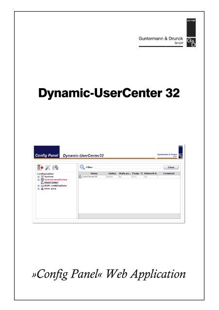
Dynamic-UserCenter 32<br />
»<strong>Config</strong> <strong>Panel</strong>« Web Application
About this manual<br />
This manual has been carefully compiled and examined to the state-of-the-art.<br />
G&D neither explicitly nor implicitly takes guarantee or responsibility for the quality,<br />
efficiency and marketability of the product when used for a certain purpose that<br />
differs from the scope of service covered by this manual.<br />
For damages which directly or indirectly result from the use of this manual as well<br />
as for incidental damages or consequential damages, G&D is liable only in cases of<br />
intent or gross negligence.<br />
Caveat Emptor<br />
G&D will not provide warranty for devices that:<br />
Are not used as intended.<br />
Are repaired or modified by unauthorized personnel.<br />
Show severe external damages that was not reported on the receipt of goods.<br />
Have been damaged by non G&D accessories.<br />
G&D will not be liable for any consequential damages that could occur from using<br />
the products.<br />
Proof of trademark<br />
All product and company names mentioned in this manual, and other documents<br />
you have received alongside your G&D product, are trademarks or registered trademarks<br />
of the holder of rights.<br />
Imprint<br />
© <strong>Guntermann</strong> & <strong>Drunck</strong> <strong>GmbH</strong> 2012. All rights reserved.<br />
Version 1.10 – 31/05/2012<br />
Version: 1.9.0<br />
<strong>Guntermann</strong> & <strong>Drunck</strong> <strong>GmbH</strong><br />
Dortm<strong>und</strong>er Str. 4a<br />
57234 Wilnsdorf<br />
Germany<br />
Phone +49 2739 8901-100<br />
Fax +49 2739 8901-120<br />
http://www.GDsys.de<br />
sales@GDsys.de<br />
i · Dynamic-UserCenter 32
Table of contents<br />
Contents<br />
Introduction ..................................................................................................... 1<br />
System requirements ......................................................................................... 2<br />
Supported web browsers .................................................................................... 2<br />
Java Runtime Environment ............................................................................... 2<br />
<strong>Config</strong>uring the network settings ..................................................................... 3<br />
Getting started .................................................................................................. 4<br />
Starting the web application ............................................................................... 4<br />
Security instructions of the web browser ............................................................. 4<br />
User login at the web application ....................................................................... 5<br />
Operating the web application ............................................................................ 6<br />
User interface ................................................................................................6<br />
Frequently used buttons .................................................................................7<br />
User logout ........................................................................................................ 7<br />
Selecting the default language of the web application .......................................... 8<br />
Choosing the hash algorithm to store passwords ................................................. 8<br />
Showing the version number of the web application ............................................ 8<br />
Administrating »Dynamic Ports« ........................................................................ 9<br />
<strong>Config</strong>uring »Dynamic Ports«.........................................................................9<br />
Changing the view modes of the »Dynamic Port« LEDs................................ 11<br />
Allowing or denying the direct connection of user modules ............................... 12<br />
Basic configuration of the web application ..................................................... 13<br />
Network settings .............................................................................................. 13<br />
<strong>Config</strong>uring the network settings .................................................................. 13<br />
<strong>Config</strong>uring the global network settings ........................................................ 14<br />
Increasing the reliability of network connections through link aggregation ..... 15<br />
Creating and administrating netfilter rules ........................................................ 16<br />
Creating new netfilter rules........................................................................... 17<br />
Editing existing netfilter rules ....................................................................... 18<br />
Deleting existing netfilter rules ..................................................................... 19<br />
Changing the order/priority of existing netfilter rules .................................... 19<br />
Creating an SSL certificate ............................................................................... 20<br />
Special features for complex KVM systems................................................... 20<br />
Creating a Certificate Authority.................................................................... 20<br />
Creating any certificate ................................................................................ 21<br />
Creating and signing the X509 certificate ...................................................... 22<br />
Creating a PEM file ..................................................................................... 23<br />
Updating the stored SSL certificate ................................................................... 24<br />
Backup and restore function ............................................................................. 25<br />
Firmware update ............................................................................................. 26<br />
Restoring the default settings ............................................................................ 26<br />
Dynamic-UserCenter 32 · ii
Contents<br />
Network functions of the devices .................................................................... 27<br />
NTP server ...................................................................................................... 27<br />
Time sync with an NTP server......................................................................27<br />
Setting time and date manually.....................................................................28<br />
Logging syslog messages .................................................................................. 29<br />
Locally logging the syslog messages ..............................................................29<br />
Sending syslog messages to a server ..............................................................30<br />
Viewing and saving local syslog messages .....................................................31<br />
User authentication with directory services ....................................................... 32<br />
Monitoring functions ...................................................................................... 34<br />
Viewing monitoring values ............................................................................... 35<br />
Listing values by applying monitoring sets ....................................................35<br />
Listing individual values of critical devices ....................................................35<br />
Disabling monitoring values ............................................................................. 36<br />
Advanced function regarding the administration of critical devices ................... 36<br />
Messages regarding critical statuses of devices ...............................................36<br />
Viewing the list of critical devices..................................................................37<br />
Marking messages from critical devices as read..............................................37<br />
Administrating monitor groups ......................................................................... 38<br />
Adding monitoring groups............................................................................38<br />
Changing name and/or comment of monitoring groups.................................39<br />
Assigning members to monitoring groups......................................................39<br />
Duplicating monitoring groups .....................................................................40<br />
Deleting monitoring groups ..........................................................................40<br />
Administrating monitoring sets ......................................................................... 41<br />
Adding monitoring sets ................................................................................41<br />
Changing name and/or comment of monitoring sets .....................................42<br />
Assigning members to monitoring sets ..........................................................42<br />
Selecting a monitoring set in the folder configuration.....................................43<br />
Duplicating monitoring sets ..........................................................................43<br />
Deleting monitoring sets...............................................................................44<br />
Device monitoring via SNMP ......................................................................... 45<br />
Practical use of the SNMP protocol .................................................................. 45<br />
<strong>Config</strong>uring the SNMP agent ........................................................................... 45<br />
<strong>Config</strong>uring SNMP traps .................................................................................. 47<br />
Logbook .......................................................................................................... 50<br />
The dialogue entries of the logbook ................................................................... 50<br />
The »Logbook configuration« window ..........................................................50<br />
Viewing a logbook entry in detail ..................................................................51<br />
Basic logbook functions .................................................................................... 51<br />
Creating a new logbook entry .......................................................................51<br />
Changing a logbook entry.............................................................................52<br />
Deleting a logbook entry...............................................................................53<br />
iii · Dynamic-UserCenter 32
Contents<br />
Advanced functions ......................................................................................... 53<br />
Printing logbook entries ............................................................................... 53<br />
Exporting logbook entries ............................................................................ 54<br />
Copying the logbook entries ......................................................................... 55<br />
Shared editing ................................................................................................. 56<br />
Users and Groups ........................................................................................... 57<br />
Efficient rights administration .......................................................................... 57<br />
The effective right ........................................................................................ 57<br />
Efficient user group administration............................................................... 58<br />
Administrating user accounts ........................................................................... 58<br />
Creating a new user account......................................................................... 59<br />
Renaming a user account ............................................................................. 60<br />
Changing the user account password ............................................................ 60<br />
Changing the user account rights .................................................................. 61<br />
Changing a user account’s group membership............................................... 61<br />
Enabling/Disabling a user account............................................................... 61<br />
Deleting a user account ................................................................................ 62<br />
Administrating user groups .............................................................................. 63<br />
Creating a new user group............................................................................ 63<br />
Renaming a user group ................................................................................ 63<br />
Changing the user group rights ..................................................................... 64<br />
Administrating user group members ............................................................. 64<br />
(De)activating a user group .......................................................................... 64<br />
Deleting a user group ................................................................................... 65<br />
System rights ................................................................................................... 65<br />
Rights for full access (Superuser) .................................................................. 65<br />
Changing the login right to the web application ............................................ 66<br />
Rights to change your own password............................................................ 66<br />
The »KVM combinations« folder .................................................................... 67<br />
Folder administration ...................................................................................... 67<br />
Creating new folders .................................................................................... 67<br />
Assigning a device to a folder ....................................................................... 68<br />
Deleting a device from a folder..................................................................... 68<br />
Renaming a folder ....................................................................................... 69<br />
Deleting a folder .......................................................................................... 69<br />
Advanced functions of the KVM system ......................................................... 70<br />
Temporarily (de)activating SNMP traps (Maintenance mode) ........................... 70<br />
(De)activating the maintenance mode........................................................... 70<br />
Viewing a list of devices in maintenance mode.............................................. 70<br />
Identifying a device by activating the Identification LED .................................... 71<br />
Saving and restoring the data of the KVM system ............................................. 71<br />
Overview of the monitoring values ................................................................. 72<br />
Dynamic-UserCenter 32 · iv
Introduction<br />
Introduction<br />
The <strong>Config</strong> <strong>Panel</strong> web application provides a graphical user interface to configure the<br />
KVM system.<br />
This application can be operated from any supported web browser (see page 2) and<br />
offers the following functions:<br />
Clearly arranged user interface<br />
Easy operation through the drag & drop function<br />
Monitoring of various system features<br />
Advanced network functions (netfilter, syslog, …)<br />
Backup and restore function<br />
1 · Dynamic-UserCenter 32
System requirements<br />
System requirements<br />
The <strong>Config</strong> <strong>Panel</strong> web application is an application that runs on the Java platform. It<br />
can be applied on a computer with installed Java Runtime Environment. Use one of the<br />
supported web browsers to run this application.<br />
IMPORTANT: Before operating the web application via web browser, connect the<br />
device on which the web application is operated to the local network (see installation<br />
guide).<br />
Now adjust the network settings as described on page 3.<br />
Supported web browsers<br />
The following web browsers support the web application:<br />
Internet Explorer 7<br />
Internet Explorer 8<br />
Internet Explorer 9<br />
Mozilla Firefox 11<br />
Java Runtime Environment<br />
The web application runs on Java Runtime Environment (JRE). Starting the web<br />
application requires the installation of version 6 (update 19).<br />
A free download of this version is available at the following website:<br />
http://java.sun.com/javase/downloads/<br />
NOTE: Mind the special instructions for running Java Runtime Environment on a 64bit<br />
browser for Windows:<br />
http://www.java.com/en/download/faq/java_win64bit.xml<br />
IMPORTANT: The OpenJDK open source implementation of the Java platform is not<br />
supported.<br />
Dynamic-UserCenter 32 · 2
<strong>Config</strong>uring the network settings<br />
<strong>Config</strong>uring the network settings<br />
To access the web application, the network settings of the device on which the web<br />
application is operated need to be configured.<br />
ADVICE: As an alternative to the steps described below, the network interfaces of a<br />
matrix switch can also be configured via the on-screen display of a user console.<br />
The following table lists the default settings of the Network A network interface:<br />
IP allocation: Static<br />
IP address: 192.168.0.1<br />
Subnet mask: 255.255.255.0<br />
Connection type: Auto<br />
NOTE: In the default, the Network B interface is deactivated.<br />
How to configure the network settings before integrating the device into the local<br />
network:<br />
1. Use a category 5 (or better) twisted pair cable to connect the network interface of<br />
any computer to the device’s Network A interface.<br />
2. Ensure that the IP address of the computer’s network interface is part of the subnet<br />
to which the device’s IP address belongs to.<br />
NOTE: Use the IP address 192.168.0.100, for example.<br />
3. Switch on the device.<br />
4. Start the computer’s web browser and enter 192.168.0.1 in the address bar.<br />
5. <strong>Config</strong>ure the network interface(s) and the global network settings as described in<br />
the paragraph Network settings on page 13 f.<br />
IMPORTANT: It is not possible to operate both network interfaces within one<br />
subnet!<br />
6. Remove the twisted pair cable connection between computer and device.<br />
7. Implement the device in the local network.<br />
3 · Dynamic-UserCenter 32
Getting started<br />
This chapter describes how to operate the web application.<br />
Starting the web application<br />
Getting started<br />
NOTE: The following chapters give a detailed overview of all functions and configuration<br />
settings.<br />
The web application can be operated on a computer with installed Java Runtime Environment.<br />
Use one of the supported web browsers to run this application.<br />
NOTE: Information regarding the system requirements of the web application are<br />
provided on page 2.<br />
How to start the web application:<br />
1. Enter the following address to call the web application:<br />
https://[ip address of the device]<br />
NOTE: If the web application is started via a “simple” http connection, a message<br />
informs the user that the connection can only be established via a secure https<br />
connection.<br />
After 10 seconds, you are automatically forwarded to a secure https connection.<br />
Security instructions of the web browser<br />
The device, on which the web application is operated, stores an SSL certificate that<br />
enables the user or the web browser to authenticate the opposite site.<br />
The certificate contains the following features:<br />
MD5 fingerprint:<br />
47:F0:FF:87:96:84:D7:C8:63:43:6D:77:26:64:59:CD<br />
SHA1 fingerprint:<br />
68:92:9F:83:04:CD:7A:12:ED:2B:FE:34:0F:DF:BA:4B:0C:EF:47:30<br />
IMPORTANT: Replace the certificate that is included in the defaults of the matrix<br />
switch with an individual certificate, which is related to the device. Information<br />
on how to create such a certificate is given on page 22.<br />
Dynamic-UserCenter 32 · 4
Getting started<br />
User login at the web application<br />
After you confirm the certificates, the login window opens.<br />
How to log in to the web application:<br />
1. Enter the following data in the login box:<br />
Username: Enter your username.<br />
Password: Enter your user account password.<br />
Select language: Select the language to be displayed on the user interface:<br />
2. Click the Login button.<br />
5 · Dynamic-UserCenter 32<br />
(Default): apply default setting<br />
German<br />
English<br />
IMPORTANT: Change the preset password of the administrator account immediately.<br />
Use the administrator account to log in to the web application and change the<br />
password (see page 60).<br />
These are the preset access data for the administrator account:<br />
Username: Admin<br />
Password: 4658
Operating the web application<br />
User interface<br />
The user interface of the web application consists of four main sections:<br />
<br />
<br />
Figure 1: User interface<br />
<br />
<br />
Getting started<br />
The different sectors of the user interface perform various tasks. The following table<br />
lists the intended use of each sector:<br />
Toolbar : The toolbar allows you to exit the active session and access the<br />
basic configuration of the web application. It is also possible to<br />
use the third icon for viewing and editing the assignment of the<br />
Dynamic Ports.<br />
Tree view : The tree view shows the setting options.<br />
Filter function : The filter function can be used to limit the elements that are<br />
displayed in the main view.<br />
Enter a part of the name of the searched element into the text<br />
field. Now, the main view only displays names that contain<br />
this particular text.<br />
Click Delete to cancel the filtering.<br />
Main view : After you selected an element in the tree view , the main<br />
view displays the superior elements.<br />
Dynamic-UserCenter 32 · 6
Getting started<br />
Frequently used buttons<br />
The user interface uses different buttons to carry out certain functions. The following<br />
table provides information on the names and functions of the buttons that are<br />
used in many interfaces.<br />
Reload: Reload window values from the system’s database. Changes that<br />
have been carried out by the user are overwritten.<br />
OK: Save your settings.<br />
Afterwards, the window closes.<br />
Apply: Save your settings.<br />
The window remains open.<br />
Cancel: Cancel your settings and close window.<br />
Print: Call print interface to select printer, page orientation and further<br />
settings.<br />
After the settings have been selected, the interface information<br />
(e.g., the cascade information) can be printed.<br />
Close: Close windows.<br />
User logout<br />
Use the Logout button to exit the current session within the web application.<br />
IMPORTANT: Always use the Logout function to exit your current session in order<br />
to protect the web application against unauthorised access.<br />
How to exit the current session within the web application:<br />
1. Click the Logout button (see figure on the right) to exit the current session<br />
within the web application.<br />
After your logout, the Login box is displayed.<br />
7 · Dynamic-UserCenter 32
Getting started<br />
Selecting the default language of the web application<br />
How to change the default language of the web application:<br />
1. Click the System entry in the tree view.<br />
2. Double-click on <strong>Config</strong>uration in the main view.<br />
3. Click the System tab.<br />
4. Use the Language entry to select the default language to be displayed to all users of<br />
the web application:<br />
German<br />
English<br />
5. Click OK to save the settings.<br />
Choosing the hash algorithm to store passwords<br />
By default, the database stores user passwords as MD5 hash values.<br />
If desired, you can change the hash algorithm to bcyrpt.<br />
NOTE: The bcyrpt hash algorithm is supported since firmware version 1.2.000.<br />
If required, update the firmware of one matrix switch before resetting a backup<br />
containing bcyrpt hash values.<br />
1. Click the System entry in the tree view.<br />
2. Double-click on <strong>Config</strong>uration in the main view.<br />
3. Click the System tab.<br />
4. Choose the algorithm from the Hash algorithm context menu:<br />
MD5<br />
bcrypt<br />
5. Click OK to save the settings.<br />
Showing the version number of the web application<br />
How to show the version number of the web application:<br />
1. Click on System > Information in the tree view.<br />
2. Double-click on General.<br />
3. Click on Close to close the window.<br />
Dynamic-UserCenter 32 · 8
Getting started<br />
Administrating »Dynamic Ports«<br />
In the default setting, the Dynamic Ports are divided into 8 groups. Each group lets you<br />
connect one target module and three matrix switches.<br />
The following screenshot shows the default port configuration:<br />
The following information are shown for each port:<br />
The computer icon highlights CPU ports.<br />
Connect a target module of the DVI-CPU series to these ports.<br />
The cluster icon highlights Cluster ports.<br />
Connect a matrix switch of the DVICenter series to these ports.<br />
Every assigned port belongs to a group. The group number<br />
is shown below the computer and cluster icons.<br />
The numbers result from the number of the group’s CPU port.<br />
<strong>Config</strong>uring »Dynamic Ports«<br />
The ports of the Dynamic-UserCenter 32 expansion can be grouped and assigned<br />
according to your personal preferences. Each group consists of a CPU port to which<br />
you can connect a target module. In addition, you can add at least two Cluster ports to<br />
the group. Connect the matrix switches that can access the target module to these<br />
ports.<br />
How to configure »Dynamic Ports«:<br />
1. Click the Dynamic Port icon (see figure on the right) in the tool bar of the<br />
web application.<br />
2. The configuration dialog shows the setting Graph below table (default) in the toolbar<br />
of the web application<br />
You can also choose between the options: Table only, Graph next to table or Graph only.<br />
3. If desired, click on Predefined configurations.<br />
Here, you can choose one of the frequently used configurations (1:3, 1:7 or 1:15),<br />
or you can reset the assignment of all ports (Unassigned).<br />
9 · Dynamic-UserCenter 32
Getting started<br />
4. You can also adjust the current port layout or one of the frequently used configurations<br />
as shown in the table below.<br />
NOTE: Select several ports by simultaneously pressing the left mouse key and<br />
Shift or Ctrl.<br />
NOTE: You can also carry out the actions via drag & drop.<br />
Carry out action in graph Carry out action in table<br />
TO CREATE A NEW PORT GROUP<br />
Right-click an unassigned port that<br />
you want to use as CPU port of the<br />
new group.<br />
Select New group from the context<br />
menu.<br />
5. Click Ok to save any changes.<br />
In the left column, click the CPU<br />
port you want to create for the new<br />
port group.<br />
Click .<br />
TO ASSIGN A CLUSTER PORT TO A PORT GROUP<br />
Right-click an unassigned port that<br />
you want to add as Cluster port of a<br />
group.<br />
Select Assign from the context<br />
menu.<br />
Select the CPU port in whose group<br />
you want to add the Cluster port.<br />
In the left column, click the Cluster<br />
port you want to add.<br />
In the right column, click the<br />
group name or a port of the group<br />
to which you want to add the Cluster<br />
port.<br />
Click .<br />
TO DELETE A CLUSTER PORT FROM A PORT GROUP<br />
Right-click the Cluster port you want<br />
to delete from the group.<br />
Select Delete from group from the<br />
context menu.<br />
TO DELETE A GROUP<br />
Warning: All ports of a port group are deleted.<br />
Right-click the CPU port whose<br />
group you want to delete.<br />
Select Delete group from the context<br />
menu.<br />
In the right column, click the Cluster<br />
port you want to delete from the<br />
group.<br />
Click .<br />
In the right column, click the CPU<br />
port whose group you want to<br />
delte.<br />
Click .<br />
NOTE: Click Print to print a detailed list of all ports.<br />
IMPORTANT: After you change the port assignment, the device reboots.<br />
6. Click the Logout icon (see figure on the right) to leave the active<br />
sessions of the web application.<br />
Dynamic-UserCenter 32 · 10
Getting started<br />
Changing the view modes of the »Dynamic Port« LEDs<br />
In the device’s default settings, the LEDs of the Dynamic Ports show the interface’s<br />
status.<br />
To facilitate the installation, you can switch the LEDs of the Dynamic Ports into Port<br />
mode. In Port mode, the Dynamic Ports to connect the matrix switches or the user<br />
modules are highlighted by green or yellow LEDs.<br />
How to enable the Port mode of Dynamic Ports:<br />
1. In the tree view, click UserCenter.<br />
2. Right-click the device, and select Dynamic Port LEDs > Show port type from the menu.<br />
3. Choose System to show the port modes of all ports, or choose the port group to<br />
which you want to limit the highlighting LEDs to.<br />
The LEDs of the Dynamic Ports highlight the current port mode:<br />
LED Port mode<br />
Yellow Connection of matrix switches<br />
Green Connection of target modules<br />
NOTE: If the port modes are active, the Identification LEDs on the device’s front<br />
and back side are blinking.<br />
How to enable the interface status of Dynamic Ports:<br />
1. In the tree view, click UserCenter.<br />
2. Right-click the device, and select Dynamic Port LEDs > Show status from the menu.<br />
3. Choose System to show the port modes of all ports, or choose the port group to<br />
which you want to limit the highlighting LEDs to.<br />
The LEDs of the Dynamic Ports now highlight the current status of the single ports<br />
(see Installation manual).<br />
11 · Dynamic-UserCenter 32
Getting started<br />
Allowing or denying the direct connection of user<br />
modules<br />
The device’s default settings allow you to connect user modules of the DVI-CON<br />
series instead of matrix switches to the Cluster ports.<br />
You can change this setting <strong>und</strong>er Direct consoles in the context menu.<br />
How to allow or deny the direct connection of user modules:<br />
1. In the tree view, click UserCenter.<br />
2. Right-click the device you want to configure and select <strong>Config</strong>uration from the context<br />
menu.<br />
3. Select one of the following options <strong>und</strong>er Direct consoles:<br />
Allowed: You are allowed to connect user modules of the DVI-CON<br />
series to the Cluster ports.<br />
4. Click Ok to close the window.<br />
It is possible to access a user module.<br />
Denied: You are denied to connect user modules of the DVI-CON<br />
series to the Cluster ports.<br />
Trying to access a user module triggers the message that a<br />
matrix switch could not be fo<strong>und</strong>.<br />
Dynamic-UserCenter 32 · 12
Basic configuration of the web application<br />
Basic configuration of the<br />
web application<br />
The tool symbol in the toolbar can be used to access the basic configuration of the<br />
web application.<br />
Here, you can change the network settings of the device on which the web application<br />
is operated as well as backup and restore these settings. Furthermore, a firmware<br />
update can be performed.<br />
Network settings<br />
The devices with integrated web application are provided with two network interfaces<br />
(Network A and Network B). These network interfaces enable you to integrate the<br />
device into up to two separate networks.<br />
IMPORTANT: Please mind the separate instructions regarding <strong>Config</strong>uring the<br />
network settings on page 3.<br />
<strong>Config</strong>uring the network settings<br />
<strong>Config</strong>ure the network settings to connect the device to a local network.<br />
How to configure the settings of a network interface:<br />
IMPORTANT: It is not possible to operate both network interfaces within one subnet.<br />
NOTE: According to RFC 3330, the Link Local address space 169.254.0.0/16 is<br />
reserved for the internal communication between devices. An IP address of this<br />
address space cannot be assigned.<br />
1. Click the tools symbol in the toolbar.<br />
2. Click the <strong>Config</strong>uration > Interfaces tabs.<br />
3. Use Interface A or Interface B paragraphs to enter the following data:<br />
Operational<br />
mode:<br />
13 · Dynamic-UserCenter 32<br />
Use the pull-down menu to select the operating mode of<br />
Interface A or Interface B:<br />
Off: switches off network interface.<br />
Static: uses static settings.<br />
DHCP: obtains the settings from a DHCP server.<br />
Link aggregation active: This interface was added to a group<br />
of network interfaces.<br />
Use the »Link aggregation« tab to configure the network interfaces.<br />
IP address: Only if the Static operating mode is selected: Enter the interface<br />
IP address.
Basic configuration of the web application<br />
Netmask: Only if the Static operating mode is selected: Enter the network<br />
netmask.<br />
Connection<br />
type:<br />
4. Click OK to save the data.<br />
<strong>Config</strong>uring the global network settings<br />
Even in complex networks the global network settings ensure that the web application<br />
is available from all sub networks.<br />
How to configure the global network settings:<br />
1. Click the tools symbol in the toolbar.<br />
2. Click the <strong>Config</strong>uration > Interfaces tabs.<br />
3. Enter the following data in the Global network settings section:<br />
Global preferences:<br />
4. Click OK to save your data.<br />
Select if the network interface and the remote station are to<br />
negotiate the connection type automatically (Auto) or if one<br />
of the available types is to be applied.<br />
Use the pull-down menu to select the operating mode:<br />
Static: uses static settings.<br />
DHCP: obtains the settings from a DHCP server.<br />
The following settings are automatically obtained in the DHCP operating<br />
mode. Inputs are not possible.<br />
Hostname: Enter the device hostname.<br />
Domain: Enter the domain the device is to belong to.<br />
Gateway: Enter the gateway IP address.<br />
DNS Server 1: Enter the DNS server IP address.<br />
DNS Server 2: Optionally, enter the IP address of another DNS server.<br />
Dynamic-UserCenter 32 · 14
Basic configuration of the web application<br />
Increasing the reliability of network connections through link<br />
aggregation<br />
In the default settings, you can use both network interfaces at the same time to<br />
access the web application from two different network segments, for example.<br />
To increase the reliability, the network interfaces can be grouped through link aggregation.<br />
Only one interface is active within the group. Another interface only becomes<br />
active if the active interface fails.<br />
We provide two different modes to monitor the interfaces:<br />
MII mode: The carrier status of the network interface is monitored through the<br />
Media Independent Interface. This mode only checks the function of the network interface.<br />
ARP mode: The address resolution protocol sends requests to an ARP target within the<br />
network. The answer of the ARP target confirms both the functionality of the network<br />
interface and the proper network connection to the ARP target.<br />
If the ARP target is connected to the network but is temporarily offline, requests<br />
cannot be answered. Define multiple ARP targets to receive an answer from at least<br />
one target if an ARP target fails.<br />
NOTE: MII and ARP mode cannot be combined.<br />
How to configure the settings of grouped network interfaces:<br />
NOTE: According to RFC 3330, the Link Local address space 169.254.0.0/16 is<br />
reserved for the internal communication between devices. An IP address of this<br />
addres space cannot be assigned.<br />
1. Click the tools symbol in the toolbar.<br />
2. Click the Network > Interfaces > Link aggregation tab.<br />
3. Enter the following data into the Network paragraph:<br />
Name: Enter a name for the group of network interfaces.<br />
Operational<br />
mode:<br />
15 · Dynamic-UserCenter 32<br />
Choose the operational mode for the grouped network interfaces:<br />
Off: disables link aggregation.<br />
Use the »Interfaces« tab to configure the network interfaces.<br />
Static: A static IP address is assigned.<br />
DHCP: obtain IP address from a DHCP server.<br />
IP address: Enter the IP address of the interface (only if you have selected<br />
the Static operational mode).<br />
Netmask: Enter the netmask of the network (only if you have selected<br />
the Static operational mode).
4. Enter the following data in the Parameter paragraph:<br />
5. Click OK to save your settings.<br />
Basic configuration of the web application<br />
Link monitoring: Choose if you want the MII or ARP mode (description see<br />
below) to be used to monitor the interface.<br />
MII down delay: Time delay in milliseconds before a failed network interface<br />
is disabled.<br />
The value must be a multiple of 100 ms (the MII link monitoring<br />
frequency).<br />
MII up delay: Time delay in milliseconds before a reset network interface is<br />
enabled.<br />
The value must be a multiple of 100 ms (the MII link monitoring<br />
frequency).<br />
ARP interval: Enter the interval (100 to 10,000 milliseconds) according to<br />
which the incoming ARP packets of the network interfaces<br />
are to be checked.<br />
ARP validate: The validation ensures that the ARP packet for a particular<br />
network interface is generated by one of the listed ARP targets.<br />
Choose if or what incoming ARP packets are to be validated:<br />
None: ARP packets are not validated (default).<br />
Active: Only the ARP packets of the active network interface<br />
are validated.<br />
Backup: Only the ARP packets of the inactive network<br />
interface are validated.<br />
All: The ARP packets of all network interfaces within the<br />
group are validated.<br />
ARP target: The table lists all configured ARP targets.<br />
Use the New, Edit, and Delete buttons to administrate the ARP<br />
targets.<br />
Creating and administrating netfilter rules<br />
In the default settings of the devices, all network computers have access to the<br />
<strong>Config</strong> <strong>Panel</strong> web application (open system access).<br />
NOTE: The open system access enables unrestricted connections via the following<br />
ports: 80/TCP (HTTP), 443/TCP (HTTPS) and 161/UDP (SNMP).<br />
If you create a netfilter rule, the open system access is deactivated and all incoming<br />
data packets are compared to the netfilter rules. The list of the netfilter rules is processed<br />
according to the stored order. As soon as a rule applies, it is carried out and<br />
the following rules are ignored.<br />
Dynamic-UserCenter 32 · 16
Basic configuration of the web application<br />
Creating new netfilter rules<br />
How to create new netfilter rules:<br />
1. Click the tools symbol in the toolbar.<br />
2. Click the Network > Interfaces > Netfilter tabs.<br />
3. Enter the data described below.<br />
Interface: Use the pull-down menu to select on which network interfaces<br />
the data packets are to be trapped and manipulated:<br />
17 · Dynamic-UserCenter 32<br />
All<br />
Interface A<br />
Interface B<br />
[Name of a group of network interfaces]<br />
Option: Use the pull-down menu to select how the rule’s sender<br />
information are to be interpreted:<br />
Normal: The rule applies for data packets whose sender<br />
information does comply with the indicated IP address or<br />
MAC address.<br />
Inverted: The rule applies for data packets whose sender<br />
information does not comply with the indicated IP address<br />
or MAC address.<br />
IP address/<br />
Netmask:<br />
Enter the data packet IP address or use the Netmask entry to<br />
enter the address space of the IP addresses.<br />
Examples:<br />
192.168.150.187: for IP address 192.168.150.187<br />
192.168.150.0/24: IP addresses of section 192.168.150.x<br />
192.168.0.0/16: IP addresses of section 192.168.x.x<br />
192.0.0.0/8: IP addresses of section 192.x.x.x<br />
0.0.0.0/0: all IP addresses<br />
NOTE: The IP address and/or a MAC address can be specified within a rule.<br />
MAC address: Enter the MAC address to be considered in this filter rule.<br />
NOTE: The IP address and/or a MAC address can be specified within a rule.<br />
Filter rule: Drop: Data packets whose sender information comply with<br />
the IP address or MAC address are not processed.<br />
Accept: Data packets whose sender information comply<br />
with the IP address or MAC address are processed.
4. Click Add to save the data in a new filter rule.<br />
Basic configuration of the web application<br />
The new filter rule is added to the end of the list of the existing filter rules.<br />
5. Click OK to close the window.<br />
Editing existing netfilter rules<br />
How to edit an existing netfilter rule:<br />
1. Click the tools symbol in the toolbar.<br />
2. Click the Network > Interfaces > Netfilter tabs.<br />
3. Mark the rule to be changed in the list of the existing netfilter rules.<br />
4. The current rule settings are displayed in the upper part of the window. Check<br />
and change the data described on the following page.<br />
Interface: Use the pull-down menu to select on which network interfaces<br />
the data packets are to be trapped and manipulated:<br />
All<br />
Interface A<br />
Interface B<br />
Option: Use the pull-down menu to select how the rule’s sender<br />
information are to be interpreted:<br />
Normal: The rule applies for data packets whose sender<br />
information does comply with the indicated IP address or<br />
MAC address.<br />
Inverted: The rule applies for data packets whose sender<br />
information does not comply with the indicated IP address<br />
or MAC address.<br />
IP address/<br />
Netmask:<br />
Enter the data packet IP address or – using the Netmask entry<br />
– the address space of the IP addresses.<br />
Examples:<br />
192.168.150.187: for the IP address 192.168.150.187<br />
192.168.150.0/24: IP addresses of section 192.168.150.x<br />
192.168.0.0/16: IP addresses of section 192.168.x.x<br />
192.0.0.0/8: IP addresses of section 192.x.x.x<br />
0.0.0.0/0: all IP addresses<br />
The IP address and/or a MAC address can be indicated within a rule.<br />
MAC address: Enter the MAC address to be considered in this filter rule.<br />
The IP address and/or a MAC address can be indicated within a rule.<br />
Dynamic-UserCenter 32 · 18
Basic configuration of the web application<br />
Filter rule: Drop: Data packets whose sender information comply with<br />
the IP address or MAC address are not processed.<br />
Accept: Data packets whose sender information comply<br />
with the IP address or MAC address are processed.<br />
5. Click Change to save the changed data.<br />
6. Click OK to close the window.<br />
Deleting existing netfilter rules<br />
How to delete existing netfilter rules:<br />
1. Click the tools symbol in the toolbar.<br />
2. Click the Network > Interfaces > Netfilter tabs.<br />
3. Mark the rule to be deleted in the list of the existing netfilter rules.<br />
4. Click Remove.<br />
5. Confirm the confirmation prompt by pressing Yes or cancel the process by clicking<br />
No.<br />
6. Click OK to close the window.<br />
Changing the order/priority of existing netfilter rules<br />
The netfilter rules are processed in the order they are stored. If a rule does apply, the<br />
respective action is carried out and all following rules are ignored.<br />
IMPORTANT: Please mind the order or priority of the single rules, especially when<br />
adding new rules.<br />
How to change the order/priority of existing netfilter rules:<br />
1. Click the tools symbol in the toolbar.<br />
2. Click the Network > Interfaces > Netfilter tabs.<br />
3. Mark the rule whose order/priority is to be changed in the list of the existing netfilter<br />
rules.<br />
4. Click the button (arrow up) to increase the priority or the button (arrow down)<br />
to decrease the priority.<br />
5. Click OK to close the window.<br />
19 · Dynamic-UserCenter 32
Creating an SSL certificate<br />
Basic configuration of the web application<br />
Use the free implementation of the SSL/TLS protocol OpenSSL to create an SSL<br />
certificate.<br />
The following websites provide detailed information about operating OpenSSL:<br />
OpenSSL project: http://www.openssl.org/<br />
Win32 OpenSSL: http://www.slproweb.com/products/Win32OpenSSL.html<br />
OpenSSL manual: http://www.absolute-cool.net/dokus/ssl/openssl/<br />
IMPORTANT: Creating an X509 certificate requires the software OpenSSL. If necessary,<br />
follow the instructions on the websites mentioned above to install the software.<br />
The following pages give information on creating an X509 certificate.<br />
Special features for complex KVM systems<br />
If you want different devices to communicate within a KVM system, use the identical<br />
Certificate Authority (see page 20) to create certificates for those devices.<br />
NOTE: The identical PEM file (see page 23) can also be used for all devices. In this<br />
case, all certificate features are identical.<br />
Creating a Certificate Authority<br />
A Certificate Authority enables the owner to create digital certificates (e. g. for the<br />
matrix switch DVICenter).<br />
How to create a key for the Certificate Authority:<br />
IMPORTANT: The following steps describe how to create keys that are not coded.<br />
If necessary, read the OpenSSL manual to learn how to create a coded key.<br />
1. Enter the following command into the command prompt and press Enter:<br />
openssl genrsa -out ca.key 2048<br />
2. OpenSSL creates the key and stores it in a file named ca.key.<br />
Dynamic-UserCenter 32 · 20
Basic configuration of the web application<br />
How to create the Certificate Authority:<br />
1. Enter the following command into the command prompt and press Enter:<br />
openssl req -new -x509 -days 365 -key ca.key -out ca.crt<br />
2. Now, OpenSSL queries the data to be integrated into the certificate.<br />
The following table shows the different fields and an exemplary entry:<br />
Field Example<br />
Country Name (2 letter code) DE<br />
State or Province Name NRW<br />
Locality Name (e.g., city) Wilnsdorf<br />
Organization Name (e.g., company) <strong>Guntermann</strong> & <strong>Drunck</strong> <strong>GmbH</strong><br />
Organizational Unit Name<br />
(e.g., section)<br />
Common Name (e.g., YOUR name) <strong>Guntermann</strong> & <strong>Drunck</strong> <strong>GmbH</strong><br />
Email Address<br />
Enter the data you want to state and confirm each entry by pressing Enter.<br />
3. OpenSSL creates the key and stores it in a file named ca.crt.<br />
Creating any certificate<br />
How to create a key for the certificate to be created:<br />
IMPORTANT: The following steps describe how to create keys that are not coded.<br />
If necessary, read the OpenSSL manual to learn how to create a coded key.<br />
1. Enter the following command into the command prompt and press Enter:<br />
openssl genrsa -out server.key 2048<br />
2. OpenSSL creates the key and stores it in a file named server.key<br />
21 · Dynamic-UserCenter 32
How to create the certificate:<br />
Basic configuration of the web application<br />
1. Enter the following command into the command prompt and press Enter:<br />
openssl req -new -key server.key -out server.csr<br />
2. Now, OpenSSL queries the data to be integrated into the certificate.<br />
The following table shows the different fields and an exemplary entry:<br />
Field Example<br />
Country Name (2 letter code) DE<br />
State or Province Name NRW<br />
Locality Name (e.g., city) Wilnsdorf<br />
Organization Name (e.g., company) <strong>Guntermann</strong> & <strong>Drunck</strong> <strong>GmbH</strong><br />
Organizational Unit Name<br />
(e.g., section)<br />
Common Name (e.g., YOUR name) 192.168.0.10<br />
Email Address<br />
IMPORTANT: Enter the IP address of the device on which the certificate is to be<br />
installed into the row Common Name.<br />
Enter the data you want to state, and confirm each entry by pressing Enter.<br />
3. If desired, the Challenge Password can be defined. This password is needed if you<br />
have lost the secret key and the certificate needs to be recalled.<br />
4. Now, the certificate is created and stored in a file named server.csr.<br />
Creating and signing the X509 certificate<br />
1. Enter the following command into the command prompt and press Enter:<br />
openssl x509 -req -days 365 -in server.csr -CA ca.crt -CAkey ca.key -set_serial 01 -out<br />
server.crt<br />
Dynamic-UserCenter 32 · 22
Basic configuration of the web application<br />
2. Now, OpenSSL queries the data to be integrated into the certificate.<br />
The following table shows the different fields and an exemplary entry:<br />
Field Example<br />
Country Name (2 letter code) DE<br />
State or Province Name NRW<br />
Locality Name (e.g., city) Wilnsdorf<br />
Organization Name (e.g., company) <strong>Guntermann</strong> & <strong>Drunck</strong> <strong>GmbH</strong><br />
Organizational Unit Name<br />
(e.g., section)<br />
Common Name (e.g., YOUR name) <strong>Guntermann</strong> & <strong>Drunck</strong> <strong>GmbH</strong><br />
Email Address<br />
Enter the data you want to state and confirm each entry by pressing Enter.<br />
3. OpenSSL creates the certificate and stores it in a file named server.crt.<br />
Creating a PEM file<br />
1. Enter the following command(s) into the prompt and press Enter:<br />
a. Linux<br />
cat server.crt > gdcd.pem<br />
cat server.key >> gdcd.pem<br />
cat ca.crt >> gdcd.pem<br />
b. Windows<br />
copy server.crt + server.key + ca.crt gdcd.pem<br />
2. The gdcd.pem file is created during the copying. It contains the created certificate<br />
and its key as well as the Certificate Authority.<br />
23 · Dynamic-UserCenter 32
Updating the stored SSL certificate<br />
Basic configuration of the web application<br />
An SSL-secured connection connects the web browser to the web application. The<br />
device on which the web application is operated stores an SSL certificate, which<br />
enables the user or the web browser to authenticate the opposite site.<br />
If the device’s IP address differs from the IP address given in the certificate, the web<br />
browser sends a message. It is therefore recommended to import an individual certificate<br />
in order to ensure that the device IP address complies with the IP address<br />
given in the certificate.<br />
The certificate given by the certificate authority or one that is created by the user can<br />
be imported (e.g. with the open source toolkit OpenSSL).<br />
NOTE: The required .pem file contains the following three components:<br />
server certificate<br />
private server key<br />
certificate of the certification authority<br />
If these three components are available separately, enter them successively to the<br />
Clear text entry before updating the certificate stored in the device.<br />
How to update the SSL certificate stored in the device:<br />
1. Click the tools symbol in the toolbar.<br />
2. Click the <strong>Config</strong>uration > Certificate tabs.<br />
3. Copy the certificate’s content or import the .pem file in the interface<br />
Clear text: Copy the clear text of the server certificate, the private server<br />
key, and the certificate of the certification authority to this<br />
text field.<br />
ADVICE: If the certificates and the private key are provided in a .pem file,<br />
use the Import certificate from file... function described below.<br />
Import certificate<br />
from file...<br />
4. Click Update now.<br />
5. Click OK to leave the interface.<br />
Click this interface if the certificates and the key are provided in<br />
a .pem file. Select the .pem file in the file window.<br />
The clear text of the feature key is automatically displayed in<br />
the Clear text entry.<br />
Dynamic-UserCenter 32 · 24
Basic configuration of the web application<br />
Backup and restore function<br />
The network settings of the device on which the web application is operated can be<br />
stored using the backup function. The restore function enables the user to restore the<br />
saved data.<br />
NOTE: The chapter Saving and restoring the data of the KVM system on page 71 provides<br />
information regarding saving and restoring the system settings.<br />
How to backup the network settings:<br />
1. Click the tools symbol in the toolbar.<br />
2. Click the Tools > Backup/Restore tabs.<br />
3. Click the Backup button and, if desired, enter a Comment and a Password to secure<br />
the backup file.<br />
4. Click OK.<br />
5. Use the date window to define the location and the File name of the backup file.<br />
6. Click Save.<br />
7. Click OK to close the window.<br />
How to restore the network settings:<br />
1. Click the tools symbol in the toolbar.<br />
2. Click the Tools > Backup/Restore tabs.<br />
3. Enter the storage location and the name of the backup file into the Path entry.<br />
ADVICE: Use the file button to select the storage location and the name of the<br />
backup file in the file interface.<br />
4. Click on Check file to check the validity of the backup file.<br />
IMPORTANT: Use the information provided in the Date and Comment entries to<br />
check if you selected the correct backup file.<br />
5. Click on Restore.<br />
6. Click OK to leave the interface.<br />
25 · Dynamic-UserCenter 32
Firmware update<br />
Basic configuration of the web application<br />
The firmware of each device can be easily updated via the web application.<br />
IMPORTANT: This function only updates the firmware of the device on which the<br />
web application has been started!<br />
How to update the firmware:<br />
1. Open the web application of the device whose firmware you want to update.<br />
2. Click the tools symbol in the toolbar.<br />
3. Click the Tools > Firmware update tabs.<br />
4. Enter the storage location and the name of the backup file into the Path entry.<br />
IMPORTANT: Use the information provided in the Device and Comment entries to<br />
check if you selected the correct device file.<br />
ADVICE: Use the file dialog to select the location and the name of the update file.<br />
5. Click on Update now.<br />
6. Click OK to leave the interface.<br />
Restoring the default settings<br />
This function enables the user to restore the default settings of the device on which<br />
the web application is operated.<br />
How to restore the default settings:<br />
IMPORTANT: All settings are reset.<br />
1. Click the tools symbol in the toolbar.<br />
2. Click the Tools > System defaults tabs.<br />
IMPORTANT: Use the information provided in the Date and Comment entries to<br />
check if you have selected the correct backup file.<br />
3. Enable the option Delete dynamic ports to reset the configuration of the Dynamic<br />
Ports.<br />
4. Disable the Delete IP addresses option to maintain the configuration of the network<br />
interfaces.<br />
5. Click on System Defaults to reset the current configuration.<br />
6. Click OK to leave the interface.<br />
Dynamic-UserCenter 32 · 26
Network functions of the devices<br />
Network functions of the devices<br />
The different devices within the KVM system (e.g. KVM extenders and KVM matrix<br />
switches) provide separate network functions.<br />
The following function can be configured for each device within the KVM system:<br />
Authentication against directory services (LDAP, Active Directory, RADIUS,<br />
TACACS+)<br />
Time synchronisation via NTP server<br />
Forwarding of log messages to syslog servers<br />
Monitoring and control of computers and network devices via Simple Network Management<br />
Protocol (see page 49 ff.)<br />
NTP server<br />
The device’s time and date settings can either adjust be adjusted manually or automatically<br />
by synchronizing the settings with an NTP server (Network Time Protocol).<br />
Time sync with an NTP server<br />
How to change the NTP time sync settings:<br />
1. Use the tree view to click on UserCenter.<br />
2. Right-click the device to be configured. Now click the <strong>Config</strong>uration entry in the<br />
context menu.<br />
3. Click the Network tab.<br />
4. Click the NTP server tab and enter the following data:<br />
NTP time sync: Select the respective entry from the pull-down menu to<br />
(de)activate the time sync:<br />
Disabled<br />
Enabled<br />
NTP server 1: Enter the IP address of a time server.<br />
NTP server 2: Optionally enter the IP address of a second time server.<br />
Time zone: Use the pull-down menu to select the time zone of your<br />
location.<br />
5. Click OK to close the window.<br />
27 · Dynamic-UserCenter 32
Setting time and date manually<br />
Network functions of the devices<br />
How to manually set the time and date of the KVM matrix system:<br />
1. Use the tree view to click on UserCenter.<br />
2. Right-click the device to be configured. Now click the <strong>Config</strong>uration entry in the<br />
context menu.<br />
3. Click the Network > NTP server tabs.<br />
4. If necessary, disable the NTP time sync option. Otherwise, you might not be able to<br />
set time and date manually.<br />
5. Use the Time entry to enter the current time (hh:mm:ss).<br />
6. Use the Date entry to enter the current time (DD.MM.YYYY).<br />
ADVICE: Click on Accept local date to accept the current system date of the computer<br />
on which the <strong>Config</strong> <strong>Panel</strong> web application has been started.<br />
7. Click OK.<br />
Dynamic-UserCenter 32 · 28
Network functions of the devices<br />
Logging syslog messages<br />
The syslog protocol is used to transmit log messages in networks. The log messages<br />
are transmitted to a syslog server that logs the log messages of many devices in the<br />
computer network.<br />
Among other things, eight different severity codes have been defined to classify the<br />
log messages:<br />
0: Emergency<br />
1: Alert<br />
2: Critical<br />
The web application enables you to configure whether the syslog messages are to be<br />
locally logged or sent to up to two syslog servers.<br />
Locally logging the syslog messages<br />
How to locally log the syslog messages:<br />
1. Use the tree view to click on UserCenter.<br />
2. Right-click the device to be configured. Now click the <strong>Config</strong>uration entry in the<br />
context menu.<br />
3. Click the Network tab.<br />
4. Click the Syslog tab and enter the following data in the Syslog local section:<br />
5. Click OK to close the window.<br />
29 · Dynamic-UserCenter 32<br />
3: Error<br />
4: Warning<br />
5: Note<br />
6: Info<br />
7: Debug<br />
Syslog server: Select the respective entry from the pull-down menu to define<br />
whether syslog messages are to be sent to a server:<br />
Disabled<br />
Enabled<br />
Log Level: Use the pull-down menu to select from which severity code<br />
on a log message is to be logged.<br />
The selected severity code and all lower severity codes are<br />
logged.<br />
If you selected the severity code 2 - Critical, messages for this code as well<br />
as for the severity codes 1 - Alert and 0 - Emergency are logged.
Sending syslog messages to a server<br />
How to send syslog messages to a server:<br />
1. Use the tree view to click on UserCenter.<br />
Network functions of the devices<br />
2. Right-click the device to be configured. Now click the <strong>Config</strong>uration entry in the<br />
context menu.<br />
3. Click the Network tab.<br />
4. Click the Syslog tab and enter the following data in the Syslog server 1 or<br />
Syslog server 2 section:<br />
Syslog server: Select the respective entry from the pull-down menu to<br />
define whether syslog messages are to be sent to a server<br />
or not:<br />
Disabled<br />
Enabled<br />
Log Level: Use the pull-down menu to select from which severity<br />
code on a log message is to be logged.<br />
The selected severity code and all lower severity codes<br />
are logged.<br />
If you select severity code 2 - Critical, messages for this code and for the<br />
severity codes 1 - Alert and 0 - Emergency are logged.<br />
IP address/<br />
DNS name:<br />
5. Click OK to close the window.<br />
Enter the IP address or the server name to which the syslog<br />
messages are to be sent.<br />
Port: Enter the port – usually 514 – on which the server receives<br />
the incoming messages.<br />
Protocol: Select the protocol – usually UDP – on which the server<br />
receives the incoming messages:<br />
TCP<br />
UDP<br />
Dynamic-UserCenter 32 · 30
Network functions of the devices<br />
Viewing and saving local syslog messages<br />
If the function to log the local syslog messages is activated, these syslog messages<br />
can be viewed and, if necessary, stored in the information window.<br />
How to view and store the local syslog messages:<br />
1. Click on System > Information in the tree view.<br />
2. Right-click the device to be configured. Now click the <strong>Config</strong>uration entry in the<br />
context menu.<br />
3. Double-click on Syslog in the main view.<br />
4. Click the Fetch syslogs tab.<br />
The matrix switch calls the local syslog messages, which are now displayed in the<br />
text field.<br />
ADVICE: If necessary, click Save to save these messages in a text file. The opening<br />
file window enables you to select the location and a file name.<br />
Afterwards, click Save.<br />
5. Click OK to close the window.<br />
31 · Dynamic-UserCenter 32
User authentication with directory services<br />
Network functions of the devices<br />
In in-house networks, the user accounts of different users are often administrated by<br />
a directory service. The device can access such a directory service and authenticate<br />
users against the directory service.<br />
NOTE: If the Admin user account cannot be authenticated by the directory service,<br />
the user account is authenticated by the device’s data base.<br />
The directory service is exclusively used to authenticate a user. The user rights are<br />
assigned within a database of the KVM system. The following paragraphs describe the<br />
different scenarios:<br />
The user account exists within the directory service and the KVM system<br />
The user can log in with the password stored in the directory service. After the<br />
login, the user is assigned with the rights of the correspondent account in the<br />
KVM system.<br />
NOTE: The password which the user used to log in, is taken over into the database<br />
of the KVM system.<br />
The user account exists within the directory service, but not within the KVM system<br />
A user that has been successfully authenticated against the directory service, but<br />
does not have an account of the same name within the database of the KVM system,<br />
is assigned with the rights of the RemoteAuth user.<br />
If required, change the rights of this particular user account to set the rights for<br />
users without a user account.<br />
ADVICE: Deactivate the RemoteAuth user to prevent users without user accounts<br />
to log in to the KVM system.<br />
The user account exists within the KVM system, but not within the directory service<br />
If the directory service is available, it reports that the user account does not exist.<br />
The access to the KVM system is denied to the user.<br />
If the server is not available, but the fallback system is active (see below), the user<br />
can log in with the password that is stored within the KVM system.<br />
IMPORTANT: Mind the following safety instructions to prevent a locked or deactivated<br />
user from logging in to the system in case the connection to the directory<br />
service fails:<br />
If a user account is deactivated or deleted in the directory service, this action<br />
can also be carried out within the user database of the KVM system.<br />
Only activate the fallback system in reasonable exceptional cases.<br />
Dynamic-UserCenter 32 · 32
Network functions of the devices<br />
How to configure the user account authentication:<br />
NOTE: If no directory service is applied, the user accounts are administered by the<br />
device.<br />
1. Use the tree view to click on UserCenter.<br />
2. Right-click the device to be configured. Now, click the <strong>Config</strong>uration entry in the<br />
context menu.<br />
3. Click the Network > Authentication tabs and enter the following data:<br />
Auth. Server: Select the Local option if the user administration is to be carried<br />
out by the KVM system.<br />
4. Click OK to close the window.<br />
33 · Dynamic-UserCenter 32<br />
If a particular directory service is to be applied, select the<br />
respective entry from the pull-down menu:<br />
LDAP<br />
Active Directory<br />
Radius<br />
TACACS+<br />
ADVICE: After the directory service has been selected, collect the settings of<br />
the directory service server in the Server settings.<br />
Fallback: Activate this option if the local user administration of the<br />
KVM system is to be applied in case the directory service is<br />
temporarily not available.<br />
IMPORTANT: Mind the following safety instructions to prevent a locked or<br />
deactivated user from logging in to the system in case the connection to<br />
the directory service fails:<br />
If a user account is disabled or deleted in the directory service, this action<br />
can also be carried out within the user database of the KVM system.<br />
Only activate the fallback system in reasonable exceptional cases.
Monitoring functions<br />
Monitoring functions<br />
The current monitoring values of all devices within the KVM system can be viewed in<br />
the device-specific branches (e.g. KVM matrix systems) as well as in the KVM Combinations<br />
and Critical Devices branches of the tree view.<br />
The various information regarding a device can either be displayed in individual values<br />
or in monitoring groups, which are sorted according to topic. The following<br />
exemplary figure shows the Status values and three different monitoring groups:<br />
Figure 2: Detailed view of an exemplary monitoring table<br />
Individual values (the Status value in the figure above) immediately show if the status is<br />
correct (green) or deviating from the normal operating value (red). The text in the column<br />
also provides information about the current status.<br />
Monitoring groups allow you to group various individual values. The column of a<br />
monitoring group shows if all values are within range (OK) or if at least one value is<br />
deviating from the normal operating values (Error).<br />
Clicking the arrow in the column opens a separate window, which displays the individual<br />
values of the group.<br />
Dynamic-UserCenter 32 · 34
Monitoring functions<br />
Viewing monitoring values<br />
NOTE: An overview of the possible monitoring values of all different device types<br />
is given on page 72 ff.<br />
By applying different monitoring sets, the monitoring values are displayed in the different<br />
branches of the tree view.<br />
Several branches (e.g. Critical devices) provide another view to enable the user to<br />
detect critical monitoring values as fast as possible.<br />
Listing values by applying monitoring sets<br />
A monitoring set defines which individual values and groups are to be displayed.<br />
The column, which shows the individual values, enables you to read the status and<br />
check whether it is deviating from the normal operating values.<br />
Monitoring groups allow you to group various individual values. The column of a<br />
monitoring group shows if all values are within range (OK) or if at least one value is<br />
deviating from the normal operating values (Error).<br />
Clicking the arrow in the column opens a window, which contains detailed information<br />
regarding the individual values of the group.<br />
ADVICE: The following pages of this chapter provide detailed information regarding<br />
monitoring groups and monitoring sets.<br />
Listing individual values of critical devices<br />
If a device shows a value that deviates from the normal operating values, the device<br />
is additionally listed in the Critical devices branch. This branch displays all deviating<br />
(red) values in tabular form. This way, deviating values can be detected as fast as<br />
possible.<br />
NOTE: To be able to find deviant values as fast as possible, monitoring sets are not<br />
applied here.<br />
35 · Dynamic-UserCenter 32
Disabling monitoring values<br />
Monitoring functions<br />
Any monitoring value can be disabled. After disabling, the monitoring values are no<br />
longer shown in the web application.<br />
IMPORTANT: Critical values are no longer shown for any disabled values.<br />
How to enable/disable the monitoring values:<br />
1. Use the tree view to click on UserCenter.<br />
2. Right-click the device to be configured. Now, click the <strong>Config</strong>uration entry in the<br />
context menu.<br />
3. Click the Monitoring tab.<br />
Two tables list the monitoring values of the KVM system:<br />
Enabled: lists all active monitoring values.<br />
Disabled: lists all inactive monitoring values.<br />
To give you a faster overview, the values are grouped in both columns.<br />
4. Mark the monitoring values to be enabled/disabled.<br />
5. Click the button (right arrow key) to disable the monitoring value or<br />
(left arrow key) for enabling.<br />
6. Click OK to save your settings.<br />
Advanced function regarding the administration of<br />
critical devices<br />
The Critical Devices branch lists the devices that show at least one value that exceeds<br />
the normal operating values.<br />
NOTE: A sub-branch is displayed for each device class in the KVM system (e. g.<br />
KVM matrix systems).<br />
Messages regarding critical statuses of devices<br />
If one value exceeds the normal operating values, the branch is marked red. A blinking<br />
message <strong>und</strong>er the main view points to this condition.<br />
ADVICE: If the blinking message appears on your screen, press Ctrl+Space to open<br />
the Critical devices branch.<br />
Click on the blinking message to show the list of the deviating values in a separate<br />
window.<br />
Dynamic-UserCenter 32 · 36
Monitoring functions<br />
Viewing the list of critical devices<br />
How to view the list of critical devices:<br />
1. Click on the System monitoring > Critical Devices folders in the tree view.<br />
The main view lists all affected devices. The critical values are displayed in the table.<br />
ADVICE: Click a sub-branch of the folder in order to only list the devices of a<br />
particular device class.<br />
Marking messages from critical devices as read<br />
Many messages require immediate actions from the administrator. Other messages<br />
(e.g. the break-down of the red<strong>und</strong>ant power supply), however, point to possibly<br />
uncritical conditions.<br />
In such a case, all peculiar values of a device can be marked as read, which causes<br />
the following:<br />
A device whose deviating values have been marked as read shows no blinking status<br />
bar.<br />
The cells, info dialogues and monitoring windows of all “read” devices are highlighted<br />
in yellow.<br />
If a monitoring group contains critical values, which have been marked as read,<br />
the column displays Error. In addition, the cell is highlighted in yellow.<br />
NOTE: The system only highlights values that have been deviating from the normal<br />
operating values at the time the function has been executed. The web application<br />
shows if another monitoring value of such a device deviates from the normal operating<br />
values.<br />
How to mark the Monitoring messages of a device as read:<br />
1. Click on the System monitoring > Critical Devices folders in the tree view.<br />
2. Right-click the desired device. Now click the Acknowledge entry of the context menu.<br />
37 · Dynamic-UserCenter 32
Administrating monitor groups<br />
Monitoring functions<br />
IMPORTANT: Any recently created monitoring groups are only available in the<br />
branch in which they were created.<br />
If a monitoring group was created in a device-specific branch, it is no longer available<br />
in the KVM combinations branch.<br />
The <strong>Config</strong> <strong>Panel</strong> web application already provides several default monitoring<br />
groups. Those groups can neither be edited nor deleted, but they can be duplicated<br />
and individually adjusted to your wishes.<br />
All groups that were preconfigured or created are shown in the monitoring table as<br />
long as they are contained in the applied monitoring set (see page 43 ff.):<br />
Figure 3: Status of different devices in the »Group #2« monitoring group<br />
Figure 4:<br />
ADVICE: Due to the high amount of individual values, it is recommended to display<br />
the most important values as individual values and group the rest in groups according<br />
to topic.<br />
This provides a quick overview and the values are displayed in a space-saving way.<br />
Adding monitoring groups<br />
How to add a new monitoring group:<br />
1. Right-click the KVM combinations branch in the tree view.<br />
2. Click the Monitoring groups entry in the context menu.<br />
3. Click New.<br />
4. Enter the name and an optional comment for the new group.<br />
5. Click OK to create the group.<br />
Dynamic-UserCenter 32 · 38
Monitoring functions<br />
Changing name and/or comment of monitoring groups<br />
How to change the name and/or comment of a monitoring group:<br />
1. Right-click the KVM combinations branch in the tree view.<br />
2. Click the Monitoring groups entry in the context menu.<br />
3. Select the group to be edited and click Edit.<br />
4. Change the name and/or the optional comment of the group.<br />
5. Click OK to save your settings.<br />
Assigning members to monitoring groups<br />
How to assign members to a monitoring group:<br />
1. Right-click the KVM combinations branch in the tree view.<br />
2. Click the Monitoring groups entry in the context menu.<br />
3. Select the group to be edited and click Edit.<br />
4. Click the Member tab.<br />
Now you have the possibility to add members to or delete them from a monitoring<br />
group.<br />
The window consists of two tables, which list the monitoring values of the KVM<br />
system:<br />
Unassigned: lists monitoring values that are not assigned to this group<br />
Assigned: lists monitoring values that are assigned to this group<br />
5. Mark the monitoring value you want to add to or delete from the group.<br />
6. Click (right arrow) to add the monitoring value to the group or (left arrow) to<br />
delete it from the member list.<br />
7. Click OK to save your settings.<br />
39 · Dynamic-UserCenter 32
Duplicating monitoring groups<br />
Monitoring functions<br />
The KVM combinations branch as well as many other device-specific branches contain<br />
several default groups. These groups are displayed in light grey.<br />
IMPORTANT: It is not possible to edit or delete a default monitoring group.<br />
If you want to create a new group based on an already existing group, simply duplicate<br />
the existing group and edit the duplicate.<br />
How to duplicate a monitoring group:<br />
1. Right-click the KVM combinations branch in the tree view.<br />
2. Click the Monitoring groups entry in the context menu.<br />
3. Select the group to be duplicated and click Edit.<br />
4. Enter the name and an optional comment for the group.<br />
5. Click Duplicate to duplicate the existing group.<br />
6. Edit the new group as described on the previous page or click Close to close the<br />
window.<br />
Deleting monitoring groups<br />
The KVM combinations branch as well as many other device-specific branches contain<br />
several default groups. These groups are displayed in light grey.<br />
IMPORTANT: It is not possible to edit or delete a default monitoring group.<br />
How to delete a monitoring group:<br />
1. Right-click the KVM combinations branch in the tree view.<br />
2. Click the Monitoring groups entry in the context menu.<br />
3. Select the group to be deleted and click Delete.<br />
4. Confirm the confirmation prompt be clicking Yes or cancel the task by clicking No.<br />
5. Click Close to save your settings.<br />
Dynamic-UserCenter 32 · 40
Monitoring functions<br />
Administrating monitoring sets<br />
A monitoring set defines the individual values and the groups to be displayed in a<br />
subfolder of the KVM combinations branch or a device-specific branch:<br />
Figure 5: Status of the individual Status value and three groups of a monitoring set<br />
Figure 6:<br />
The <strong>Config</strong> <strong>Panel</strong> web application already provides several default monitoring<br />
groups. The groups can neither be edited nor deleted, but they can be duplicated and<br />
individually adjusted to your wishes.<br />
It is also possible to create and configure a new group.<br />
IMPORTANT: The created monitoring sets are only displayed in the branch in<br />
which they have been created.<br />
If a monitoring set has been created in a device-specific branch, it is no longer displayed<br />
in the KVM combinations branch!<br />
Adding monitoring sets<br />
How to add a monitoring set:<br />
1. Right-click the KVM combinations branch in the tree view.<br />
2. Click the Monitoring set entry in the context menu.<br />
3. Click New.<br />
4. Enter the name and an optional comment for the new set.<br />
5. Click OK to create the set.<br />
41 · Dynamic-UserCenter 32
Changing name and/or comment of monitoring sets<br />
How to change the name and/or comment of a monitoring set:<br />
1. Right-click the KVM combinations branch in the tree view.<br />
2. Click the Monitoring sets entry in the context menu.<br />
3. Select the set to be edited and click Edit.<br />
4. Enter the name and an optional comment for the set.<br />
5. Click OK to save your settings.<br />
Assigning members to monitoring sets<br />
Monitoring functions<br />
IMPORTANT: It is important to define your desired monitoring groups (see<br />
page 38 ff.) before creating a monitoring set.<br />
How to assign members to a monitoring set:<br />
1. Right-click the KVM combinations branch in the tree view.<br />
2. Click the Monitoring sets entry in the context menu.<br />
3. Select the set to be edited and click Edit.<br />
4. Click the Member tab.<br />
Now you have the possibility to add members to or delete them from a monitoring<br />
set.<br />
The entry consists of two tables which list the monitoring values of the KVM system.<br />
The values are the divided into the sub categories<br />
Individual values and Groups (Columns).<br />
NOTE: Click on the [-] in the category header to hide the content of this category.<br />
Clicking on [+] shows the contents.<br />
The different values are either listed in the left or the right-hand table:<br />
Unassigned: lists monitoring values that are not assigned to this set<br />
Assigned: lists monitoring values that are assigned to this set<br />
5. Mark the monitoring value you want to add to or delete from the group.<br />
6. Click (right arrow) to add the monitoring value to the set or (left arrow) to<br />
delete it from the member list.<br />
7. Click OK to save your settings.<br />
Dynamic-UserCenter 32 · 42
Monitoring functions<br />
Selecting a monitoring set in the folder configuration<br />
After a monitoring set has been created, it can be activated in the configuration of<br />
one (or more) folders of the tree view.<br />
How to activate a monitoring set:<br />
1. Right-click the KVM combinations branch in the tree view.<br />
2. Click the <strong>Config</strong>uration entry in the context menu.<br />
3. Use the Monitoring set entry to select the desired set.<br />
IMPORTANT: The created monitoring sets are only displayed in the branch in<br />
which they have been created.<br />
If a monitoring set has been created in the KVM extenders branch, it is no longer<br />
displayed in the KVM combinations branch!<br />
4. Click OK to activate the selected set.<br />
Duplicating monitoring sets<br />
The KVM combinations branch as well as many other device-specific branches contain<br />
several default groups. Those groups are displayed in light grey.<br />
IMPORTANT: It is not possible to edit or delete those groups.<br />
If you want to create a new set based on an already existing set, simply duplicate the<br />
existing set and edit the duplicate.<br />
How to duplicate a monitoring set:<br />
1. Right-click the KVM combinations branch in the tree view.<br />
2. Click the Monitoring sets entry in the context menu.<br />
3. Select the set to be duplicated and click Edit.<br />
4. Enter the name and an optional comment for the set.<br />
5. Click Duplicate to duplicate the existing set.<br />
6. Edit the new set as described on the previous page or click Close to close the window.<br />
43 · Dynamic-UserCenter 32
Deleting monitoring sets<br />
Monitoring functions<br />
The KVM combinations branch as well as many other device-specific branches contain<br />
several default groups. These groups are displayed in light grey.<br />
IMPORTANT: These groups cannot be edited or deleted.<br />
How to delete a monitoring set:<br />
1. Right-click the KVM combinations branch in the tree view.<br />
2. Click the Monitoring sets entry in the context menu.<br />
3. Select the set to be deleted and click Delete.<br />
4. Confirm the confirmation prompt be clicking Yes or cancel the task by clicking No.<br />
5. Click Close to save your settings.<br />
Dynamic-UserCenter 32 · 44
Device monitoring via SNMP<br />
Device monitoring via SNMP<br />
The Simple Network Management Protocol (SNMP) is used to monitor and control computers<br />
and network devices.<br />
Practical use of the SNMP protocol<br />
A Network Management System (NMS) is used to monitor and control computers and<br />
network devices. The system queries and collects data from the agents of the monitored<br />
devices.<br />
NOTE: An Agent is a program, which runs on the monitored device and detects its status.<br />
Via SNMP, the detected data are transmitted to the Network Management System.<br />
If an Agent detects a severe failure within the device, it can send a Trap packet to the<br />
Network Management System. This way, the administrator is directly informed about<br />
such occurrences.<br />
<strong>Config</strong>uring the SNMP agent<br />
How to configure the SNMP agent:<br />
1. Use the tree view to click on UserCenter.<br />
2. Right-click the device to be configured. Now click the <strong>Config</strong>uration entry in the<br />
context menu.<br />
3. Click the Network> SNMP Agent tabs.<br />
4. Enter the following data in the Global paragraph:<br />
Status: Select the particular entry to either switch the SNMP agent<br />
off (Off) or on (Enabled).<br />
Protocol: Select the protocol (TCP or UDP) – normally UDP – via which<br />
the SNMP packets are to be transmitted.<br />
Port: Define the port – normally 161 – on which the incoming<br />
SNMP packets are to be accepted.<br />
SysContact: Enter the admin’s contact data (e.g. direct dial or email<br />
address).<br />
SysName: Enter the device name.<br />
SysLocation: Enter the location of the device.<br />
5. If you want to process the packets of the SNMPv2c protocol version, enter the following<br />
data in the paragraph of the same name:<br />
45 · Dynamic-UserCenter 32
Device monitoring via SNMP<br />
Access: Activate the View access (View) or deny the access (No) via<br />
SNMPv2c protocol.<br />
Source: Enter the IP address or the address space of the addresses of<br />
incoming SNMP packets.<br />
Examples:<br />
192.168.150.187: Only IP address 192.168.150.187<br />
192.168.150.0/24: IP addresses of space 192.168.150.x<br />
192.168.0.0/16: IP addresses of space 192.168.x.x<br />
192.0.0.0/8: IP addresses of space 192.x.x.x<br />
Read-only<br />
community:<br />
Enter the name of the Community which has also been<br />
selected in the Network Management System.<br />
IMPORTANT: The transfer of the packet password (Community) of the SNMPv2c<br />
protocol version is not encrypted. Therefore, it can be easily tapped!<br />
If required, use the SNMPv3 protocol version (see below) and a high Securitiy<br />
level to ensure a secure data transfer.<br />
6. If you want to process the packets of the SNMPv3 protocol version, enter the following<br />
data in the respective paragraph:<br />
Access: Activate the View access (View) or deny the access (No) via<br />
SNMPv3 protocol.<br />
User: Enter the username for the communication with the Network<br />
Management System.<br />
Authentication<br />
protocol<br />
Authentication<br />
passphrase<br />
Select the authentication protocol (MD5 or SHA) which has<br />
been activated in the Network Management System.<br />
Enter the authentication passphrase for the communication<br />
with the Network Management System.<br />
Security level Select between one of the following options:<br />
NoAuthNoPriv: user authentication and Privacy protocol<br />
deactivated<br />
AuthNoPriv: user authentication activated, Privacy protocol<br />
deactivated<br />
AuthPriv: user authentication and Privacy protocol activated<br />
Privacy protocol: Select the Privacy protocol (DES or AES) which has been<br />
activated in the Network Management System.<br />
Privacy passphrase:<br />
Enter the privacy passphrase for secure communication with<br />
the Network Management System.<br />
7. Click OK to save your settings and to leave the window.<br />
Dynamic-UserCenter 32 · 46
Device monitoring via SNMP<br />
<strong>Config</strong>uring SNMP traps<br />
How to add a new trap or edit an existing trap:<br />
1. Use the tree view to click on UserCenter.<br />
2. Right-click the device to be configured. Now click the <strong>Config</strong>uration entry in the<br />
context menu.<br />
3. Click the Network > SNMP trap tabs.<br />
4. Click Add or Edit.<br />
5. Enter the following data in the Global paragraph:<br />
Server: Enter the IP address of the Network Management Servers.<br />
Protocol: Select the protocol (TCP or UDP) – normally UDP – via which<br />
the SNMP packets are to be transmitted.<br />
Port: Define the port – normally 162 – on which the outgoing<br />
SNMP packets are to be accepted.<br />
Retries: Enter the number of retries to send an SNMP Inform.<br />
NOTE: Inputs are only possible if the Inform option has been selected in the<br />
Notification type entry.<br />
Timeout: Enter the time (in seconds) after which an SNMP Inform is to<br />
be sent again if you have received no confirmation.<br />
NOTE: Inputs are only possible if the Inform option has been selected in the<br />
Notification type entry.<br />
Log level: Select from which severity level an SNMP trap is to be sent.<br />
6. If you use the SNMPv2c protocol version, use the respective paragraph to enter the<br />
47 · Dynamic-UserCenter 32<br />
The selected severity level and all lower severity levels are<br />
logged.<br />
NOTE: If you select the 2 - Critical, severity level SNMP traps are sent for<br />
occurrences from this level and from the 1 - Alarm and 0 - Emergency severity<br />
levels.<br />
Version: Select if the traps are to be created and sent according to the<br />
SNMPv2c (v2c) or SNMPv3 (v3) protocol.<br />
Notification type: Select if the occurrences are sent as Trap or Inform packet.<br />
NOTE: Inform packets require a confirmation of the Network Management System.<br />
If this confirmation is not available, the transmission is repeated.
same Community name as selected in the Network Management System.<br />
Device monitoring via SNMP<br />
IMPORTANT: The transfer of the packet password (Community) of the SNMPv2c<br />
protocol version is not encrypted. Therefore, it can be easily tapped!<br />
If required, use the SNMPv3 protocol version (see below) and a high Security level<br />
to ensure a secure data transfer.<br />
7. If you decided to use the SNMPv3 protocol version, use the respective paragraph to<br />
enter the following data:<br />
User: Enter the username for communication with the Network<br />
Management System an.<br />
Authentication protocol<br />
Authentication<br />
passphrase<br />
Select the authentication protocol (MD5 or SHA) which has<br />
been activated in the Network Management System.<br />
Enter the authentication passphrase for the communication<br />
with the Network Management System.<br />
Security level Select between one of the following options:<br />
NoAuthNoPriv: deactivated user authentication and Privacy<br />
protocol<br />
AuthNoPriv: activated user authentication, deactivated Privacy<br />
protocol<br />
AuthPriv: activated user authentication and Privacy protocol<br />
Privacy protocol: Select the privacy protocol (DES or AES) which has been<br />
activated in the Network Management System.<br />
Privacy passphrase:<br />
Enter the privacy passphrase for secure communication with<br />
the Network Management System.<br />
Engine ID: Enter an Engine ID which clearly identifies the SNMP agent<br />
within the network.<br />
8. Click OK to save your settings and to leave the window.<br />
Dynamic-UserCenter 32 · 48
Device monitoring via SNMP<br />
How to delete existing traps:<br />
1. Use the tree view to click on UserCenter.<br />
2. Right-click the device to be configured. Now click the <strong>Config</strong>uration entry in the<br />
context menu.<br />
3. Click the Network > SNMP trap tabs.<br />
4. Select the receiver to be deleted and click Delete.<br />
5. Click OK to save your settings and to leave the window.<br />
How to generate a test event:<br />
1. Use the tree view to click on UserCenter.<br />
2. Right-click the device to be configured. Now click the <strong>Config</strong>uration entry in the<br />
context menu.<br />
3. Click the Network > SNMP trap tabs.<br />
4. Click on Generate test event.<br />
5. Click OK to save your settings and to leave the window.<br />
NOTE: If properly configured, the Trap message is displayed within your Network<br />
Management System.<br />
49 · Dynamic-UserCenter 32
Logbook<br />
Logbook<br />
The Logbook of a device of the KVM system allows you to collect any information.<br />
ADVICE: Write down if you plan on changing the configuration of the device and<br />
assign the entry with a status (»Open«).<br />
After these changes have been carried out, assign the »Closed« status to the logbook<br />
entry. This way you can refer to the logbook to look up the times at which<br />
the changes have been made.<br />
If you want to save the logbooks or edit them with other programs, the logbooks of<br />
the different devices can be printed, copied to the clipboard, or exported to a file.<br />
The dialogue entries of the logbook<br />
After the logbook has been called up, the »Logbook configuration« dialog shows an<br />
overview of all logbook entries that have been saved so far.<br />
All details regarding the entry are shown by double-clicking.<br />
The »Logbook configuration« window<br />
The Logbook configuration window shows a table with all logbook entries that have<br />
been made until then.<br />
The table displays the Subject and Status (»Open« or »Closed«) and the Date the entry<br />
has been last edited.<br />
NOTE: By default, the table is sorted in descending order according to the contents<br />
of the »Status« column. This order is indicated by a small triangle in the column<br />
header.<br />
If you want to sort the entries according to the contents of another column, click<br />
the header of the desired column. Another click reverses the sort sequence.<br />
The following actions can be carried out in the logbook:<br />
New: create a new logbook entry<br />
Edit: update an existing logbook entry<br />
Delete: delete a logbook entry<br />
Print: print a logbook entry<br />
Export: export the data of the logbook entry to csv file<br />
Copy: copy the details of the logbook entry to the clipboard<br />
Dynamic-UserCenter 32 · 50
Logbook<br />
Viewing a logbook entry in detail<br />
Double-click a logbook entry to show its details. The overview provides the following<br />
information:<br />
Subject: short description (max. 128 characters) that allows a quick<br />
overview in the table and on the print-out<br />
Body: detailed description (max. 1.024 characters)<br />
Status: current status (»Open« or »Closed«)<br />
Creator: user name of the person who created the logbook entry<br />
Created: date and time the entry has been originally created<br />
Last editor: user name of the person who last changed the entry<br />
Last edited: date and time the entry has been last changed<br />
The upper part of the window shows several buttons that provide the following<br />
functions:<br />
(left arrow): shows the previous logbook entry (if available)<br />
Print: print logbook entry<br />
Export: export the data of the logbook entry to csv file<br />
Copy: copy the details of the logbook entry to the clipboard<br />
(right arrow): shows the last logbook entry (if available)<br />
NOTE: The functions of the Print, Export and Copy buttons correspond to the entries<br />
of the same name in the context menu of the logbook entries.<br />
These functions are described on the following pages.<br />
Basic logbook functions<br />
The basic logbook functions enable you to create new or edit and delete the existing<br />
logbook entries.<br />
IMPORTANT: Any device within a KVM system provides a separate logbook.<br />
Creating a new logbook entry<br />
How to create a new logbook entry for a device:<br />
1. Click on the folder that contains the device whose logbook you want to open.<br />
2. Right-click on the desired device and click on Logbook in the context menu.<br />
3. Click on New.<br />
51 · Dynamic-UserCenter 32
4. Enter the Status (max. 128 characters) of the logbook entry.<br />
Logbook<br />
ADVICE: The subject is shown in the overview of the logbook entries and<br />
allows a quick overview of the entries.<br />
5. If necessary, use the Body entry to change the detailed description (max. 1.024<br />
characters) of the logbook entry.<br />
6. Click OK to save the logbook entry.<br />
Changing a logbook entry<br />
How to change the logbook entry of a device:<br />
1. Click on the folder that contains the device whose logbook entry you want to<br />
change.<br />
2. Right-click on the desired device and click on Logbook in the context menu.<br />
3. Click the entry to be edited and click on Edit.<br />
4. If necessary, change the Subject (max. 128 characters) of the logbook entry.<br />
ADVICE: The subject is shown in the overview of the logbook entries and<br />
allows a quick overview of the entries.<br />
5. If necessary, use the Body entry to change the detailed description (max. 1.024<br />
characters) of the logbook entry.<br />
6. Use the Status button to select between the »Open« and »Closed« options.<br />
7. The following information are provided in this dialog:<br />
Creator: user name of the person that created the logbook entry<br />
Created: date and time the entry has been originally created<br />
Last editor: user name of the person that last changed the entry<br />
Last edited: date and time the entry has been last changed<br />
8. Click OK to save the logbook entry.<br />
Dynamic-UserCenter 32 · 52
Logbook<br />
Deleting a logbook entry<br />
How to delete the logbook entry of a device:<br />
1. Click on the folder that contains the device whose logbook entry you want to<br />
delete.<br />
2. Right-click on the desired device and click on Logbook in the context menu.<br />
3. Click the entry to be deleted and click on Delete.<br />
4. Confirm the confirmation prompt by clicking Yes or cancel the process by clicking<br />
No.<br />
Advanced functions<br />
The advanced functions allow you to print or export the logbook entries. The data of a<br />
logbook entry can also be copied to the clipboard.<br />
The advanced functions can either be called up via the buttons in the detail dialog of<br />
the logbook or the context menu of the »Logbook configuration« dialog.<br />
NOTE: The functions of several logbook entries can only be applied if they have<br />
been called up via the context menu.<br />
Printing logbook entries<br />
How to print one or several logbook entries:<br />
1. Click on the folder that contains the device whose logbook entry you want to<br />
change.<br />
2. Right-click on the desired device and click on Logbook in the context menu.<br />
3. Mark one or several existing logbook entries.<br />
NOTE: To select several logbook entries, press the Ctrl key and select the different<br />
entries by mouse.<br />
4. Right-click one of the marked entries and click on Print.<br />
5. Select the Printer on which the document is to be printed.<br />
NOTE: If desired, you can also adjust the headline, the number of copies, the<br />
page layout and the frame settings.<br />
6. Click on Print.<br />
53 · Dynamic-UserCenter 32
Exporting logbook entries<br />
Use the export function to export the data of a logbook entry to a CSV file.<br />
Logbook<br />
This file format is usually used for exchanging data between different programs. A<br />
CSV file that has been created with the <strong>Config</strong> <strong>Panel</strong> web application can be read with<br />
all common spreadsheet programs, for example.<br />
NOTE: CSV is short for Comma-Separated Values.<br />
How to export one or several logbook entries:<br />
1. Click on the folder that contains the device whose logbook entry you want to<br />
change.<br />
2. Right-click on the desired device and click on Logbook in the context menu.<br />
3. Mark one or several existing logbook entries.<br />
NOTE: To select several logbook entries, press the Ctrl key and select the different<br />
entries by mouse.<br />
4. Right-click one of the marked entries and click on Export.<br />
5. Use the File Name section to select the location and the file name of the file to be<br />
created.<br />
6. The configuration section offers the following settings:<br />
Column<br />
headings:<br />
7. Click on Export.<br />
Select if the column headings (Subject, Body, …) are to be output<br />
in the CSV file.<br />
Options: Yes, No<br />
Delimiter: Select the desired delimiter between the different data fields in<br />
the CSV file.<br />
Options: Tabulator, Semicolon, Comma, Space<br />
Dynamic-UserCenter 32 · 54
Logbook<br />
Copying the logbook entries<br />
As an alternative to the export function, which creates a CSV file, the copy function<br />
can be used to copy logbook entries to the clipboard of the operating system.<br />
The copied data can be pasted to any application that has access to the clipboard.<br />
How to copy one or several logbook entries:<br />
1. Click on the folder that contains the device whose logbook entry you want to<br />
change.<br />
2. Right-click on the desired device and click on Logbook in the context menu.<br />
3. Mark one or several existing logbook entries.<br />
NOTE: To select several logbook entries, press the Ctrl key and select the different<br />
entries by mouse.<br />
4. Right-click one of the marked entries and click on Copy.<br />
5. Open a document in the application to which you want to copy the data and<br />
press Ctrl+V.<br />
55 · Dynamic-UserCenter 32
Shared editing<br />
Shared editing<br />
The web application enables two users with the respective rights to edit settings at<br />
the same time.<br />
For example, if two users simultaneously change the user account settings, the web<br />
application informs the other user about these changes:<br />
A message in purple appears in the upper row of the footer and highlights the<br />
other user’s changes.<br />
The changed setting or the menu item in the submenu, which contains this setting,<br />
is displayed in green.<br />
The following options are provided to process the collected data:<br />
Discard data: 1. Click on Reload to read the current values of the<br />
dialogue from the database.<br />
Overwrite all data: 1. Click on Accept.<br />
2. Click on Overwrite all data.<br />
Only save own changes: 1. Click on Accept.<br />
2. Click on Only save own changes.<br />
Dynamic-UserCenter 32 · 56
Users and Groups<br />
Users and Groups<br />
Efficient rights administration<br />
The web application administrates up to 256 user accounts as well as the same<br />
amount of user groups. Any user within the system can be a member of up to 20<br />
groups.<br />
The user accounts and the user groups can be provided with different rights to operate<br />
the system.<br />
ADVICE: The rights administration can almost be carried out completely through<br />
user groups. Therefore, the user groups and the assigned rights have to be planned<br />
and implemented beforehand.<br />
This way, the user rights can be quickly and efficiently changed.<br />
The effective right<br />
The effective right determines the right for a particular operation.<br />
IMPORTANT: The effective right is the maximum right, which consists of the user<br />
account’s individual right and the rights of the assigned group(s).<br />
EXAMPLE: The user JDoe is member of the Office and IT groups.<br />
The following table shows the user account rights, the rights of the assigned groups,<br />
and the resulting effective right:<br />
Right User<br />
JDoe<br />
The settings of the <strong>Config</strong> right and Change own password rights result from the rights<br />
assigned to the user groups. The Access right which, in this case, enables full access,<br />
was given directly in the user account.<br />
The dialogue windows of the web application additionally display the effective right<br />
for every setting.<br />
57 · Dynamic-UserCenter 32<br />
Group<br />
Office<br />
Group<br />
IT<br />
Effective<br />
right<br />
<strong>Config</strong> right No No Yes Yes<br />
Change own<br />
password<br />
No Yes No Yes<br />
Access right Full View No Full<br />
ADVICE: Click the Details button to get a list of the groups and rights that are<br />
assigned to the user account.
Efficient user group administration<br />
Users and Groups<br />
With user groups you can create a shared right profile for several users with identical<br />
rights. Furthermore, the user accounts that are included in the member list can<br />
be grouped and therefore no longer have to be individually configured. This facilitates<br />
the rights administration within the system.<br />
If the rights administration takes place within the user groups, the user profile only<br />
stores general data and user-related settings (key combinations, language settings, …).<br />
When initiating the matrix system, it is recommended to create different groups for<br />
users with different rights (e. g., Office and IT) and assign the respective user<br />
accounts to these groups.<br />
EXAMPLE: Creat more groups if the user rights are to be further divided. If, for example,<br />
some users of the Office group are to be provided with the multi-access right, a<br />
respective user group can be created:<br />
Create a user group (e. g., Office_MultiAccess) with identical settings for the »Office«<br />
group. The multi-access right is set to full. Assign the respective user accounts to this<br />
group.<br />
Create a user group (e. g., MultiAccess) and only set the multi-access right to Yes. In<br />
addition to the Office group, also assign the respective user accounts to this group.<br />
In both cases, the user is provided with the full effective right for multi-access.<br />
ADVICE: The user profile offers the possibility to provide extended rights to a<br />
group member.<br />
Administrating user accounts<br />
User accounts enable you to define individual rights for every user.<br />
IMPORTANT: The administrator and any user that holds the Superuser right are permitted<br />
to create and delete user accounts and edit rights and user-related settings.<br />
Dynamic-UserCenter 32 · 58
Users and Groups<br />
Creating a new user account<br />
The web application administrates up to 256 user accounts. Any user account is provided<br />
with individual login data, rights and user-related settings for the KVM system.<br />
How to create a new user account:<br />
1. Click on User area > User in the tree view.<br />
2. Right-click the display range and afterwards the New entry in the context menu.<br />
3. Enter the following information within the interface:<br />
Name: Enter the desired username.<br />
Password: Enter the user account password.<br />
Repeat password: Repeat the password.<br />
Clear text: If necessary, mark this entry to view and control both<br />
passwords.<br />
Full name: If desired, enter the user’s full name.<br />
Comment: If desired, enter a comment regarding the user account.<br />
Enabled: Click this entry to activate the user account.<br />
If the user account is deactivated, the user is not able to access the KVM<br />
system.<br />
4. Click OK to save the entered data.<br />
IMPORTANT: After the user account has been created, it is assigned with no rights.<br />
Add the user account to an existing user group or provide it with individual rights<br />
(see page 61).<br />
59 · Dynamic-UserCenter 32
Renaming a user account<br />
How to rename a user account:<br />
1. Click on User area > User in the tree view.<br />
Users and Groups<br />
2. Right-click the user account to be edited and click the <strong>Config</strong>uration entry in the<br />
context menu.<br />
3. Enter the new username in the Name entry.<br />
4. Optional: Enter the user’s full name in the Full name entry<br />
5. Click OK to save your settings.<br />
Changing the user account password<br />
How to change the user account password:<br />
1. Click on User area > User.<br />
2. Right-click the user account to be edited and click the <strong>Config</strong>uration entry in the<br />
context menu.<br />
3. Click on Change password.<br />
4. Change the following data within the entry mask:<br />
New password: Enter the new password.<br />
Confirm password: Repeat the new password.<br />
Clear text: Mark this entry to view and control both entered passwords.<br />
5. Click OK to save the new password.<br />
6. Click OK to save your settings.<br />
Dynamic-UserCenter 32 · 60
Users and Groups<br />
Changing the user account rights<br />
Any user account can be assigned with different rights.<br />
The following table lists the different user rights. Further information on the rights<br />
can be fo<strong>und</strong> on the indicated pages.<br />
Name Right Page<br />
Change own password Change own password page 66<br />
Superuser right Unrestricted access to the configuration of the page 65<br />
system<br />
WebIf login Login to <strong>Config</strong> <strong>Panel</strong> web application page 66<br />
Changing a user account’s group membership<br />
NOTE: Any user within the system can be a member of up to 20 user groups.<br />
How to change a user account’s group membership:<br />
1. Click on the User area > User groups entries in the tree view.<br />
2. Right-click the user group to be edited and click the <strong>Config</strong>uration entry in the context<br />
menu.<br />
3. Click the Members tab.<br />
Now you can easily add members to or delete them from any user group.<br />
The window consists of two tables. These tables list the user accounts of the<br />
KVM matrix system:<br />
Unassigned: lists all user accounts that are not assigned to this group<br />
Assigned group<br />
members:<br />
lists all user accounts that are assigned to this group<br />
4. Mark the user account you want to add to or delete from the group.<br />
5. Click the button (right arrow) to add the user account to the group or the button<br />
(left arrow) to delete it from the list.<br />
Enabling/Disabling a user account<br />
IMPORTANT: If the user account is disabled, the user has no access to the KVM<br />
system.<br />
How to enable/disable a user account:<br />
1. Click on the User area > User groups entries in the tree view.<br />
2. Right-click the user account you want to enable/disable and click the <strong>Config</strong>uration<br />
entry in the context menu.<br />
61 · Dynamic-UserCenter 32
3. Click the Enabled entry to enable the user account.<br />
Users and Groups<br />
Disable the entry if you want to lock the access to the system for this user account<br />
4. Click the OK button to save your settings.<br />
Deleting a user account<br />
How to delete a user account:<br />
1. Click on the User area > User groups entries in the tree view.<br />
2. Right-click the user account you want to delete and click the Delete entry in the<br />
context menu.<br />
3. Click OK to confirm the confirmation prompt.<br />
Dynamic-UserCenter 32 · 62
Users and Groups<br />
Administrating user groups<br />
User groups enable the user to create a common rights profile for several users with<br />
the same rights and to add user accounts as members of this group.<br />
This way, the rights of these user accounts do not have to be individually configured,<br />
which facilitates the rights administration within the KVM system.<br />
NOTE: The administrator and any user with the Superuser right are authorised to<br />
create and delete user groups as well as edit the rights and the member list.<br />
Creating a new user group<br />
The user can create up to 256 user groups within the system.<br />
How to create a new user group:<br />
1. Click on the User area > User groups entries in the tree view.<br />
2. Right-click the display range and click the New entry in the context menu.<br />
3. Enter the following data in the entry mask:<br />
Name: Enter the name of the user group.<br />
Enabled: Activate this entry to enable the user group.<br />
NOTE: If the user group is disabled, the group rights do not apply to the<br />
assigned members.<br />
Comment: If necessary, enter a comment regarding the user group.<br />
4. Click OK to save your settings.<br />
IMPORTANT: Directly after the new user group has been created, it contains no<br />
rights within the system<br />
Renaming a user group<br />
How to rename a user group:<br />
1. Click on the User area > User groups entries in the tree view.<br />
2. Right-click the user account you want to rename and click the <strong>Config</strong>uration entry<br />
in the context menu.<br />
3. Use the Name entry to enter the new name of the user group.<br />
4. Click OK to save your settings.<br />
63 · Dynamic-UserCenter 32
Changing the user group rights<br />
The various user groups can be assigned with different rights.<br />
Users and Groups<br />
The following table lists the different user rights. Further information about the<br />
rights is given on the indicated pages<br />
Name Right Page<br />
Change own password Change own password page 66<br />
Superuser right Unrestricted access to the configuration of the page 65<br />
system<br />
WebIf login Login to the <strong>Config</strong> <strong>Panel</strong> web application page 66<br />
Administrating user group members<br />
How to administrate user group members:<br />
1. Click on the User area > User groups entries in the tree view.<br />
2. Right-click the user group to be edited and click the <strong>Config</strong>uration entry in the context<br />
menu.<br />
3. Click the Members tab.<br />
Members can now easily be added to or deleted from the user groups.<br />
The window consists of two tables. These tables list the user accounts of the<br />
KVM system:<br />
Unassigned: lists all user accounts that are not assigned to this group<br />
Assigned group<br />
members:<br />
lists all user accounts that are assigned to this group<br />
4. Mark the user account you want to add to or delete from the group.<br />
5. Mark the user account you want to add to or delete from the group. Now click<br />
the button (right arrow) to add the user account to the group or the button<br />
(left arrow) to delete it from the list.<br />
(De)activating a user group<br />
How to (de)activate a user group:<br />
1. Click on the User area > User groups entries in the tree view.<br />
2. Right-click the user group you want to (de)activate and click the <strong>Config</strong>uration<br />
entry in the context menu.<br />
3. Activate the Enabled entry to activate the user group.<br />
If you want to lock the access to the KVM system for members of this user group,<br />
deactivate the entry.<br />
Dynamic-UserCenter 32 · 64
Users and Groups<br />
4. Click the OK button to save your settings.<br />
Deleting a user group<br />
How to delete a user group:<br />
1. Click on the User area > User groups entries in the tree view.<br />
2. Right-click the user group you want to delete and click the Delete entry in the context<br />
menu.<br />
3. Confirm the confirmation prompt by clicking Yes or cancel the process by clicking<br />
No.<br />
System rights<br />
Rights for full access (Superuser)<br />
The Superuser right enables you to fully access and configure the KVM system.<br />
NOTE: The information about the user rights, which have been assigned before,<br />
are still stored when the Superuser right is activated. After the Superuser right has<br />
been withdrawn, the saved rights do apply again.<br />
How to change the Superuser right:<br />
1. If you want to change this right of a user account, click the User area > Users entries<br />
in the tree view.<br />
For changing the rights for a user group, click the User area > User groups entries.<br />
2. Right-click the user account or the user group you want to configure and click the<br />
<strong>Config</strong>uration entry in the context menu.<br />
3. Click the System rights tab.<br />
65 · Dynamic-UserCenter 32
4. Use the Superuser entry to select between the following options:<br />
Users and Groups<br />
Yes: allows full access to the KVM system and the connected devices<br />
No: denies full access to the KVM system and the connected devices<br />
5. Click OK to save your settings.<br />
Changing the login right to the web application<br />
How to change the login right to the web application:<br />
1. If you want to change this right of a user account, click the User area > Users entries<br />
in the tree view.<br />
For changing the rights for a user group, click the User area > User groups entries.<br />
2. Right-click the user account or the user group you want to configure and click the<br />
<strong>Config</strong>uration entry in the context menu.<br />
3. Click the System rights tab.<br />
4. Use the Web Interface Login entry to select between the following options:<br />
Yes: enables access to web application<br />
No: denies access to web application<br />
5. Click OK to save your settings.<br />
Rights to change your own password<br />
How to change the right to change your own password:<br />
1. If you want to change this right of a user account, click the User area > Users entries<br />
in the tree view.<br />
For changing the rights for a user group, click the User area > User groups entries.<br />
2. Right-click the user account or the user group you want to configure and click the<br />
<strong>Config</strong>uration entry in the context menu.<br />
3. Click the System rights tab.<br />
4. Use the Change own password entry to select between the following options:<br />
Yes: allows the user to change the user account password<br />
No: denies the user to change the user account password<br />
5. Click OK to save your settings.<br />
Dynamic-UserCenter 32 · 66
The »KVM combinations« folder<br />
The »KVM combinations« folder<br />
The KVM combinations folder enables you to group different devices in any folders.<br />
Especially in larger system, this folder provides better orientation.<br />
The devices can be grouped according to locations (e. g. server room) or other features<br />
(e. g. the operating system of the connected computer).<br />
ADVICE: The devices of different classes – e.g. the target modules of a matrix system<br />
or an extender – can be grouped within one folder.<br />
Folder administration<br />
The KVM combinations folder provides the following system folders:<br />
[Unassigned]: This folder lists all devices that are not assigned to any KVM<br />
combination.<br />
[All devices]: This folder lists all devices of the KVM system.<br />
NOTE: You cannot delete or rename system folders.<br />
Creating new folders<br />
How to create an empty folder:<br />
1. Right-click on KVM combination in the tree view and click on New folder in the context<br />
menu.<br />
ADVICE: If you want to create a subfolder, right-click the main directory and<br />
click on New folder.<br />
2. Use the Name entry to enter the desired name.<br />
3. Optional: Use the Comment entry to enter a comment.<br />
4. Click OK to create the folder.<br />
67 · Dynamic-UserCenter 32
Assigning a device to a folder<br />
NOTE: Each device can be listed in any number of subfolders.<br />
How to group the connected devices in a new folder:<br />
1. Click on KVM combinations > [All devices] in the tree view.<br />
The »KVM combinations« folder<br />
2. Right-click a connected device and click on Group connected devices in the context<br />
menu.<br />
3. Use the Name entry to enter the desired name.<br />
4. Optional: Use the Comment entry to enter a comment.<br />
5. Click OK to group the devices in the new folder.<br />
How to assign a device to an existing folder:<br />
1. Click on KVM combinations > [All devices] in the tree view.<br />
2. Right-click the device to be assigned and click on Copy device in the context menu.<br />
3. Open the folder to which the device is to be assigned to.<br />
4. Right-click the main view and click on Paste device in the context menu.<br />
Deleting a device from a folder<br />
A device can be deleted from the folder by moving it to the [Unassigned] group or by<br />
selecting the Remove from folder entry in the context menu.<br />
How to cancel a target module’s assignment to a folder:<br />
1. Click on KVM combinations > [All devices] in the tree view.<br />
2. Open the folder to which the device is assigned to.<br />
Right-click the device whose assignment you want to delete and click on <br />
Remove from folder in the context menu.<br />
Dynamic-UserCenter 32 · 68
The »KVM combinations« folder<br />
Renaming a folder<br />
How to rename a folder:<br />
1. Click on KVM combinations > [All devices] in the tree view.<br />
2. Right-click the folder to be renamed and click on Rename folder in the context menu.<br />
3. Edit the name and press Enter.<br />
Deleting a folder<br />
Any created folders can be deleted at any time.<br />
If a folder contains devices while it is deleted, these devices are automatically moved<br />
to the [Unassigned] group.<br />
NOTE: The system folders [Unassigned] and [All devices] are administrated by the web<br />
application and cannot be deleted.<br />
How to delete a folder:<br />
1. Click on KVM combinations > [All devices] in the tree view.<br />
2. Right-click the folder to be deleted and click on Delete folder in the context menu.<br />
NOTE: You can select several folders by pressing Shift, Ctrl and the left mouse<br />
key at the same time.<br />
3. Confirm the security request by clicking Yes or cancel the task by clicking No.<br />
69 · Dynamic-UserCenter 32
Advanced functions of the KVM system<br />
Advanced functions of the KVM system<br />
Temporarily (de)activating SNMP traps<br />
(Maintenance mode)<br />
By activating the maintenance mode, the user is enabled to deactivate SNMP traps<br />
(see page 47), e.g. for devices that are occupied for reasons of maintenance.<br />
The status messages are displayed again after the maintenance mode has been deactivated.<br />
(De)activating the maintenance mode<br />
How to (de)activate a device’s maintenance mode:<br />
1. Use the tree view to click on UserCenter.<br />
2. Right-click the device and click on <br />
Maintenance > On or Maintenance > Off in the context menu.<br />
Viewing a list of devices in maintenance mode<br />
How to display the list of devices in maintenance mode:<br />
1. Click on the System monitoring > Maintenance folders in the tree view.<br />
The main view lists the respective devices.<br />
ADVICE: The devices in Maintenance mode are always displayed in yellow.<br />
Dynamic-UserCenter 32 · 70
Advanced functions of the KVM system<br />
Identifying a device by activating the Identification<br />
LED<br />
Some devices provide an Identification LED on the front panel.<br />
Use the web application to switch the device LEDs on or off in order to identify the<br />
devices in a rack, for example.<br />
How to (de)activate the Identification LED of a device:<br />
1. Use the tree view to click on UserCenter.<br />
2. Right-click the device and click on <br />
Identification LED > On or Identification LED > Off in the context menu.<br />
Saving and restoring the data of the KVM system<br />
All system settings – except the network settings of the devices – can be saved with<br />
this backup function.<br />
The saved data can be restored by using the restore function.<br />
NOTE: The Backup and restore function paragraph on page 25 describes how to save<br />
and restore the network settings of a device of the KVM system.<br />
How to save the system settings of the KVM system:<br />
1. Click on System in the tree view.<br />
2. Right-click on System in the display range and click on Backup/Restore in the context<br />
menu.<br />
3. Click Backup.<br />
4. Optional: Enter a Comment and/or a Password to secure the backup file.<br />
5. Click OK.<br />
6. Use the file window to define the location and the File name of the backup file.<br />
7. Click Save.<br />
8. Click OK to close the window.<br />
71 · Dynamic-UserCenter 32
Overview of the monitoring values<br />
Overview of the monitoring values<br />
The device-specific branches and the KVM combinations and the Critical devices branch<br />
of the tree view let you view current status information about the device.<br />
Feature Status Meaning<br />
Fan speed Numerical value Fan speed (rpm)<br />
Main power Off No power via »Main power« power pack.<br />
On Power supply established via »Main power« power pack.<br />
Network A Down No connection to network<br />
Up Connection to network established<br />
Network B Down No connection to network<br />
Up Connection to network established<br />
Red. power On Power supply established via »Red. power« power pack<br />
Off No power via »Red. power« power pack<br />
Temperature Numerical value Current temperature in the device (°C)<br />
Dynamic-UserCenter 32 · 72
Notes<br />
73 · Dynamic-UserCenter 32
Notes<br />
Dynamic-UserCenter 32 · 74
The manual is constantly updated and available on our website.<br />
Das Handbuch wird fortlaufend aktualisiert <strong>und</strong> im Internet veröffentlicht.<br />
http://gdsys.de/A9200124<br />
<strong>Guntermann</strong> & <strong>Drunck</strong> <strong>GmbH</strong><br />
Dortm<strong>und</strong>er Str. 4a<br />
57234 Wilnsdorf<br />
Germany<br />
http://www.GDsys.de<br />
sales@GDsys.de<br />
A9200124-1.10