VC-G20SM VC-G200SM VC-G201SM VC-G401SM - Cenatel
VC-G20SM VC-G200SM VC-G201SM VC-G401SM - Cenatel
VC-G20SM VC-G200SM VC-G201SM VC-G401SM - Cenatel

Erfolgreiche ePaper selbst erstellen
Machen Sie aus Ihren PDF Publikationen ein blätterbares Flipbook mit unserer einzigartigen Google optimierten e-Paper Software.
<strong>VC</strong>-<strong>G20SM</strong>/<strong>G200SM</strong><br />
<strong>VC</strong>-<strong>G201SM</strong>/<strong>G401SM</strong><br />
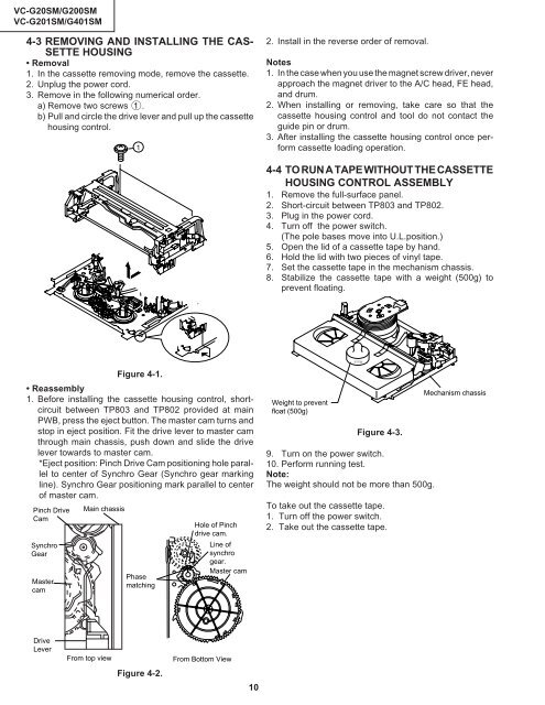
4-3 REMOVING AND INSTALLING THE CAS-<br />
SETTE HOUSING<br />
• Removal<br />
1. In the cassette removing mode, remove the cassette.<br />
2. Unplug the power cord.<br />
3. Remove in the following numerical order.<br />
a) Remove two screws 1.<br />
b) Pull and circle the drive lever and pull up the cassette<br />
housing control.<br />
1<br />
2. Install in the reverse order of removal.<br />
Notes<br />
1. In the case when you use the magnet screw driver, never<br />
approach the magnet driver to the A/C head, FE head,<br />
and drum.<br />
2. When installing or removing, take care so that the<br />
cassette housing control and tool do not contact the<br />
guide pin or drum.<br />
3. After installing the cassette housing control once perform<br />
cassette loading operation.<br />
4-4 TO RUN A TAPE WITHOUT THE CASSETTE<br />
HOUSING CONTROL ASSEMBLY<br />
1. Remove the full-surface panel.<br />
2. Short-circuit between TP803 and TP802.<br />
3. Plug in the power cord.<br />
4. Turn off the power switch.<br />
(The pole bases move into U.L.position.)<br />
5. Open the lid of a cassette tape by hand.<br />
6. Hold the lid with two pieces of vinyl tape.<br />
7. Set the cassette tape in the mechanism chassis.<br />
8. Stabilize the cassette tape with a weight (500g) to<br />
prevent floating.<br />
Figure 4-1.<br />
• Reassembly<br />
1. Before installing the cassette housing control, shortcircuit<br />
between TP803 and TP802 provided at main<br />
PWB, press the eject button. The master cam turns and<br />
stop in eject position. Fit the drive lever to master cam<br />
through main chassis, push down and slide the drive<br />
lever towards to master cam.<br />
*Eject position: Pinch Drive Cam positioning hole parallel<br />
to center of Synchro Gear (Synchro gear marking<br />
line). Synchro Gear positioning mark parallel to center<br />
of master cam.<br />
Pinch Drive<br />
Cam<br />
Synchro<br />
Gear<br />
Master<br />
cam<br />
Main chassis<br />
Phase<br />
matching<br />
Hole of Pinch<br />
drive cam.<br />
Line of<br />
synchro<br />
gear.<br />
Master cam<br />
Weight to prevent<br />
float (500g)<br />
500g<br />
Figure 4-3.<br />
9. Turn on the power switch.<br />
10. Perform running test.<br />
Note:<br />
The weight should not be more than 500g.<br />
To take out the cassette tape.<br />
1. Turn off the power switch.<br />
2. Take out the cassette tape.<br />
Mechanism chassis<br />
Drive<br />
Lever<br />
From top view<br />
Figure 4-2.<br />
From Bottom View<br />
10