VC-G20SM VC-G200SM VC-G201SM VC-G401SM - Cenatel
VC-G20SM VC-G200SM VC-G201SM VC-G401SM - Cenatel
VC-G20SM VC-G200SM VC-G201SM VC-G401SM - Cenatel

Sie wollen auch ein ePaper? Erhöhen Sie die Reichweite Ihrer Titel.
YUMPU macht aus Druck-PDFs automatisch weboptimierte ePaper, die Google liebt.
<strong>VC</strong>-<strong>G20SM</strong>/<strong>G200SM</strong><br />
<strong>VC</strong>-<strong>G201SM</strong>/<strong>G401SM</strong><br />
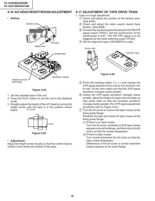
4-16 A/C HEAD HEIGHT ROUGH ADJUSTMENT<br />
• Setting<br />
Azimuth screw<br />
TiH screw<br />
Height screw<br />
Cassette tape<br />
4-17 ADJUSTMENT OF TAPE DRIVE TRAIN<br />
1. Tape run rough adjustment<br />
1 Check and adjust the position of the tension pole.<br />
(See 4-12.)<br />
2 Check and adjust the video search rewind back<br />
tension. (See 4-10.)<br />
3 Connect the oscilloscope to the test point for PB ATR<br />
signal output (TP201). Set the synchronism of the<br />
oscilloscope to EXT. The PB ATR signal is to be<br />
triggered by the head switching pulse (TP202).<br />
4 Set the alignment tape (VROUBZFS) to play.<br />
Guide roller<br />
Cassette Tape<br />
500g<br />
Weight to prevent<br />
float (500g)<br />
Tape<br />
Figure 4-24.<br />
1. Set the cassette tape in the unit.<br />
2. Press the PLAY button to put the unit in the playback<br />
mode.<br />
3. Roughly adjust the height of the A/C head by turning the<br />
height screw until the tape is in the position shown<br />
below. A/C head<br />
Figure 4-25.<br />
0.3mm<br />
Mechanism chassis<br />
• Adjustment<br />
Adjust the height screw visually so that the control head is<br />
visible 0.3mm below the bottom of the tape.<br />
Figure 4-26.<br />
5 Press the tracking button (+), (–) and change the<br />
ATR signal waveform from max to min and from min<br />
to max. At this time make sure that the ATR signal<br />
waveform changes nearly parallel.<br />
6 Unless the ATR signal waveform changes nearly<br />
parallel, adjust the height of supply side and take-up<br />
side guide roller so that the envelope waveform<br />
changes nearly parallel. (For ATR signal adjustment<br />
procedure refer to Figure 4-30.)<br />
7 Turn the tilt screw to remove the tape crease at the<br />
fixing guide flange.<br />
Playback the tape and check for tape crease at the<br />
fixing guide flange.<br />
(1) If there is no tape crease<br />
Turn the tilt screw clockwise so that tape crease<br />
appears once at the flange, and then return the tilt<br />
screw so that the crease disappears.<br />
(2) If there is tape crease<br />
Turn counterclockwise the tilt screw so that the<br />
tape crease disappears.<br />
(Reference) If the tilt screw is turned clockwise<br />
crease appears at the lower flange.<br />
18