VC-G20SM VC-G200SM VC-G201SM VC-G401SM - Cenatel
VC-G20SM VC-G200SM VC-G201SM VC-G401SM - Cenatel
VC-G20SM VC-G200SM VC-G201SM VC-G401SM - Cenatel

Sie wollen auch ein ePaper? Erhöhen Sie die Reichweite Ihrer Titel.
YUMPU macht aus Druck-PDFs automatisch weboptimierte ePaper, die Google liebt.
<strong>VC</strong>-<strong>G20SM</strong>/<strong>G200SM</strong><br />
<strong>VC</strong>-<strong>G201SM</strong>/<strong>G401SM</strong><br />
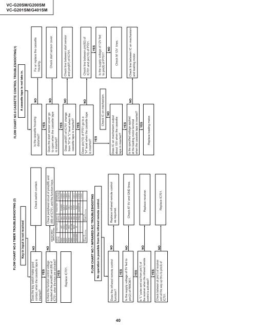
FLOW CHART NO.6 TIMER TROUBLESHOOTING (2)<br />
Key-in input is not received<br />
Does the key switch make good<br />
contact, when the cassette tape is<br />
inserted?<br />
YES<br />
Is there the function control voltage<br />
inputted at the pins(88) and (89) of<br />
IC701, when the keys are activated?<br />
YES<br />
Replace IC701.<br />
NO<br />
NO<br />
Check switch contact.<br />
Check peripheral circuit of pins(88) and<br />
(89) of IC701, and the function keys.<br />
SWITC FUNCTION SWITC FUNCTION TERMINAL<br />
Ref No. Ref No. VOLTAGE<br />
S805 SET S801 POWER 0.000V<br />
S806 CH(+) S802 EJECT 0.652V<br />
S807 PAUSE S803 MENU 1.864V<br />
S808 REC S804 CH(-) 2.561V<br />
S883 NO USE S881 PLAY<br />
S884/S885 REW S882 STOP 3.081V<br />
S886/S887 FF TP801 TEST 3.694V<br />
- - TP802 CASSETTE 4.279V<br />
- - - - 5.000V<br />
KEY-1 IN KEY-0 IN<br />
(Pin88 of IC701) (Pin89 of IC701)<br />
FLOW CHART NO.7 INFRARED R/C TROUBLESHOOTING<br />
No operation is possible from the infrared remote control.<br />
Does the infrared remote control<br />
function?<br />
NO<br />
Replace infrared remote control<br />
as required.<br />
YES<br />
Is the supply voltage of 5V fed to NO<br />
pin(2) of RMC801. Check AT 5V and GND lines.<br />
YES<br />
Is "L" pulse sent out from pin(1) of<br />
the receiver when the infrared remote<br />
control is activated?<br />
NO<br />
Replace receiver.<br />
YES<br />
Check between at pin(1) of receiver<br />
and all the way up thru to pin(4) of<br />
IC701.<br />
NO<br />
Replace IC701.<br />
FLOW CHART NO.8 CASSETTE CONTROL TROUBLESHOOTING(1)<br />
A cassette tape is not take in.<br />
Is the cassette housing<br />
distorted?<br />
NO<br />
Fix or replace the cassette<br />
housing.<br />
YES<br />
Does the start sensor cover go<br />
to open when the cassette tape<br />
is inserted?<br />
YES<br />
Does pin(87) of IC701 change<br />
from "H" to "L" level when the<br />
cassette tape is inserted?<br />
NO<br />
NO<br />
Check start sensor cover.<br />
Check line between start sensor<br />
and pin(87) of IC701.<br />
YES<br />
YES<br />
Does pin(10) of P701 go to a<br />
"H" level when the cassette tape<br />
is inserted?<br />
Does IC on mechanism output<br />
about 10V when the cassette<br />
tape in inserted?<br />
YES<br />
YES<br />
NO<br />
Is the specified voltage applied<br />
at the loading motor terminal<br />
when the cassette tape is inserted?<br />
NO<br />
Check IC on mechanism.<br />
NO<br />
Check line between pin(92) of<br />
IC701 and pin(10) of P701.<br />
YES<br />
Is the supply voltage of 12V fed<br />
to pin(8) of P701?<br />
NO<br />
Check M 12V lines.<br />
Check line between IC on mechanism<br />
and loading motor.<br />
Replace loading motor.<br />
A/D KEY INPUT<br />
SPECIFICATION:-<br />
40