Bedienungsanleitung - Viessmann Modellspielwaren GmbH
Bedienungsanleitung - Viessmann Modellspielwaren GmbH
Bedienungsanleitung - Viessmann Modellspielwaren GmbH

Erfolgreiche ePaper selbst erstellen
Machen Sie aus Ihren PDF Publikationen ein blätterbares Flipbook mit unserer einzigartigen Google optimierten e-Paper Software.
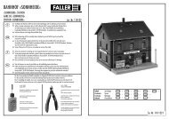
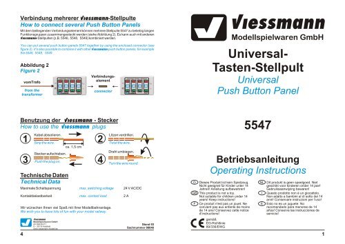
Verbindung mehrerer <strong>Viessmann</strong>-Stellpulte<br />
How to connect several Push Button Panels<br />
Verbindungselement<br />
Mit dem beiliegenden Verbindungselementkönnen mehrere Stellpulte 5547 zu beliebig langen<br />
Funktionsgruppen zusammengesteckt werden (siehe Abbildung 2). Es kann auch mit anderen<br />
<strong>Viessmann</strong>-Stellpulten (z.B. 5546, 5548, 5549) kombiniert werden.<br />
You can put several push button panels 5547 together by using the enclosed connector (see<br />
figure 2). It’s also possible to combine it with other <strong>Viessmann</strong> push button panels, for example<br />
the 5546, 5548, 5549.<br />
Abbildung 2<br />
Figure 2<br />
vomTrafo<br />
from the<br />
transformer<br />
Universal Tasten - Stellpult<br />
viessmann 5547<br />
Universal-<br />
Tasten-Stellpult<br />
connector<br />
Universal Tasten - Stellpult<br />
viessmann 5547<br />
<strong>Viessmann</strong><br />
<strong>Modellspielwaren</strong> <strong>GmbH</strong><br />
Universal<br />
Push Button Panel<br />
Benutzung der <strong>Viessmann</strong> - Stecker<br />
How to use the <strong>Viessmann</strong> plugs<br />
Technische Daten<br />
Technical Data<br />
Maximale Schaltspannung<br />
Kontaktbelastbarkeit<br />
max. switching voltage<br />
max. contact load<br />
Wir wünschen Ihnen viel Spaß mit Ihrer Modellbahnanlage.<br />
We wish you to have lots of fun with your model railway.<br />
4<br />
Kabel abisolieren.<br />
1 2<br />
Strip the wire.<br />
Stecker aufschieben.<br />
ca. 1,5 cm<br />
3 Push the plug on. 4<br />
<strong>Viessmann</strong><br />
<strong>Modellspielwaren</strong> <strong>GmbH</strong><br />
Am Bahnhof 1<br />
D - 35116 Hatzfeld<br />
www.viessmann-modell.de<br />
Litzen verdrillen.<br />
Twist the wire.<br />
Draht umbiegen.<br />
Turn the wire round.<br />
24 V AC/DC<br />
2 A<br />
Stand 03<br />
Sachnummer 98646<br />
5547<br />
Betriebsanleitung<br />
Operating Instructions<br />
D Dieses Produkt ist kein Spielzeug.<br />
Nicht geeignet für Kinder unter 14<br />
Jahren! Anleitung aufbewahren!<br />
GB This product is not a toy.<br />
Not suitable for children under 14<br />
years! Keep instructions!<br />
F Ce produit n'est pas un jouet. Ne<br />
convient pas aux enfants de moins<br />
de 14 ans! Conservez cette notice<br />
d’instructions!<br />
gemäß<br />
EG-Richtlinie<br />
89/336/EWG<br />
NL<br />
I<br />
E<br />
Dit produkt is geen speelgoed. Niet<br />
geschikt voor kinderen onder 14 jaar!<br />
Gebruiksaanwijzing bewaren!<br />
Questo prodotto non è un giocattolo.<br />
Non adatto a bambini al di sotto dei 14<br />
anni! Conservare instruzioni per l’uso!<br />
Esto no es un juguete. No<br />
recomendado para menores de 14<br />
años! Conserva las instrucciones de<br />
servicio!<br />
1
t<br />
Einleitung<br />
Introduction<br />
Das Stellpult 5547 von <strong>Viessmann</strong> besitzt 8 separate Momenttaster in 4 Gruppen für die<br />
Steuerung von zweibegriffigen Signalen.<br />
Das Stellpult eignet sich außerdem zur Ansteuerung der <strong>Viessmann</strong>-Standard-Licht-Blockund<br />
Sperrsignale über den Signalsteuerbaustein 5210 (ohne Zugbeeinflussung) oder über das<br />
Signalmodul 5221 (mit Zugbeeinflussung).<br />
Für die Steuerung von dreibegriffigen Signalen (Vor- und Hauptsignale) verwenden Sie bitte<br />
das speziell hierfür entwickelte Stellpult 5546.<br />
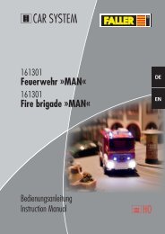
Anschluß von zweibegriffigen Signalen<br />
How to connect signals with 2 aspects<br />
An dem Stellpult 5547 können zweibegriffige Signale angeschlossen werden. Dazu werden die<br />
drei blauen Signalkabel mit gelber, roter und grüner Markierung mit dem Stellpult verbunden,<br />
wie es in Abbildung 1 dargestellt ist. Pro Schaltgruppe dürfen maximal 2 Signale angeschlossen<br />
werden.<br />
To the push button panel 5547 you can connect signals with two aspects. For that the three<br />
yellow, red and green marked blue wires of the signal have to be connect to the push button<br />
panel like it is shown in figure 1. You can connect maximum 2 signals to each push button<br />
group.<br />
The push button panel 5547 from <strong>Viessmann</strong> has got eight separate momentary contacts in<br />
four groups for controlling signals with two aspects.<br />
The panel can also be used for controlling the standard-block-signals from <strong>Viessmann</strong> by the<br />
control modul for colour-light-signals 5210 (without return indication) or by the colour-light-signal<br />
modul 5221 (with return indication).<br />
z.B.<br />
4021 (H0)<br />
4441 (N)<br />
4941 (TT)<br />
Abbildung 1<br />
Figure 1<br />
To control the <strong>Viessmann</strong> standard-light-signals with three aspects (main signals and distant<br />
signals) please use the push button panel 5546. It has been developed especially for this kind of<br />
items.<br />
In den Anschlußplänen dieser Anleitung finden Sie<br />
häufig das obenstehende Symbol. Es kennzeichnet<br />
eine Leitungsverbindung. Die sich hier kreuzenden<br />
Leitungen müssen an einer beliebigen Stelle ihres<br />
Verlaufs elektrisch leitend miteinander in Verbindung<br />
stehen. Der Verbindungspunkt muß also nicht<br />
exakt an der eingezeichneten Stelle sitzen, sondern<br />
kann z.B. zu einem Stecker, welcher sich an einer<br />
der kreuzenden Leitungen befindet, verlagert werden.<br />
In the connection diagrams of this instruction you<br />
can often see the above shown symbol. It describes<br />
a wire connection. The wires which here are crossing<br />
themselves have to be connected electrically at<br />
any point on their way. So the connection point<br />
doesn’t need to be exactly at the shown location. It<br />
can be moved e.g. to a plug which is connected to<br />
one of the crossing wires.<br />
z.B.<br />
4020 (H0)<br />
4440 (N)<br />
4940 (TT)<br />
z.B.<br />
4011 (H0)<br />
4411 (N)<br />
4811 (Z)<br />
4911 (TT)<br />
braun<br />
brown<br />
braun<br />
brown<br />
blau<br />
blue<br />
b<br />
l<br />
a<br />
u<br />
b<br />
l<br />
u<br />
e<br />
Universal Tasten - Stellpult<br />
<strong>Viessmann</strong><br />
Lichttransformator 5200<br />
Sekundär<br />
Primär 230 V 50/60 Hz<br />
16 V ~<br />
Sekundär 52 VA max. 3,25 A<br />
IP 40 ta 25°C<br />
Nur für trockene Räume<br />
Gefertigt nach<br />
VDE 0551<br />
EN 60742<br />
Primär<br />
230 V ~<br />
viessmann 5547<br />
braun<br />
brown<br />
Achtung!<br />
Attention!<br />
Alle Anschlußarbeiten sind nur bei abgeschalteter Betriebsspannung<br />
durchzuführen!<br />
Make sure that the power supply is switched off when you connect the wires !<br />
Die Stromquellen müssen so abgesichert sein, daß es im Falle eines Kurzschlusses<br />
nicht zum Kabelbrand kommen kann. Verwenden Sie nur<br />
handelsübliche und nach VDE / EN gefertigte Modellbahntransformatoren!<br />
The power sources must be protected to prevent the risk of burning wires. Only<br />
use VDE-tested special model train transformers for the power supply!<br />
braun<br />
brown<br />
gelb<br />
yellow<br />
blau<br />
blue<br />
zum Gleis<br />
gn<br />
viessmann<br />
Steuermodul für<br />
Licht-Blocksignal 5221<br />
+<br />
14 - 16V<br />
Vorsignal -<br />
Steuerung<br />
blau<br />
blue<br />
gelb<br />
yellow<br />
2<br />
3