102386 Kurzbedienungsanleitung FOCX32 ... - Elcon Systemtechnik
102386 Kurzbedienungsanleitung FOCX32 ... - Elcon Systemtechnik
102386 Kurzbedienungsanleitung FOCX32 ... - Elcon Systemtechnik

Erfolgreiche ePaper selbst erstellen
Machen Sie aus Ihren PDF Publikationen ein blätterbares Flipbook mit unserer einzigartigen Google optimierten e-Paper Software.
coax<br />
Fiber Optical Coax MDU <strong>FOCX32</strong><br />
mit Fernspeisenetzteil ODER mit 230-V-Netzteil<br />
with Remote Power Supply Module OR 230 V Power Pack<br />
Installationsanleitung<br />
Installation manual<br />
© ELCON <strong>Systemtechnik</strong> GmbH 2009 Art.-Nr. <strong>102386</strong>
Sicherheitshinweise<br />
<strong>FOCX32</strong><br />
• Bitte lesen Sie die Warnhinweise, Sicherheitsbestimmungen sowie die Installationsanleitung<br />
gewissenhaft durch, bevor Sie mit der Installation des ELCONnect coax<br />
<strong>FOCX32</strong> beginnen. Nur so können Sie das Gerät in seinem vollen Funktionsumfang<br />
nutzen und Schäden durch unsachgemäßen Gebrauch vermeiden (Feuer, Elektroschocks,<br />
Verletzungen usw.). Bewahren Sie die Installationsanleitung sorgfältig auf.<br />
• Der ELCONnect coax <strong>FOCX32</strong> entspricht dem aktuellen Stand der Technik und den<br />
anerkannten sicherheitstechnischen Regeln.<br />
• Verwenden Sie beim Auspacken des Gerätes keine spitzen Gegenstände, um Beschädigungen<br />
an Gehäuse oder Kabeln zu vermeiden.<br />
• Betreiben Sie das Gerät und die mitgelieferten Teile (Kabel usw.) nur in einwandfreiem<br />
Zustand und unter strenger Beachtung der Installationsanleitung.<br />
• Arbeiten am Gerät einschließlich Öffnen des Gerätes darf nur autorisiertes Fachpersonal<br />
durchführen. Dabei sind die ESD-Schutzmaßnahmen nach DIN 100 015 zu beachten.<br />
Außer den in diesem Handbuch beschriebenen Handlungen dürfen keine Änderungen<br />
am Gerät sowie an den mitgelieferten Teilen (Kabel usw.) vorgenommen werden.<br />
• Achtung: Gefährliche elektrische Spannungen! Vor Öffnen des Modems unbedingt<br />
Netzstecker ziehen und Anschlusskabel von den Schnittstellen entfernen!<br />
• Vermeiden Sie Arbeiten am Gerät und dessen Komponenten bei Gewitter (Trennen<br />
und Herstellen von Kabelverbindungen).<br />
• Achten Sie beim Anschluss des Gerätes auf die richtige Versorgungsspannung (→<br />
Technische Daten)!<br />
• Das Modem besitzt keine eigene Trennvorrichtung zur Unterbrechung der Spannungsversorgung,<br />
da es für Dauerbetrieb ausgelegt ist. Achten Sie daher bei 230-V-<br />
Netzspeisung darauf, dass der Netzstecker stets leicht zugänglich ist.<br />
• Verlegen Sie Netz- und Anschlusskabel so, dass eine Unfallgefahr durch Stolpern oder<br />
Hängen bleiben ausgeschlossen wird.<br />
• Betreiben Sie das Gerät nur im Temperaturbereich zwischen -20°C und +60°C!<br />
• Schützen Sie das Gerät vor direkter Sonneneinstrahlung und vor Feuchtigkeit.<br />
• Wenn Sie das Gerät aus einer kalten Umgebung in eine wärmere Umgebung bringen,<br />
dann kann dies zu einer Betauung des Gerätes führen. Betaute Geräte dürfen nicht in<br />
Betrieb genommen werden. Warten Sie mit der Inbetriebnahme, bis das Gerät trocken<br />
ist.<br />
• An den Schnittstellen des ELCONnect coax <strong>FOCX32</strong> dürfen nur Geräte angeschlossen<br />
werden, die die elektrischen Sicherheitsbestimmungen nach EN 60950 erfüllen<br />
und das CE-Zeichen tragen.<br />
• Alle angeschlossenen Geräte müssen passende Steckverbindungen besitzen, anderenfalls<br />
sind geeignete Adapter zu verwenden.<br />
• Alle angeschlossenen Geräte dürfen nur an den vorgesehenen Schnittstellen betrieben<br />
werden.<br />
• Beachten Sie die Installations- und Sicherheitshinweise und halten Sie diese ein.<br />
Version: 2009/01/29
<strong>FOCX32</strong><br />
• Warnung vor gefährlicher Laserstrahlung - Laser Klasse 1<br />
Die zugängliche Laserstrahlung ist unter vernünftigerweise vorhersehbaren Bedingungen<br />
ungefährlich, da die Laser bei bestimmungsgemäßem Gebrauch so eingekapselt<br />
sind, dass ein Austritt von Strahlung vollständig verhindert wird. Um irreparablen Augenschäden<br />
vorzubeugen, blicken Sie niemals direkt oder indirekt (z.B. über Spiegel)<br />
in den Laserstrahl, d.h. auf das Ende des Glasfaserkabels bzw. des entsprechenden<br />
Steckverbinders. Um ein unbeabsichtigtes Hineinsehen in den Laserstrahl zu vermeiden,<br />
sind offene Kabelenden bzw. Steckverbinder grundsätzlich mit einer Staubschutzkappe<br />
zu verschließen und im Laserbereich gut reflektierende Flächen abzudecken<br />
oder zu entfernen.<br />
Um die hervorragenden Übertragungseigenschaften von Glasfaserkabel zu erhalten,<br />
darf dieses nicht geknickt werden. Um ein Knicken des Glasfaserkabels zu vermeiden,<br />
ist es in die vorgesehene Aufwickelvorrichtung (Fiber-Management) einzulegen. Es<br />
darf ein Umlenkradius von 60 mm bzw. der kleinste zulässige Biegeradius von 30 mm<br />
nicht unterschritten werden. Siehe hierzu auch die TS 0011/02.96 (Schaltkabel für<br />
Fernmeldelinien; Glasfaser-Schaltkabel der Ausführung SVH mit Einmodenfaser).<br />
Des Weiteren sind offene Kabelenden und Steckverbinder mit einer Staubschutzkappe<br />
zu versehen, um Verschmutzung und damit verbundene zusätzliche Dämpfung zu<br />
vermeiden. Aus diesem Grund ist auch das Berühren der Faserendflächen zu unterlassen.<br />
Die eventuell notwendige Reinigung der Glasfasersteckverbinder sollte mit speziell<br />
dafür bestimmten Reinigungspads und -materialien erfolgen. Verwenden Sie niemals<br />
Druck- oder Atemluft, um Verunreinigungen wegzublasen, damit diese nicht in<br />
die Augen oder in die Lunge gelangen.<br />
Sehr geehrte Kundin, sehr geehrter Kunde<br />
mit dem ELCONnect coax <strong>FOCX32</strong> haben Sie ein Gerät erhalten, welches nach dem neuesten<br />
Stand der Technik entwickelt und unter höchsten Anforderungen gefertigt wurde. Zusammen<br />
mit einem ELCONnect coax Client bildet der <strong>FOCX32</strong> ein vollständiges System zur Datenübertragung<br />
über existierende Koaxialkabel auf sehr ökonomische und flexible Art und Weise.<br />
Sollte einmal etwas nicht wie beschrieben funktionieren, nehmen Sie bitte mit Ihrem Anbieter<br />
oder Händler Kontakt auf, von dem Sie dieses Gerät erworben haben. Dieser verfügt über die<br />
notwendigen Fachkenntnisse und wird Ihnen gern weiterhelfen.<br />
Wir wünschen Ihnen viel Freude mit Ihrem <strong>FOCX32</strong>.<br />
Version: 2009/01/29 1
Safety precautions<br />
2<br />
<strong>FOCX32</strong><br />
• Please read carefully the warnings and safety precautions in this installation manual<br />
before you start installation of your ELCONnect coax <strong>FOCX32</strong>. These instructions<br />
enable you to use the full functionality of the device and to avoid damage which may<br />
result from improper use (fire, electric shock, injuries etc.). Keep this manual at a safe<br />
place.<br />
• The ELCONnect coax <strong>FOCX32</strong> has been manufactured according to state-of-the-art<br />
technology and complies with the generally accepted safety standards.<br />
• Do not use sharp-edged tools for unpacking the device: they could damage cables or<br />
the enclosure.<br />
• The device and its accessories (cable etc.) shall be operated only in faultless condition,<br />
while strictly observing these installation instructions.<br />
• Only authorized personnel are allowed to open the device and to carry out interventions<br />
in the device. Please observe the protective measures with respect to electrostatic<br />
discharge as per DIN 100 015. Manipulations on the device or attached parts (cables<br />
etc.) other than those described in this manual are not allowed.<br />
• Warning: Dangerous electric voltage! Before opening the modem, remove the mains<br />
plug and disconnect the cables from the interfaces!<br />
• Refrain from interventions in the device and its parts during thunderstorms (in particular,<br />
avoid plugging and unplugging of cables).<br />
• When connecting the device, pay attention to comply with the required mains voltage.<br />
(→ Technical data)!<br />
• The modem has no separate switch for interrupting the power supply, since it has been<br />
designed for continuous operation. So make sure that the mains plug is always easily<br />
accessible when 230 V supply voltage is applied.<br />
• Lay the power supply and connection cables in a way to prevent accidents (such as<br />
tripping over the cables).<br />
• The device shall be operated only between -20°C and +60°C.<br />
• Protect the device from direct sun radiation and extreme humidity.<br />
• When the device is taken from a cold environment into a warmer one, it may be bedewed.<br />
In this case the equipment must not be put into operation. So please wait until<br />
the modem is dry again.<br />
• Connect to the ELCONnect coax <strong>FOCX32</strong> interfaces only such terminal devices<br />
which meet the safety requirements acc. to EN 60950 and which are labelled with the<br />
CE symbol.<br />
• The terminal devices shall have appropriate connectors; otherwise adequate adapters<br />
have to be used.<br />
• Connected equipment shall only be operated at the corresponding interfaces that have<br />
been designed for them.<br />
• Pay attention to the instructions on installation and safety and comply with them.<br />
Version: 2009/01/29
<strong>FOCX32</strong><br />
• Warning of dangerous laser radiation – Class 1 laser<br />
Subject to the reasonably foreseeable conditions, the accessible laser radiation is nonhazardous,<br />
since the laser beams during normal use are fully encapsulated which prevents<br />
them from being radiated. In order to protect your eyes from irreparable damage,<br />
do never look directly or indirectly (e.g. via mirror) into the laser beam, i.e. at the edge<br />
of the fiber cable or the related connector. To avoid accidentally looking into the laser<br />
beam, open cable ends or connectors, respectively, shall be sealed with a dust cover,<br />
while reflecting surfaces within the laser range need to be removed or covered at least.<br />
To maintain the supreme transmission performance of fiber cable, it must not be<br />
kinked. Therefore the fiber cable shall be placed in the special wind-up unit (Fiber<br />
Management). Hereby the winding radius must not be lesser than 60 mm, with a<br />
minimum admissible bending radius of 30 mm. For this, see also the provisions in the<br />
Technical Specification TS 0011/02.96 (switching cable for telecommunication lines;<br />
SVH-type fiber switching cable with single-mode fiber). Further, open cable ends<br />
shall be protected by a dust cover, to protect them from being polluted and prevent the<br />
extra attenuation caused by this. For the same reason, do not touch the fiber ends. For<br />
cleaning the fiber connectors (if needed), special cleansing pads and materials should<br />
be applied. Do never try to blow off dust particles by using pressure air or your breath:<br />
otherwise tiniest particles could get into your eyes or the lungs.<br />
Dear Customer,<br />
Your ELCONnect coax <strong>FOCX32</strong> is a product that represents state-of-the-art technology and<br />
has been manufactured in compliance with highest quality standards. In connection with the<br />
ELCONnect coax Client the <strong>FOCX32</strong> forms a fully-functioning system for a both economical<br />
and flexible data transfer via the existing coaxial cable network.<br />
Should it happen that something is acting up other than described, please contact your provider<br />
or salesman who has offered you the device. He will have the necessary knowledge to<br />
offer you the required support.<br />
And now enjoy your <strong>FOCX32</strong>!<br />
Version: 2009/01/29 3
Inhalt<br />
4<br />
<strong>FOCX32</strong><br />
DEUTSCH .................................................................................................................................... 6<br />
1 Technische Beschreibung des ELCONnect-coax-Systems ................................... 6<br />
1.1 Anwendungsbereich ................................................................................................... 6<br />
1.2 Allgemeine Merkmale ................................................................................................ 7<br />
1.3 Funktionsweise ........................................................................................................... 7<br />
1.4 Aufbau ELCONnect coax <strong>FOCX32</strong> ........................................................................... 9<br />
1.5 Stromversorgung ........................................................................................................ 9<br />
2 Installation des ELCONnect coax <strong>FOCX32</strong> ........................................................ 10<br />
2.1 Lieferumfang ............................................................................................................ 10<br />
2.2 Montagehinweise ..................................................................................................... 10<br />
2.3 Wahl des Montageortes / Befestigung des Gerätes .................................................. 10<br />
2.4 Befestigung der Wandhalterung & Wandmontage .................................................. 11<br />
2.5 Montage der Koaxialkabel-Anschlussadapter .......................................................... 12<br />
2.6 Montage des SC/PC-Connectors am Lichtwellenleiter und Anschluss des<br />
Glasfaserkabels ........................................................................................................ 13<br />
2.6.1 QuickAssembly Handgerät für Steckermontage .............................................. 14<br />
2.6.2 Spleißgerät ........................................................................................................ 14<br />
2.6.3 Feldkonfektionierbare Stecker ......................................................................... 15<br />
2.6.4 Montage des Glasfaserkabel ............................................................................. 16<br />
2.7 Potenzialausgleich des ELCONnect coax <strong>FOCX32</strong> ................................................ 16<br />
2.8 Anschließen der Verbindungskabel ......................................................................... 17<br />
2.9 Netzanschluss / Stromversorgung ............................................................................ 18<br />
2.10 Sicherungen für Fernspeiseoptionen ........................................................................ 18<br />
2.11 Anzeigeelemente (LEDs) ......................................................................................... 21<br />
2.12 Inbetriebnahme ......................................................................................................... 22<br />
2.13 Pflege und Wartung .................................................................................................. 22<br />
2.14 Abbau des Gerätes .................................................................................................... 22<br />
3 Technische Daten ................................................................................................... 22<br />
4 Wichtige Hinweise ................................................................................................. 24<br />
4.1 Herstellererklärung ................................................................................................... 24<br />
4.2 Recycling .................................................................................................................. 24<br />
4.3 WEEE-Directive ....................................................................................................... 24<br />
4.4 Gewährleistung ......................................................................................................... 24<br />
4.5 Rechte und Warenzeichen ........................................................................................ 25<br />
Version: 2009/01/29
<strong>FOCX32</strong><br />
Contents<br />
ENGLISH ................................................................................................................................... 26<br />
1 Technical description of the ELCONnect coax System ...................................... 26<br />
1.1 Scope of application ................................................................................................. 26<br />
1.2 General characteristics ............................................................................................. 27<br />
1.3 Functional principle .................................................................................................. 27<br />
1.4 Structure of the ELCONnect coax <strong>FOCX32</strong> ............................................................ 29<br />
1.5 Power supply ............................................................................................................ 29<br />
2 Installation of the ELCONnect coax <strong>FOCX32</strong> .................................................... 30<br />
2.1 Scope of delivery ...................................................................................................... 30<br />
2.2 Mounting instructions .............................................................................................. 30<br />
2.3 Selecting the installation place / Fixing the equipment ............................................ 30<br />
2.4 Fixing of the wall brackets and wallmounting ......................................................... 31<br />
2.5 Mounting the coaxial cable adapter connector ......................................................... 32<br />
2.6 Mounting of the SC/PC-Connector on the optical fiber and connection of the fiber<br />
cable ......................................................................................................................... 33<br />
2.6.1 QuickAssembly Tool for Connector Mounting ............................................... 34<br />
2.6.2 Splice unit ......................................................................................................... 34<br />
2.6.3 Pre-assembled connectors ................................................................................ 35<br />
2.6.4 Assembly of the optical fiber cable .................................................................. 36<br />
2.7 Potential equalization of the ELCONnect coax <strong>FOCX32</strong> ........................................ 36<br />
2.8 Installation of the connection cables ........................................................................ 37<br />
2.9 Mains connection / Power supply ............................................................................ 38<br />
2.10 Fuses for remote power feeding options .................................................................. 38<br />
2.11 Display elements (LEDs) ......................................................................................... 41<br />
2.12 Putting into operation ............................................................................................... 42<br />
2.13 Maintenance ............................................................................................................. 42<br />
2.14 Uninstallation of the device ...................................................................................... 42<br />
3 Technical data ........................................................................................................ 42<br />
4 Important notes ...................................................................................................... 44<br />
4.1 Manufacturer´s declaration ...................................................................................... 44<br />
4.2 Recycling .................................................................................................................. 44<br />
4.3 WEEE-Directive ....................................................................................................... 44<br />
4.4 Warranty ................................................................................................................... 44<br />
4.5 Rights and trademarks .............................................................................................. 45<br />
Version: 2009/01/29 5
DEUTSCH<br />
1 Technische Beschreibung des ELCONnect-coax-Systems<br />
1.1 Anwendungsbereich<br />
6<br />
<strong>FOCX32</strong><br />
Die ELCON <strong>Systemtechnik</strong> GmbH stellt mit der ELCONnect-coax-Technik ein System zur<br />
Verfügung, welches zur Verteilung von Datendiensten, Sprache sowie Multimediaformaten<br />
auf bestehenden unidirektionalen Kabel-TV-Netzen genutzt werden kann. Aufgrund der flexiblen<br />
Konfigurierbarkeit des Systems und der einfachen und kostengünstigen Installation<br />
und Erweiterbarkeit kann diese Technologie in zahlreichen unterschiedlichen Anwendungsszenarien<br />
eingesetzt werden, z.B.:<br />
• Bereitstellung von Breitbandanschlüssen in Hotelzimmern<br />
• Verteilung von Breitbanddiensten bzw. als Netzzugang für die „Letzte Meile“<br />
• IP-Telefonie mit geeigneter Hardware und geeignetem Serviceangebot möglich<br />
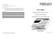
Bild 1: Anwendungen allgemein<br />
Die vorliegende Dokumentation beschreibt den ELCONnect coax <strong>FOCX32</strong>, welcher als Fiber<br />
Optical Coax Master mit optischer Schnittstelle konzipiert ist. Das ELCONnect-coax-System<br />
besteht aus dem netzseitig zu installierenden optischen Master und dem teilnehmerseitigen<br />
Client. Dabei bildet der <strong>FOCX32</strong> den Übergabepunkt zu externen Übertragungssystemen – er<br />
stellt den Gateway zwischen dem coax-Netzwerk und dem ethernetbasierten IP-Anschluss<br />
dar. Der Client dient zum Anschluss der Endgeräte der Teilnehmer. Dafür stehen sowohl<br />
Ethernetschnittstellen als auch analoge Telefon-Ports zur Verfügung.<br />
Folgende Hardwarekomponenten können für das ELCONnect-coax-Netz eingesetzt werden:<br />
Version: 2009/01/29
<strong>FOCX32</strong><br />
ELCONnect coax<br />
Master32<br />
Gateway Übertragungsstrecke<br />
ELCONnect coax<br />
OutdoorMaster OCM32<br />
ELCONnect coax<br />
Fiber Optical Coax MDU<br />
<strong>FOCX32</strong><br />
ELCONnect coax<br />
OutdoorMaster OCM64<br />
ELCONnect coax<br />
OutdoorRepeater OCR32<br />
Teilnehmerseitiger<br />
Netzabschluss<br />
ELCONnect coax<br />
Client Base<br />
ELCONnect coax<br />
Client VoIP<br />
Detaillierte Informationen zu den weiteren Komponenten erhalten Sie unter<br />
www.elcon-system.com<br />
1.2 Allgemeine Merkmale<br />
• Datenübertragung von 200 Mbit/s (brutto) bzw. bis zu 100 Mbit/s (netto) über das Koaxialkabelnetz<br />
einer TV-Anlage<br />
• Verwenden von ethernettypischen Protokollen (TCP/IP, UDP,...)<br />
• einfaches Anschließen an die physikalischen Schnittstellen<br />
• keine Installation von Treibern notwendig<br />
• hohe Sicherheit durch eine verschlüsselte Übertragung und das Vermeiden von Peerto-Peer-Traffic<br />
innerhalb eines ELCONnect-coax-Systems (Vermeiden des Zugriffs<br />
der Nutzer / Endkunden auf ELCONnect-coax-Geräte (eigene / fremde Clients oder<br />
Master) innerhalb desselben Segments)<br />
1.3 Funktionsweise<br />
Die ELCONnect-coax-Technologie verwendet von TV-Signalen ungenutzte Frequenzbereiche.<br />
Durch die Einspeisung des Coax-Signals werden die bereits vorhandenen Fernseh- und<br />
Radiokanäle nicht beeinflusst, da diese im Frequenzbereich weiter oben liegen (Bild 2).<br />
coax-Signale TV- & Rundfunk-Frequenzen<br />
4 34 47 862 f in MHz<br />
Bild 2: Frequenzverteilung<br />
Version: 2009/01/29 7
<strong>FOCX32</strong><br />
Das Datensignal wird bidirektional über das TV-Kabelverteilnetz übertragen. Der Aufbau der<br />
Koaxialverkabelung (z.B. Baum- oder Sternstruktur) ist dabei unkritisch. Alle ELCONnectcoax-Modems<br />
haben gleichberechtigten Zugriff auf das Medium. Für die Übertragung wird<br />
ein Multiplex-Verfahren genutzt, bei dem eine automatische Anpassung der Datenrate in Abhängigkeit<br />
von der Verbindungsqualität ermöglicht wird. Dieses robuste und effektive Übertragungsverfahren<br />
ermöglicht selbst unter widrigen Umständen eine zuverlässige Datenübertragung.<br />
Beim Einsatz mehrerer Geräte teilt sich die Datenrate dynamisch auf.<br />
Die Geräte werden über eine Konfigurationsdatei konfiguriert. Dabei werden alle für die<br />
Übertragung notwendigen Parameter eingestellt. Das sind unter anderem Bandbreitenzuordnung<br />
zu den Clients, Quality-Of-Service-Parameter, Zugangsberechtigungen oder auch Übertragungspegel.<br />
Bei Bedarf können Frequenzbereiche für die Übertragung ausgeblendet werden,<br />
was unter Umständen in Hotelnetzen für Pay-TV-Signale notwendig ist. Auch die Absenkung<br />
über einen gesamten Frequenzbereich ist möglich.<br />
Der optische Master ist die Schnittstelle zwischen dem TV-Kabelverteilnetz und dem bidirektionalen<br />
Telekommunikationsnetz. Der <strong>FOCX32</strong> wird beispielsweise an einen Router angeschlossen<br />
und speist das Datensignal am Ausgang der Kopfstelle oder am Netzknoten in das<br />
Koaxialkabelnetz ein. Das Signal wird an alle TV-Anschlussdosen bis zu einer Entfernung<br />
von max. 750 m (je nach Umgebungsbedingung) verteilt. Die Signaleinkopplung der Clients<br />
erfolgt an der TV-Dose in der Wohnung des Kunden über den im Lieferumfang enthaltenen<br />
TV-Zweigeräteverteiler. Das ist einfach und ohne zusätzliche Kosten realisierbar, da alle erforderlichen<br />
Komponenten bereits mitgeliefert werden. Über ein Patchkabel wird der Client<br />
mit der Netzwerkkarte des PCs verbunden. Der Endkunde ist damit in der Lage, den "Internetzugang"<br />
ohne weiteren Konfigurationsaufwand des anzuschließenden PCs zu nutzen.<br />
Die Aufbereitung bzw. Modulation der Daten zur Übertragung auf dem Koaxialkabelnetz<br />
inklusive der Bereitstellung aller Schnittstellen für Glasfaser- und Koaxialanschluss wird<br />
durch die ELCONnect-coax-Modems gewährleistet.<br />
Die Modems werden durch ihre Funktionalität nach Anschluss an einen Server oder Router<br />
(<strong>FOCX32</strong>) bzw. an die Netzwerkkarte des jeweiligen PCs oder Routers (Client) sowohl als<br />
Sender als auch als Empfänger der zu übertragenden Daten eingesetzt. Das ELCONnect-coax-<br />
System fungiert dabei als Brücke (Bridge) zwischen einem Server oder Router und an diesen<br />
angeschlossene Endgeräte wie PC oder Settop-Boxen. Zum Beispiel werden IP-Adressen weiterhin<br />
wie in einem normalen PC-Netzwerk vom Server oder Router dynamisch (DHCP) oder<br />
statisch vergeben an die angeschlossenen Endgeräte wie PC.<br />
Die Modems sind damit in der Lage, Dienste wie zum Beispiel einen Internetanschluss, im<br />
Kabel-TV-Netz bereitzustellen. Um die Sicherheit in einem großen Netzwerk zu gewährleisten,<br />
können die Clients nicht untereinander, sondern nur mit dem dazugehörigen optischen<br />
Master kommunizieren.<br />
8<br />
Version: 2009/01/29
<strong>FOCX32</strong><br />
1.4 Aufbau ELCONnect coax <strong>FOCX32</strong><br />
Nachfolgende schematische Darstellung zeigt die wesentlichen Komponenten des<br />
ELCONnect coax <strong>FOCX32</strong> sowie deren Position im Gerät. Für die Installation sind dabei die<br />
Testbuchse für Messungen und das Sicherungsfeld von Bedeutung.<br />
Netzteil<br />
Bi-direktionaler<br />
Single Fiber<br />
Transceiver<br />
Testpunkt<br />
F-Buchse für<br />
Spektrum des<br />
DATA-Signals<br />
ELCONnect<br />
coax Master-<br />
Module<br />
Ausgang TV/DATA<br />
Client-Seite<br />
(SIGNAL OUT)<br />
1.5 Stromversorgung<br />
Eingang TV<br />
Headend-Seite<br />
(TV IN)<br />
Fernspeiseweiche<br />
Bild 3: Aufbau des ELCONnect coax <strong>FOCX32</strong><br />
Sicherungsfeld<br />
für Fernspeisung<br />
Kabeldurchführung<br />
für<br />
Glasfaser<br />
Netzanschluss<br />
Fiber-<br />
Management<br />
Diplexer-<br />
Module<br />
Der ELCONnect coax <strong>FOCX32</strong> wird werksseitig mit zwei Netzteilvarianten ausgeliefert. Das<br />
230-V-Netzteil ermöglicht den stationären Betrieb mit lokaler Stromversorgung aus dem<br />
230-V-Netz. Mit dem Fernspeisenetzteil ist es möglich, die Stromversorgung über die Coax-<br />
TV-Verkabelung dem Gerät bereitzustellen.<br />
Achten Sie beim Anschluss der Stromversorgung auf die von Ihnen eingesetzte<br />
Geräteversion. Hinweise dazu finden Sie auf dem Typschild. Nur die 230-V-<br />
Version ist mit einem Netzanschlusskabel mit Euro-Flachstecker ausgestattet.<br />
Version: 2009/01/29 9
2 Installation des ELCONnect coax <strong>FOCX32</strong><br />
2.1 Lieferumfang<br />
10<br />
• 1 ELCONnect coax <strong>FOCX32</strong><br />
mit 230-V-Netzteil: Art.-Nr. 900134<br />
mit Fernspeisenetzteil: Art.-Nr. 900178<br />
• 1 Beutel mit Montagezubehör<br />
o 3 Dübel, 3 Schrauben<br />
o 3 Haltewinkel für Wandmontage inkl. Schrauben<br />
o 4 Sicherungen für Schaltung der Fernspeisewege<br />
• 1 Installationsanleitung<br />
• 1 Bohrschablone<br />
<strong>FOCX32</strong><br />
Die ELCONnect coax <strong>FOCX32</strong> werden werkseitig mit zwei PG11m-Ff Anschlussadaptern<br />
und einer Kabeldurchführung für die Glasfaser vorkonfektioniert. Es kann jedoch jeder Typ<br />
von Anschlussadaptern mit PG11-Verschraubung eingesetzt werden. Siehe dazu Kapitel 2.5.<br />
2.2 Montagehinweise<br />
Die Montage des Gerätes muss nach EN50083-1 / EN60728-11 erfolgen.<br />
Ein Potenzialausgleich des Gehäuses muss mittels 4mm² Kupfer-Draht am lokalen<br />
Erdanschluss erfolgen.<br />
Ferngespeiste Geräte müssen in abgeschlossenen Betriebsstätten betrieben<br />
werden. Im Fehlerfall kann am Gehäuse des Gerätes die Versorgungsspannung<br />
anliegen. Daher sind entsprechende Warnhinweise (Blitzsymbol & Berührungsgefahr<br />
im Fehlerfall) bei der Montage anzubringen.<br />
2.3 Wahl des Montageortes / Befestigung des Gerätes<br />
Das verwendete Gehäuse erfüllt bei Beachtung der Installationsrichtlinien und fachgerechter<br />
Montage die Anforderungen nach Schutzart IP54 (5 – Schutz vor Eindringen von Werkzeugen<br />
und Drähten (Durchmesser ab 1 mm) sowie Staubablagerung / 4 – Schutz gegen allseitiges<br />
Spritzwasser). Der ELCONnect coax <strong>FOCX32</strong> ist daher für den Einsatz in geschlossenen<br />
Räumen geeignet. Das Gerät kann auch in Feuchträumen und wettergeschützten Außenstandorten<br />
(z.B. im Kabelverzweiger) eingesetzt werden. Dabei ist entsprechender Berührungsschutz<br />
sicherzustellen.<br />
Das Gerät ist nicht geeignet für die Montage und Betrieb im Freien ohne<br />
Schutz vor direktem Einfluss von Umwelteinflüssen.<br />
Das Gerät ist für Wandmontage vorgesehen. Es kann an senkrechten, ebenen Flächen montiert<br />
werden. Die Kabeldurchbrüche mit den Anschlussadaptern für die Ein- und Ausgänge<br />
müssen nach unten und der Netzanschluss nach rechts zeigen.<br />
Version: 2009/01/29
<strong>FOCX32</strong><br />
Das Gerät darf nicht an brennbaren Flächen montiert werden, wie z.B. an<br />
Holzbalken, Brettern oder ungeeigneten Kunststoffen.<br />
Um das Gerät müssen Freiräume von mindestens 20 cm beachtet werden, um<br />
Wärmestau zu vermeiden.<br />
Um eine ungehinderte Wärmeableitung zu gewährleisten, darf der ELCONnect<br />
coax <strong>FOCX32</strong> nicht in Gehäuse ohne ausreichende Wärmeableitung eingebaut<br />
werden. Ebenfalls aus diesem Grund ist das Gerät auch vor intensiver Wärmeeinwirkung,<br />
z.B. durch Heizkörper oder Sonneneinstrahlung zu schützen. Halten<br />
Sie Feuchtigkeit vom Modem fern. Vermeiden Sie eine sehr staubhaltige<br />
Umgebung.<br />
Die für den Betrieb zulässigen Umgebungstemperaturen sind auch bei veränderten<br />
klimatischen Bedingungen zu beachten. Dies gilt für den Einbau in<br />
Nischen, Dachböden und Kellerräumen.<br />
Installieren Sie den ELCONnect coax <strong>FOCX32</strong> in der Nähe eines TV-Verteilers oder Streckenverstärkers.<br />
Ebenso muss sich in der Nähe des Modems mit internem 230-V-Netzteil eine<br />
230-V-Steckdose befinden. Da das Gerät für Dauerbetrieb ausgelegt ist, befindet sich kein<br />
Netzschalter am Gerät. Die Trennung vom Stromnetz erfolgt durch Abziehen des Netzkabels.<br />
Achten Sie darauf, dass der Netzstecker stets leicht zugänglich ist.<br />
Stellen Sie sicher, dass bei der Wandmontage an der vorgesehenen Montagestelle<br />
keine Leitungen (Strom, Wasser, Gas, Telefon, Koaxialkabel) unter Putz<br />
verlegt sind.<br />
2.4 Befestigung der Wandhalterung & Wandmontage<br />
Für die Wandbefestigung des ELCONnect coax <strong>FOCX32</strong> müssen die mitgelieferten Haltewinkel<br />
für Wandmontage an der Geräterückseite montiert werden.<br />
Bild 4: Haltewinkel<br />
Version: 2009/01/29 11
<strong>FOCX32</strong><br />
Für eine sichere Wandmontage sind diese entsprechend nachfolgender Zeichnung mit den<br />
beiliegenden Schrauben zu befestigen.<br />
12<br />
Bild 5: Montage der Haltewinkel<br />
Zur Befestigung der Geräte an der Wand können mit der beiliegenden Bohrschablone die<br />
Bohrlöcher angezeichnet werden. Anschließend müssen mit einem Bohrer ø 8 mm die Löcher<br />
für die beiliegenden Dübel gebohrt und das Gerät fest an der Wand verschraubt werden.<br />
2.5 Montage der Koaxialkabel-Anschlussadapter<br />
Die ELCONnect coax <strong>FOCX32</strong> werden werksseitig mit einem Anschlussadapter PG11m-Ff<br />
ausgestattet.<br />
In Abhängigkeit der im Feldeinsatz verwendeten Kabeltypen sowie dem Anliegen einer Fernspeisung<br />
können alle handelsüblichen Typen von Kabelarmaturen mit PG11-Verschraubung<br />
eingesetzt werden.<br />
Demontage von eingebauten Kabelarmaturen<br />
Bild 6: Demontieren der Kabelarmatur<br />
1.) Lösen der Halteschraube auf der Leiterplatte<br />
2.) Herausschrauben des Anschlussadapters<br />
ACHTUNG: Verwenden Sie nur geeignetes<br />
und einwandfreies Werkzeug, um Beschädigungen<br />
des Gerätes zu vermeiden.<br />
Version: 2009/01/29
<strong>FOCX32</strong><br />
Anschlussadapter<br />
Bild 7: Kabelarmatur<br />
Einbau der Kabelanschlussadapter<br />
Bild 8: Montieren der Kabelarmatur<br />
ACHTUNG: Um Beschädigungen am<br />
ELCONnect coax <strong>FOCX32</strong> zu vermeiden, ist der<br />
Innenleiter des Anschlussadapter auf 14 mm ±<br />
1 mm zu kürzen.<br />
1.) Einschrauben der Kabelarmatur<br />
ACHTUNG: Achten Sie beim Einschrauben<br />
auf den richtigen Sitz der Gummidichtung,<br />
um den Schutzgrad zu gewährleisten.<br />
2.) Festschrauben der Halteschraube auf der<br />
Leiterplatte<br />
ACHTUNG: Vor dem Festziehen der<br />
Schraube darauf achten, dass der Innenleiter<br />
keine Bauelemente berührt, dies kann<br />
zu Beschädigungen des Gerätes führen.<br />
Ggf. ist der Innenleiter zu kürzen (vergl.<br />
Bild 7).<br />
2.6 Montage des SC/PC-Connectors am Lichtwellenleiter und Anschluss des Glasfaserkabels<br />
Der <strong>FOCX32</strong> ist intern mit einem TX-1310/RX-1550 nm Single-mode Bi-directional (Single-<br />
Fiber) Transceiver ausgestattet. Die Bauform entspricht einem 2×5 SC Simplex Connector<br />
mit 3,3-V-Versorgungsspannung und 17 dB Margin als Angabe für die verträgliche Dämpfung<br />
des Lichts.<br />
Die Spezifikation für die Übertragungseigenschaften entspricht der IEEE802.3ah, 100Base-<br />
BX10-U/ITU-T G.985 / Fast Ethernet.<br />
Beim SC-Stecker (IEC 874-19) handelt es sich um eine Steckergeneration, die bei allen Neuinstallationen<br />
empfohlen werden. Der Subscription Channel (SC) Connector ist bekannt für<br />
das wahrnehmbare Klickgeräusch beim Rasten und Entriegeln der Steckverbindung. Der spezielle<br />
mechanische Bajonett-Verschluss ist gegen unbeabsichtigtes Herausrutschen gesichert.<br />
Der SC/PC-Connector beinhaltet den Physical Contact (PC) mit einem gekrümmten, polierten<br />
Ferrule-Ende, sodass die Rückflussdämpfung erhöht wird.<br />
Zur Montage des SC/PC-Connectors im Feld gibt es verschiedene Möglichkeiten, die sich<br />
durch unterschiedliche Qualitätsmerkmale unterschieden, je nach Anforderung an die zulässige<br />
Einfügedämpfung:<br />
Version: 2009/01/29 13
14<br />
• Quick-Assembly-System<br />
• direktes Anspleißen mittels Spleißgerät und<br />
• als weitere Möglichkeit die Verwendung von konfektionierten Steckern<br />
<strong>FOCX32</strong><br />
An dieser Stelle sollen die 3 Verfahren nur kurz vorgestellt werden. Weitere Verfahren können<br />
je nach den lokalen Begebenheiten bzw. den präferierten Anforderungen eingesetzt werden.<br />
[Quelle: Laser 2000 GmbH]<br />
Die Sicherheitsrichtlinien für CLASS-1-Laserprodukte nach EN60825-1 sind einzuhalten.<br />
2.6.1 QuickAssembly Handgerät für Steckermontage<br />
Bild 9: Quick Assembly zur schnellen Vor-Ort-Steckerkonfektion<br />
Handgerät (z.B. QuiAss von Suhner) zur kompletten Steckerkonfektion vor Ort, inkl. eingebautem<br />
Ofen, Klinge, Ablängvorrichtung und Netzteil (weitere Spezifikationen siehe Katalog<br />
oder Datenblatt)<br />
Das Tool benötigt noch den SC-Steckeradapter und die Werkzeugtasche mit Verbrauchsmaterial<br />
und Werkzeug.<br />
2.6.2 Spleißgerät<br />
Die professionellste Lösung ist das Handspleißgerät z.B. das A-S122, V-Nut-Handspleißgerät<br />
FITEL. Der <strong>FOCX32</strong> bietet die Möglichkeit, über ein Fiber-Management den Spleiß mit<br />
Spleißschutz abzulegen. Diese Variante ermöglicht die geringste Gesamtdämpfung und ist aus<br />
Sicht der optischen und mechanischen Qualität die professionellste Lösung.<br />
Bild 10: Handspleißgerät (Beispiel: FITEL Furukawa S122C)<br />
Version: 2009/01/29
<strong>FOCX32</strong><br />
Aktuelle Spleißgeräte sind ohne größere Vorkenntnisse zu bedienen, haben eine Bildverarbeitung<br />
zur Faserkontrolle in beiden Achsen, eine integrierte Abschätzung für den Spleißverlust<br />
und spleißen wie alle modernen Geräte ebenfalls vollautomatisch.<br />
2.6.3 Feldkonfektionierbare Stecker<br />
Weiterhin gibt es auch feldkonfektionierbare Stecker. Dabei werden werkskonfektionierte,<br />
mit einem Faserstück versehene Stecker verwendet. Ein wesentlicher Vorteil ist das Entfallen<br />
von zusätzlichen Werkzeugen für die Montage.<br />
Diese Konfektionierungsvariante dauert nicht länger als 30 Sekunden, einschließlich Vorbereitung<br />
der Fasern. Durch die werksseitige Polierung entfällt die Aufbereitung der zu verbindenden<br />
optischen Fasern. Der Stecker nutzt das V-groove Spleißprinzip, welches keine Epoxide<br />
zum Einkleben benötigt. Die mittlere Einfügedämpfung für Singlemode-Fasern beträgt<br />
0,2 dB bei einer Rückflussdämpfung von mehr als 50 dB.<br />
Einlegen der abgesetzten<br />
Faser und<br />
verpressen mittels<br />
Keilwerkzeug<br />
Entfernen des Haupt-<br />
Connector-Teils vom<br />
Keilwerkzeug<br />
Bild 11: Montage des feldkonfektionierbaren Steckers<br />
Komplettierung des<br />
Haupt-Connector-Teil<br />
mit dem Stecker-<br />
Gehäuse<br />
Version: 2009/01/29 15
2.6.4 Montage des Glasfaserkabel<br />
16<br />
<strong>FOCX32</strong><br />
Für das Einführen des Glasfaserkabels ist eine PG-Verschraubung rechts unten vorgesehen.<br />
Die PG-Verschraubung ist so gestaltet, dass sich der SC/PC-Connector einführen lässt. Je<br />
nach Bedarf kann das Kabel mit einem Kabelbinder auf der Grundleiterplatte fixiert werden.<br />
Die PG-Verschraubung beihaltet einen Dichtgummi, der die Dichtheit gegen Umwelteinflüsse<br />
am Gehäuse gewährleistet.<br />
Der gespleißte Teil des Lichtwellenleiters kann bei Bedarf auf dem Fiber-Management untergebracht<br />
werden, sodass die zulässigen max. Biegeradien für die Glasfaser eingehalten werden<br />
können und die mechanische Belastung der gespleißten Faser minimiert wird. Zum Einführen<br />
des Glasfaserkabels und zum Stecken der Verbindung zum Glasfaser-Modul sollte das<br />
Fiber-Management entfernt werden.<br />
Bild 12: Fiber-Management mit<br />
aufgewickelter Glasfaser<br />
2.7 Potenzialausgleich des ELCONnect coax <strong>FOCX32</strong><br />
Bild 13: SC/PC-Connector mit einfacher<br />
und verlängerter Knickschutztülle<br />
Zwischen dem Gehäuse des ELCONnect coax <strong>FOCX32</strong> und dem örtlichen Potenzialausgleichs-Anschluss<br />
ist ein Potenzialausgleich durchzuführen. Dazu<br />
wird mittels 4-mm²-Kupferdraht eine Verbindung zwischen der Potenzialausgleichsschiene<br />
und der Erdungsklemme des Gehäuses (rechte Seite über Netzkabeleinführung)<br />
hergestellt.<br />
Version: 2009/01/29
<strong>FOCX32</strong><br />
2.8 Anschließen der Verbindungskabel<br />
Nachfolgende Blockschaltbilder zeigen die Signalwege für das TV-Signal sowie das Datensignal<br />
im ELCONnect coax <strong>FOCX32</strong>. Die Anschlusskabel sind mit den entsprechenden<br />
Buchsen zu verbinden (siehe auch Kapitel Montage der Koaxialkabel-Anschlussadapter).<br />
Die Position der Buchsen am Gerät ist in Bild 3 gekennzeichnet.<br />
Ethernet<br />
Switch<br />
TV in<br />
o<br />
ETH in<br />
opt. e<br />
230VAC<br />
coax<br />
master<br />
module<br />
12VDC<br />
Version: 2009/01/29 17<br />
TP<br />
45MHz<br />
35MHz<br />
5MHz<br />
- 1000MHz<br />
Bild 14: Blockschaltbild <strong>FOCX32</strong> mit lokaler Speisung (230 V)<br />
Ethernet<br />
Switch<br />
TV in<br />
ETH in<br />
o<br />
opt.<br />
e<br />
coax<br />
master<br />
module<br />
30...70VAC<br />
12VDC<br />
TP<br />
45MHz<br />
35MHz<br />
Bild 15: Blockschaltbild <strong>FOCX32</strong> mit Fernspeisung<br />
5MHz<br />
- 1000MHz<br />
SIGNAL<br />
out<br />
SIGNAL<br />
out
Anschließen der Geräte<br />
18<br />
<strong>FOCX32</strong><br />
1. Verbinden Sie den <strong>FOCX32</strong> mit der Glasfaseranschlussleitung wie in Kapitel 2.6.4<br />
beschrieben.<br />
2. Trennen Sie das von der TV-Kopfstation kommende Koaxialkabel auf. Versehen Sie<br />
die beiden Kabelenden mit je einem Koaxialstecker je nach Ausführung der gewünschten<br />
Anschlussadapter am Geräte (nicht im Lieferumfang enthalten).<br />
3. Schrauben Sie das Koaxialkabel an die entsprechenden Buchsen des <strong>FOCX32</strong>. Beachten<br />
Sie dabei die ankommende und abgehende Richtung.<br />
4. Schließen Sie den <strong>FOCX32</strong> (230-V-Version) an das Stromnetz an und starten Sie den<br />
Router.<br />
An den Prüfbuchsen (F-Buchse im Gerät) können die anliegenden<br />
ELCONnect-coax-Signale im Frequenzbereich von 4 MHz ... 34 MHz messtechnisch<br />
überprüft werden.<br />
2.9 Netzanschluss / Stromversorgung<br />
Die Stromversorgung der Geräte erfolgt entweder durch lokale Speisung oder über das Koaxialkabel<br />
als Fernspeisung. Die Geräte sind mit dem entsprechenden internen Netzteil ab<br />
Werk ausgestattet.<br />
Ortsspeisung<br />
Die lokale Speisung erfolgt über das 230-V-Netzkabel. Dieses wird mit dem lokalen 230-V-<br />
Netz verbunden.<br />
Fernspeisung<br />
Die Fernspeisung kann sowohl von der Kopfstelle als auch von der Teilnehmerseite des<br />
<strong>FOCX32</strong> über die Coax-Buchsen erfolgen. Entsprechend den vorliegenden Fernspeisebedingungen<br />
sind die mitgelieferten Sicherungen im Sicherungsblock zu positionieren. Die Positionen<br />
sind im Kapitel 2.10 aufgezeigt.<br />
Die Fernspeisung ist nur mit entsprechenden fest an den Koaxialkabeln montierten Steckverbindern<br />
zulässig. Es sind dabei die Kabelquerschnitte und Betriebsbedingungen zu beachten.<br />
Über die Klemmen neben dem Sicherungsblock kann die Fernspeisespannung auch lokal eingespeist<br />
werden. Damit können z.B. nachfolgende Repeater gespeist werden. Es ist ein Fernspeisegerät<br />
mit einer Ausgangsspannung zwischen 48 VAC und 65 VAC zu verwenden.<br />
2.10 Sicherungen für Fernspeiseoptionen<br />
Mittels Sicherungen kann im Sicherungsblock des Netzteils (Position siehe Bild 3:) die Fernspeisebedingung<br />
beliebig konfiguriert werden. Dazu sind zur Schaltung der jeweiligen Fernspeiseart<br />
die mitgelieferten Sicherungen entsprechend zu positionieren. Die genaue Position<br />
ist in den nachfolgenden Tabellen beschrieben.<br />
Version: 2009/01/29
<strong>FOCX32</strong><br />
Fernspeisenetzteil<br />
Fernspeisen über<br />
Eingang TV<br />
60<br />
60<br />
Fernspeisen über<br />
Ausgang TV / DATA<br />
Q2<br />
Q1<br />
E<br />
Lineout<br />
Zum Speiseteil<br />
30-70V~ Q2 Q1 Q2 Q1 Q2 Q1Q2<br />
Version: 2009/01/29 19<br />
A1<br />
Bild 16: Prinzipskizze Sicherungsblock<br />
ohne Durchschleifen<br />
der Fernspeisung<br />
mit Durchschleifen der<br />
Fernspeisung<br />
ohne Durchschleifen<br />
der Fernspeisung<br />
mit Durchschleifen der<br />
Fernspeisung<br />
60V~<br />
60V~<br />
60V~<br />
60V~<br />
A2<br />
Q1<br />
E<br />
E<br />
E<br />
E<br />
Oben<br />
Lineout<br />
Lineout<br />
Lineout<br />
Lineout<br />
A1<br />
A1<br />
A1<br />
A1<br />
A2<br />
A2<br />
A2<br />
A2
Einspeisen der Fernspeisung<br />
über zusätzliche<br />
Klemme<br />
Lokale 230-VAC-Speisung<br />
Fernspeisung an Eingang TV<br />
Fernspeisung an Ausgang TV<br />
/ DATA<br />
20<br />
ohne Durchschleifen<br />
der Fernspeisung auf<br />
die Ausgänge<br />
Durchschleifen der<br />
Fernspeisung auf den<br />
Eingang „TV in“ (zur<br />
Kopfstelle)<br />
Durchschleifen der<br />
Fernspeisung auf den<br />
Ausgang „Signal out“<br />
(zum Teilnehmer)<br />
Durchschleifen der<br />
Fernspeisung auf beide<br />
Ein-/ Ausgänge<br />
60V~<br />
60V~<br />
60V~<br />
60V~<br />
60V~<br />
60V~<br />
60V~<br />
Durchschleifen der Fernspeisung<br />
Durchschleifen der Fernspeisung<br />
Q2<br />
Q2<br />
Q2<br />
Q2<br />
Q1<br />
Q1<br />
Q1<br />
Q1<br />
E<br />
<strong>FOCX32</strong><br />
E<br />
E<br />
E<br />
E<br />
Lineout<br />
E<br />
Lineout<br />
Lineout<br />
Lineout<br />
Lineout<br />
Lineout<br />
A1<br />
A1<br />
A1<br />
A1<br />
A1<br />
A1<br />
A2<br />
A2<br />
A2<br />
A2<br />
A2<br />
A2<br />
Version: 2009/01/29
<strong>FOCX32</strong><br />
2.11 Anzeigeelemente (LEDs)<br />
Für die Anzeige des Betriebszustandes verfügt das Modem über 5 LEDs. Diese signalisieren<br />
die Stromversorgung und Aktivitäten der Datenübertragung.<br />
Die LEDs sind auf dem Coax-Modul zwischen dem Halteblech angeordnet.<br />
LED-<br />
Beschreibung<br />
Anzeigeelemente<br />
(LEDs)<br />
Bild 17: Position der LEDs<br />
LED Symbol Farbe Funktion Status Bedeutung<br />
Power POW grün<br />
Status Stromversorgung<br />
Link LNK grün Status Coax-Netz<br />
Info INF grün Status Gerät<br />
LAN LAN grün<br />
Speed SPD grün<br />
Status LAN-<br />
Schnittstelle<br />
Geschwindigkeit<br />
der LAN Schnittstelle<br />
AN Speisespannung vorhanden<br />
AUS<br />
keine Speisespannung vorhanden<br />
Verbindung zu mindestens einem<br />
Client hergestellt<br />
Version: 2009/01/29 21<br />
AN<br />
AUS keine Verbindung<br />
AN<br />
AUS<br />
AN<br />
AUS<br />
Gerät betriebsbereit (Firmware<br />
gebootet)<br />
Konfigurationsdatei geladen<br />
Gerät nicht betriebsbereit<br />
keine Konfigurationsdatei geladen<br />
Verbindung zum Zugangsnetz in<br />
Ordnung<br />
keine Verbindung (Kabel defekt<br />
oder nicht gesteckt)<br />
AN 100 Mbit/s<br />
AUS 10 Mbit/s
2.12 Inbetriebnahme<br />
22<br />
<strong>FOCX32</strong><br />
Die Konfiguration der Geräte erfolgt automatisch durch den Abruf eines Konfigurationsfiles<br />
von einem Server.<br />
Nach dem Anliegen der Netzspannung stellt der <strong>FOCX32</strong> einen DHCP-Request an einen<br />
DHCP-Server. Dieser vergibt eine IP-Adresse für den <strong>FOCX32</strong> und teilt diesem mit, wo die<br />
für dieses Gerät gültige Konfigurationsdatei abgelegt ist (Dateiname und Speicherort). Über<br />
TFTP-Protokoll wird die Konfiguration an den ELCONnect coax <strong>FOCX32</strong> übertragen.<br />
Daher ist für die Inbetriebnahme (vorher) ein entsprechendes Config-File zu erstellen, welches<br />
die Geräteparameter enthält (z.B. Bandbreitenprofile, Zugriffsberechtigungen, QoS-<br />
Parameter, etc.).<br />
Detaillierte Informationen dazu finden Sie im Systemhandbuch für das ELCONnect-coax-<br />
System.<br />
2.13 Pflege und Wartung<br />
Der ELCONnect coax <strong>FOCX32</strong> ist wartungsfrei. Die Reinigung erfolgt mit einem trockenen<br />
Tuch. Verwenden Sie niemals scheuernde oder ätzende Reinigungsmittel.<br />
Ziehen Sie den Netzstecker aus der Steckdose bzw. nehmen Sie das Gerät während<br />
der Reinigung außer Betrieb.<br />
2.14 Abbau des Gerätes<br />
Zum Abbau des ELCONnect coax <strong>FOCX32</strong> lösen Sie zunächst sämtliche Kabel, beginnend<br />
mit der Netzanschlussleitung. Der Potenzialausgleich darf dabei erst als letztes unterbrochen<br />
werden. Jetzt kann das Gerät von der Wand abgenommen werden.<br />
3 Technische Daten<br />
Übertragungsparameter<br />
Anzahl Netzknoten bis zu 32 Netzknoten und 64 MAC-Adressen können direkt<br />
verwaltet werden<br />
Übertragungsstandard UPA-konform<br />
Datenrate 200 Mbit/s brutto, bis zu 100 Mbit/s netto<br />
Übertragungsfrequenz 4 MHz ... 34 MHz, einstellbarer Frequenzbereich<br />
Modulationsverfahren OFDM (selbsteinstellbares Mehrträger-Verfahren)<br />
1536 Träger QAM16 moduliert<br />
Summensendeleistung max. 23 dBm (= 200 mW)<br />
Einstellbereich Sender -7 dBm … 23 dBm<br />
Spektrale Leistungsdichte PSD max. -52 dBm/Hz<br />
Regelbereich Empfänger -47 dBm … 13 dBm<br />
zulässige lineare Streckendämp- bis zu 50 dB – 100 % Datenrate<br />
fung<br />
bis zu 70 dB – lineare Verminderung der Datenrate<br />
Parameter der Glasfaserstrecke Single-mode Bi-di Transceiver<br />
(TX: 1310 nm; RX: 1550 nm)<br />
Version: 2009/01/29
<strong>FOCX32</strong><br />
CATV<br />
Durchgangsdämpfung typ. 2 dB<br />
Reflexionsdämpfung Kategorie B<br />
Eingangspegelbereich 80 dBµV … 110 dBµV<br />
Übertragungsfrequenzbereich 47 MHz … 862 MHz<br />
Physikalische Schnittstellen<br />
Koaxialkabel 2 × F-Stecker 75 Ω, (austauschbar)<br />
Glasfaser 1 × SC/PC-Anschluss<br />
Stromversorgung mit 230-V-Netzteil<br />
Nennspannung 230 V, 50 Hz, max. 100 mA<br />
Netzanschluss Eurostecker<br />
Leistungsaufnahme < 10 W<br />
Stromversorgung mit Fernspeisenetzteil<br />
Arbeitsspannung 30 V ... 70 V, 50 Hz, 0,3 A … 0,8 A<br />
Fernspeiseanschluss über Koaxialkabelanschluss<br />
optional über internen Klemmbock<br />
Leistungsaufnahme < 10 W<br />
Fernspeisestromdurchgang ≤ 7 A<br />
Gehäuse<br />
Ausführungsvariante Aludruckguss-Gehäuse<br />
Schutzklasse IP54<br />
Gehäuseabmessungen 250 mm × 250 mm × 95 mm (B × T × H)<br />
Gewicht 4,4 kg<br />
Umgebungsbedingungen<br />
Lagerung Lufttemperatur: -20°C ... +70°C<br />
Luftfeuchtigkeit: 5% ... 90%<br />
Betrieb Lufttemperatur: -20°C ... +60°C<br />
Luftfeuchtigkeit: 10% ... 85%<br />
Standards, Zertifikate<br />
Standards IEEE 802.3, 802.1q, 100Base-Bx10-U/ITU-T G.985;<br />
IETF RFC 3550 (RTP); EN 55083<br />
Zertifikate CE-konform nach EN 60950, EN 55013, EN 55022,<br />
EN 55024, EN 300 386<br />
Version: 2009/01/29 23
4 Wichtige Hinweise<br />
4.1 Herstellererklärung<br />
24<br />
<strong>FOCX32</strong><br />
Der Hersteller erklärt, dass die ELCONnect-coax-Modems für die Übertragung von Informationsdaten<br />
über das Koaxialnetz vorgesehen sind und bei bestimmungsgemäßer Verwendung<br />
den geltenden Normen bezüglich Sicherheit und elektromagnetischer Verträglichkeit entsprechen.<br />
Hinweis: Dies ist eine Einrichtung der Klasse B.<br />
4.2 Recycling<br />
4.3 WEEE-Directive<br />
4.4 Gewährleistung<br />
Die für die Verpackung der Geräte verwendeten Materialien (Kartonagen,<br />
Einlegezettel, Kunststofffolien und -beutel) sind voll recyclingfähig.<br />
Diese sind der Wiederverwertung zuzuführen.<br />
Gemäß der Richtlinie 2002/96/EG DES EUROPÄISCHEN PARLA-<br />
MENTS UND DES RATES vom 27. Januar 2003 über Elektro- und<br />
Elektronik-Altgeräte müssen diese fachgerecht entsorgt werden. Elektronische<br />
Geräte gehören nicht in den Hausmüll. Bitte geben Sie diese<br />
Geräte am Ende ihrer Verwendung zur Entsorgung an den dafür vorgesehenen<br />
Sammelstellen ab.<br />
Die vorliegende Dokumentation von ELCON <strong>Systemtechnik</strong> GmbH basiert auf dem aktuellen<br />
Stand der Technik. Trotz aller Sorgfalt lassen sich Fehler und technische Ungenauigkeiten<br />
nicht immer vermeiden. Als Ergebnis des schnellen technischen Fortschrittes behält sich EL-<br />
CON das Recht vor, technische Änderungen und Entwicklungen ohne vorherige Anzeige<br />
durchzuführen.<br />
Aus diesem Grunde gibt ELCON keine Garantie für den Inhalt des vorliegenden Dokumentes.<br />
Außerdem ist ELCON nicht verantwortlich für den Verlust oder die inkorrekte Nutzung von<br />
Informationen und Daten, welche aus dem Gebrauch des Dokumentes resultieren können.<br />
Weiterhin ist ELCON nicht verantwortlich für Zerstörungen oder indirekte Zerstörung (dies<br />
beinhaltet auch finanzielle Verluste, verzögerte Geschäftstransaktionen oder Geschäftsabbruch<br />
sowie ähnliche Konsequenzen), welche durch falsche Benutzung der Geräte entstehen.<br />
Die vorliegende Dokumentation ist gestaltet, um die Funktionsweise des ELCONnect-coax-<br />
Systems zu erläutern. Es erklärt die Installation und den Gebrauch der Geräte sowie gegebenenfalls<br />
notwendiger Zusatzkomponenten, Treiber und Softwaretools. Zusätzliche Detailangaben,<br />
welche gezielt auf kundenspezifische Lösungen eingehen, sind dem jeweiligen Benutzerhandbuch<br />
zu entnehmen.<br />
Für weitere Informationen zum Betrieb peripherer Geräte und Anlagen, insbesondere zur Installation<br />
von TV-Kabelnetzen, Computerhardware sowie den netzseitig verfügbaren Zu-<br />
Version: 2009/01/29
<strong>FOCX32</strong><br />
gangstechnologien informieren Sie sich bei Ihrem Telekommunikationsnetzbetreiber oder<br />
Internet Service Provider beziehungsweise in den jeweiligen Nutzerhandbüchern.<br />
Es ist möglich, dass in der Dokumentation beschriebene Leistungsmerkmale nicht im konkreten<br />
Anwendungsfall genutzt werden können.<br />
4.5 Rechte und Warenzeichen<br />
Mit Bezug auf die in der Dokumentation enthaltenen Daten garantiert ELCON nicht für die<br />
Nichtexistenz von industriellen Eigentumsrechten (Warenzeichen, Patente, Gebrauchsmuster,<br />
etc.). Warenzeichen, Markennamen, Firmen- und Produktnamen im generellen Gebrauch sind<br />
Subjekt zum jeweiligen Warenzeichen, Patent, Gebrauchsmuster und registrierten Designrechten.<br />
Die vorliegenden Informationen dürfen weder teilweise noch im Ganzen kopiert, übersetzt,<br />
nachgedruckt oder in irgendeiner anderen Weise transferiert werden.<br />
Der Bezug von Software und Geräten unterliegt den Allgemeinen Geschäftsbedingungen sowie<br />
den Lizenzbedingungen der ELCON <strong>Systemtechnik</strong> GmbH.<br />
Version: 2009/01/29 25
ENGLISH<br />
1 Technical description of the ELCONnect coax System<br />
1.1 Scope of application<br />
26<br />
<strong>FOCX32</strong><br />
With the ELCONnect coax technology, ELCON <strong>Systemtechnik</strong> GmbH offers a system that is<br />
designed for the distribution of data, voice and multimedia services via the existing unidirectional<br />
cable television networks. Thanks to the flexible system configuration and the both<br />
simple and cost-effective system installation and expandability, this technology can be used in<br />
numerous different applications scenarios, e.g.:<br />
• to provide broadband access in hotel rooms<br />
• to distribute broadband services or to provide network access for the „Last Mile“<br />
• to enable IP telephony with suitable hardware and proper services<br />
Figure 1: General application scenario<br />
This documentation provides a detailed description of the ELCONnect coax <strong>FOCX32</strong>, which<br />
has been designed as Fiber Optical Coax Master Unit with optical interface. The ELCONnect<br />
coax system consists of the optical Master unit which is installed on network side, and the<br />
subscriber-side Client unit. Hereby the <strong>FOCX32</strong> functions as transition point to external<br />
transmission systems – it represents the Gateway between the coax network and the Ethernetbased<br />
IP-connection. The Client unit serves for connecting the end devices of the subscribers<br />
via the available Ethernet interfaces or analogue telephone ports.<br />
Below hardware components can be used for the ELCONnect coax network:<br />
Version: 2009/01/29
<strong>FOCX32</strong><br />
ELCONnect coax<br />
Master32<br />
Gateway Transmission line<br />
ELCONnect coax<br />
OutdoorMaster OCM32<br />
ELCONnect coax<br />
Fiber Optical Coax MDU<br />
<strong>FOCX32</strong><br />
ELCONnect coax<br />
Outdoor Master64<br />
ELCONnect coax<br />
Outdoor Repeater<br />
For detailed information about further components please go to<br />
www.elcon-system.com<br />
1.2 General characteristics<br />
Subscriber-side<br />
network termination<br />
ELCONnect coax<br />
Client Base<br />
ELCONnect coax<br />
Client VoIP<br />
• Data transfer at 200 Mbps (gross rate) resp. up to 100 Mbps (net rate) via the coaxial<br />
cable television network<br />
• Use of standard Ethernet protocols (TCP/IP, UDP, ...)<br />
• Easy connection to the physical ports<br />
• No driver installation required<br />
• High security thanks to the encrypted transmission and the avoidance of peer-to-peer<br />
traffic within the ELCONnect coax system (no user / end customer access to ELCONnect<br />
coax devices (own / external Clients or Masters) within one and the same segment<br />
1.3 Functional principle<br />
The ELCONnect coax technology uses the „idle“ frequency range of TV signals. The injected<br />
Coax signal does not affect the existing television and radio channels, since they can be found<br />
in the upper frequency range (figure 2).<br />
coax signals TV & Radio frequency<br />
4 34 47 862 f in MHz<br />
Figure 2: Frequency allocation<br />
Version: 2009/01/29 27
<strong>FOCX32</strong><br />
The data signal is bidirectionally transmitted via the cable TV distribution network. The coaxial<br />
cabling setup (e.g. in tree or star structure) is uncritical. All ELCONnect coax modems<br />
have equal access rights to the medium. The transmission uses a multiplexing procedure, allowing<br />
for an automatical data rate adaptation, subject to the connection quality. This both<br />
robust and effective transmission method offers a reliable data transfer even under the most<br />
difficult circumstances. When several units are used, the data rate is dynamically shared.<br />
Device set-up is effected by means of a configuration file, which allows the user to define all<br />
the parameters needed for transmission, such as bandwidth allocation to the Clients, Quality-<br />
Of-Service parameters, access permissions or transmission levels. If required, certain frequencies<br />
can be spared out for transmission – a feature that may be necessary in hotel networks to<br />
prevent interference with the transmission of Pay-TV signals. Apart from this, it is also possible<br />
to reduce the signal level over an entire frequency range.<br />
The optical Master represents the interface between the unidirectional cable TV distribution<br />
networks and the bidirectional telecommunications network. For example, the <strong>FOCX32</strong> can<br />
be linked to a router, thus feeding the data signal at the outlet of the headend or the network<br />
node into the coaxial cable network. The signal is then distributed to all TV outlets installed<br />
within a radius of max. 750 m (depending on the environment). Through the TV splitter (included<br />
in delivery) the signals from the Clients are supplied to the TV socket in the client´s<br />
flat. This can be easily done without requiring further costs, since all the needed components<br />
are included in delivery. The client is connected with the network interface card of the PC via<br />
a patch cable. So he can use the "Internet access" without any further configuration of the<br />
personal computers to be linked.<br />
The ELCONnect coax modems are responsible for processing and modulation of the data<br />
transmitted through the coaxial cable network, as well as for the provision of all interfaces for<br />
optical fiber and coaxial link.<br />
Thanks to their functionality, the modems, after being connected to a server or router<br />
(<strong>FOCX32</strong>) or, respectively, to the network interface card of the relevant PC or router (Client),<br />
are used both as transmitter and receiver of the information to be exchanged. Hereby the EL-<br />
CONnect coax system functions as bridge between server or router, on the one side, and the<br />
terminal equipment, such as PC or set-top boxes, on the other. IP addresses, for example, are<br />
dynamically (DHCP) or statically allocated by the server or router to the linked terminals<br />
(PC) the same way as it is normally done within a standard PC network.<br />
So the modems are able to provide via the cable television network different services like an<br />
Internet access. To ensure the integrity within a complex network, the Clients cannot communicate<br />
among themselves, but only with the related optical Master.<br />
28<br />
Version: 2009/01/29
<strong>FOCX32</strong><br />
1.4 Structure of the ELCONnect coax <strong>FOCX32</strong><br />
The scheme below shows the main components of the ELCONnect coax <strong>FOCX32</strong> and their<br />
location in the device. As for installation, the test socket (allowing for measurements) and the<br />
fuse panel are of relevance.<br />
Power pack<br />
Bi-directional<br />
Single Fiber<br />
Transceiver<br />
Test point<br />
F-socket for<br />
DATA signal<br />
spectrum<br />
ELCONnect<br />
coax Master<br />
Moduls<br />
Outlet TV/DATA<br />
Client side<br />
(SIGNAL OUT)<br />
1.5 Power supply<br />
Input TV<br />
Headend side<br />
(TV IN)<br />
Power<br />
inserter<br />
Figure 3: Main parts of an ELCONnect coax <strong>FOCX32</strong><br />
Fuse panel<br />
for remote power<br />
supply<br />
Fiber<br />
Management<br />
Cable feedthrough<br />
for<br />
optical fiber<br />
Mains<br />
connection<br />
Diplexer<br />
Moduls<br />
By default the ELCONnect coax <strong>FOCX32</strong> is delivered with two versions for power supply.<br />
The 230 V power pack allows for a stationary operation with local power supply from the 230<br />
V electricity network. The remote power supply module provides the option to have the<br />
equipment powered over the coax television cable.<br />
Please pay attention to the device version when connecting the equipment to<br />
the power supply. You will find relevant hints on the type plate. Note that only<br />
the 230 V device version has been equipped with a mains cable with standardized<br />
Euro flat-cable plug.<br />
Version: 2009/01/29 29
2 Installation of the ELCONnect coax <strong>FOCX32</strong><br />
2.1 Scope of delivery<br />
30<br />
• 1 ELCONnect coax <strong>FOCX32</strong><br />
with 230 V power pack: Order no. 900134<br />
with remote power supply module: Order no. 900178<br />
• 1 toolkit bag<br />
o 3 dowels, 3 screws<br />
o 3 angle brackets for wallmounting incl. screws<br />
o 4 safety fuses for switching the remote-fed sections<br />
• 1 installation manual<br />
• 1 drilling template<br />
<strong>FOCX32</strong><br />
By default the ELCONnect coax <strong>FOCX32</strong> has been preconfigured with a cable feedthrough<br />
for the optical fiber and two PG11m-Ff connection adapters, but any type of adapters with<br />
PG11-screwing can be used. To this see chapter 2.5.<br />
2.2 Mounting instructions<br />
The device shall be assembled according to EN50083-1 / EN60728-11.<br />
The potential equalization of the housing has to be effected through 4 mm²<br />
copper wire at the local earth connection point.<br />
Remote-fed devices must be operated in closed plants. In failure cases the device<br />
housing may be under voltage. For mounting it is therefore necessary to<br />
mark the device accordingly by applying respective safety signs (flash symbol<br />
and “Do not touch” note).<br />
2.3 Selecting the installation place / Fixing the equipment<br />
When observing the applicable installation guidelines, and provided the device has been assembled<br />
correctly, the housing complies with the requirements of safety degree IP54 (5 – protection<br />
against penetration of tools and wires (with diameter > 1 mm) and dust settlement / 4 –<br />
all-side splash-proofness ). With this, the ELCONnect coax <strong>FOCX32</strong> is well-suited for being<br />
used in closed rooms. The device may also be operated in damp rooms and weatherproof exterior<br />
places (e.g. in cable distributors [so-called “feeder distribution interfaces”]). Hereby it is<br />
necessary to ensure respective protection against accidental contact.<br />
The device has not been designed for exterior use without adequate protection<br />
against direct environmental impacts.<br />
The device can be wallmounted and fixed on vertical plain surfaces. The cable holes with the<br />
adapter connectors for the in- and outlets shall point to the bottom, whereas the mains connection<br />
shall point to the right.<br />
Version: 2009/01/29
<strong>FOCX32</strong><br />
The device must not be mounted on flammable places, such as e.g. timber<br />
beams, wooden boards or combustible plastic materials.<br />
To allow for sufficient heat dissipation, it is mandatory to keep minimum<br />
20 cm clearance around the device.<br />
To provide for unimpeded heat dissipation, the ELCONnect coax <strong>FOCX32</strong><br />
must not be installed into a fully closed casing, lacking of sufficiently dimensioned<br />
breather holes. For this reason, the device shall also be protected from<br />
intensive heating, caused e.g. by heating appliances or direct sun radiation.<br />
Further, do not expose the modem to a very humid or dusty environment.<br />
Attention should be paid to observe the admissible ambient temperatures also<br />
with changing climatic conditions. The aforesaid applies in particular to the<br />
installation in niches, attics and cellar rooms.<br />
The ELCONnect coax <strong>FOCX32</strong> should be placed next to the TV link box or the in-line amplifier.<br />
Further, a 230 V mains socket should be available next to the modem with internal<br />
230 V power supply. Since the device is determined for continuous operation, it has no mains<br />
switch. For disconnection from the electricity grid, just remove the supply cable. So the<br />
mains socket should always be easily accessible.<br />
In case of wall mounting, make sure that there are no concealed supply lines<br />
(power, water, gas, telephone, coaxial cable) at the intended installation place.<br />
2.4 Fixing of the wall brackets and wallmounting<br />
To fix the ELCONnect coax <strong>FOCX32</strong> onto the wall, it is necessary to fasten the angle brackets<br />
for wallmounting (included in delivery) to the backside of the device.<br />
Figure 4: Angle bracket<br />
Version: 2009/01/29 31
<strong>FOCX32</strong><br />
To provide for proper wallmounting, the angle brackets need to be fastened by means of the<br />
enclosed screws as shown in the figure below.<br />
32<br />
Figure 5: Mounting the angle brackets<br />
For wallmounting use the enclosed drilling template to mark the drilling holes on the wall.<br />
After this, drill the holes (with an 8 mm drill), then insert the dowels (included in delivery).<br />
At the end, fasten the device to the wall and tighten the screws.<br />
2.5 Mounting the coaxial cable adapter connector<br />
By default the ELCONnect coax <strong>FOCX32</strong> is offered with an adapter connector PG11m-Ff.<br />
Depending on the type of the cable and whether or not remote power supply is applied, all<br />
standard cables with PG11-fitting can be used.<br />
Disassembly of installed cable fittings<br />
Fig. 6 Disassembling of the cable fitting<br />
1.) Release the locking screw on the PCB<br />
2.) Unscrew the adapter connector<br />
ATTENTION: Use only appropriate and<br />
proper tools in order to prevent the device<br />
from being damaged.<br />
Version: 2009/01/29
<strong>FOCX32</strong><br />
Adapter connector<br />
Figure 7: Cable fitting<br />
Installation of the cable adapters<br />
Figure 8: Mounting the cable fitting<br />
ATTENTION: To avoid damage to the ELCONnect<br />
coax <strong>FOCX32</strong>, cut the inner conductor to<br />
14 mm ± 1 mm length.<br />
1.) Screw-in the cable fitting<br />
ATTENTION: Upon screwing-in, make<br />
sure that the rubber seal is placed correctly,<br />
to provide for the required degree of<br />
protection.<br />
2.) Tighten the locking screw on the circuit<br />
board<br />
ATTENTION: Before the screw is tightened,<br />
make sure that the inner conductor<br />
would not touch any components, since<br />
this may cause damage to the device. If<br />
necessary, shorten the inner conductor<br />
(figure 7).<br />
2.6 Mounting of the SC/PC-Connector on the optical fiber and connection of the fiber<br />
cable<br />
The <strong>FOCX32</strong> accommodates inside a TX-1310/RX-1550 nm single-mode bidirectional (single-fiber)<br />
transceiver. Its design is the same as that of a 2×5 SC simplex connector with<br />
3.3 V-supply voltage and 17 dB margin as figure for the admissible subdued light.<br />
The specification for the transmission characteristics complies with the IEEE802.3ah,<br />
100Base-BX10-U/ITU-T G.985 / Fast Ethernet.<br />
The SC-plug connector (IEC 874-19) represents a generation of connectors, which can be<br />
recommended for any types of new installations. The Subscription Channel (SC) Connector is<br />
known for its audible „click“ sound upon locking and unlocking the plug-in connection. The<br />
special mechanical bayonet fitting is protected against accidental disengagement. The SC/PC-<br />
Connector contains a Physical Contact (PC) with a curved and polished Ferrule end, so that<br />
the return loss is increased.<br />
There are several options how to mount the SC/PC-Connector in the field. They differ by their<br />
quality characteristics and can be applied depending on the required admissible insertion loss:<br />
Version: 2009/01/29 33
34<br />
• Quick Assembly System<br />
• direct splicing using a splice unit and<br />
• the use of pre-assembled connectors<br />
<strong>FOCX32</strong><br />
The following sections provide only basic information on these 3 methods. Alternative options<br />
can be applied, according to the local conditions and the preferred requirements.<br />
[Source: Laser 2000 GmbH]<br />
Make sure to comply with the safety requirements for CLASS-1-Laser products as per<br />
EN60825-1.<br />
2.6.1 QuickAssembly Tool for Connector Mounting<br />
Figure 9: Quick Assembly for easy connector pre-mounting<br />
This tool (e.g. QuiAss made by Suhner) serves for full connector assembly on-site. Included<br />
in delivery: heating module, blade, flying knife and power pack (further data – see product<br />
catalogue or data sheet)<br />
Toolkit accessories: SC-connector adapter, toolkit bag with consumables and diverse tools.<br />
2.6.2 Splice unit<br />
A professional solution is the use of a manual splice unit, e.g. the A-S122, V-Nut-<br />
Handspleißgerät FITEL. The <strong>FOCX32</strong> makes it possible, by means of a Fiber Management,<br />
to deposit the splice joint while at the same time protecting it. This option provides the lowest<br />
possible total loss and meets best the optical and mechanical quality requirements.<br />
Figure 10: Manual Splice Unit (Example: FITEL Furukawa S122C)<br />
Version: 2009/01/29
<strong>FOCX32</strong><br />
Common splice units can be used without special knowledge. They usually operate with image<br />
processing, enable a fiber check in both axes as well as an integrated estimation of the<br />
splice loss, and offer fully automatical splicing.<br />
2.6.3 Pre-assembled connectors<br />
There are also connectors which can be finally assembled on site. These are pre-assembled<br />
plugs with an attached piece of fiber. As a special advantage of such connectors, they do not<br />
require additional tools for mounting.<br />
This type of assembly takes no more than 30 seconds (preparation of the fibers already included).<br />
Since upon delivery the connectors are polished by default, there is no need to prepare<br />
the optical fibers that shall be linked. The connector uses the V-groove splice principle,<br />
that does not require epoxides for bonding. The average insertion attenuation for single-mode<br />
fibers is 0.2 dB with a return loss exceeding 50 dB.<br />
Inserting the offset fiber<br />
and pressing-in with<br />
help of the wedge<br />
launcher<br />
Removing the connector<br />
main unit from<br />
wedge launcher<br />
Figure 11: Mounting of the connector for on-site assembly<br />
Completing the connector<br />
main unit with the<br />
plug housing<br />
Version: 2009/01/29 35
2.6.4 Assembly of the optical fiber cable<br />
36<br />
<strong>FOCX32</strong><br />
A high-strength cable gland on the bottom right side allows insertion of the optical fiber cable.<br />
This cable gland has been designed in a way that the SC/PC-connector can be easily inserted.<br />
If needed, the cable can be fixed to the ground board by means of a cable strap. The<br />
cable gland contains a rubber seal to protect the inside against environmental impacts on the<br />
housing.<br />
In case of need the spliced part of the optical fiber cable can be positioned on the Fiber Management<br />
Unit, in order to not exceed the max. admissible fiber bending radius and to minimize<br />
the mechanical stress on the spliced fiber. Upon insertion of the optical fiber cable and for<br />
connecting it to the fiber module, the Fiber management unit should be removed.<br />
Figure 12: Fiber management unit with<br />
wound optical fiber<br />
2.7 Potential equalization of the ELCONnect coax <strong>FOCX32</strong><br />
Figure 13: SC/PC-Connector with standard<br />
and extended anti-kink sleeve<br />
A potential equalization has to be carried out between the housing of the EL-<br />
CONnect coax <strong>FOCX32</strong> and the local earthing point. This is realized by means<br />
of a 4-mm²-copper wire, which serves as connecting element between the earth<br />
circuit connector and the earthing clamp of the housing (right side above the<br />
mains cable outlet).<br />
Version: 2009/01/29
<strong>FOCX32</strong><br />
2.8 Installation of the connection cables<br />
The following block diagrams show the signal paths for the TV-signal and the data signal in<br />
the ELCONnect coax <strong>FOCX32</strong>. The connection cables shall be linked with the related female<br />
connectors (see also chapters “Mounting the coaxial cable adapter connector”).<br />
The position of the sockets (female connectors) in the device is shown in figure 3.<br />
Ethernet<br />
Switch<br />
TV in<br />
o<br />
ETH in<br />
opt. e<br />
230VAC<br />
coax<br />
master<br />
module<br />
12VDC<br />
Version: 2009/01/29 37<br />
TP<br />
45MHz<br />
35MHz<br />
5MHz<br />
- 1000MHz<br />
Figure 14: Block diagram <strong>FOCX32</strong> with local power supply (230 V)<br />
Ethernet<br />
Switch<br />
TV in<br />
o<br />
ETH in<br />
opt.<br />
e<br />
coax<br />
master<br />
module<br />
30...70VAC<br />
12VDC<br />
TP<br />
45MHz<br />
35MHz<br />
5MHz<br />
- 1000MHz<br />
Figure 15: Block diagram <strong>FOCX32</strong> with remote power supply<br />
SIGNAL<br />
out<br />
SIGNAL<br />
out
Connecting the devies<br />
38<br />
<strong>FOCX32</strong><br />
1. Link the <strong>FOCX32</strong> with the fiber connection line as described in subsection 2.6.4.<br />
2. Split the coaxial cable which comes from the TV-headend, and apply a coaxial plug<br />
according to the device-specific version of the adapter connector to each of the two<br />
cable ends. (Note: The coaxial connectors are not included in delivery).<br />
3. Screw the coaxial cable on to the related sockets of the <strong>FOCX32</strong>. Pay attention hereby<br />
to not mix up the incoming and outcoming direction.<br />
4. Connect the <strong>FOCX32</strong> (230-V-version) to the supply mains and start the router.<br />
The applied ELCONnect coax signals can be verified by means of measurement<br />
within the frequency range 4 MHz ... 34 MHz at the test sockets (F-jack<br />
in the device).<br />
2.9 Mains connection / Power supply<br />
The devices are either powered locally or remotely via the coaxial cable network. By default<br />
the devices are equipped with an internal power pack.<br />
Local power supply<br />
Local power supply is provided over the 230 V mains cable which needs to be linked with the<br />
on-site 230 V electricity network.<br />
Remote power supply<br />
Remote power can be supplied both from the headend and the subscriber side of the <strong>FOCX32</strong><br />
over the coax sockets. Depending on the individual conditions for remote powering, the fuses,<br />
which are included in delivery, need to be arranged in the fuse block. The respective positions<br />
are shown in chapter 2.10.<br />
Remote power supply is only permitted when using plug-in connectors which are fixed on the<br />
coaxial cables. Attention shall be paid to the wire cross sections and the operating conditions.<br />
The remote power can also be applied locally via the clamp contacts next to the fuse block,<br />
which allows, for example, feeding of subsequently installed repeaters. In such case a remote<br />
power feeding device with an output voltage between 48 VAC and 65 VAC shall be used.<br />
2.10 Fuses for remote power feeding options<br />
By means of the fuses in the fuse block of the supply unit (position see figure 3) the remote<br />
feeding conditions can be individually configured. The fuses (included in delivery) have to be<br />
positioned in accordance with the chosen remote power supply option, whereby their individual<br />
positions are listed in the tables below.<br />
Version: 2009/01/29
<strong>FOCX32</strong><br />
60<br />
60<br />
Remote feeding module<br />
Remote feeding via<br />
input socket TV<br />
Remote feeding via<br />
outlet TV / DATA<br />
Q2<br />
Q1<br />
E<br />
to power Zum Speiseteil pack<br />
Lineout<br />
30-70V~ Q2 Q1 Q2 Q1 Q2 Q1Q2<br />
Version: 2009/01/29 39<br />
A1<br />
A2<br />
Figure 16: Schematic diagram of fuse block<br />
without loop-through<br />
of the remote power<br />
supply 60V~<br />
with looping-through<br />
the remote power<br />
supply 60V~<br />
without loop-through<br />
of the remote power<br />
supply 60V~<br />
with looping-through<br />
the remote power<br />
supply 60V~<br />
Q1<br />
E<br />
E<br />
E<br />
E<br />
Top side<br />
Lineout<br />
Lineout<br />
Lineout<br />
Lineout<br />
A1<br />
A1<br />
A1<br />
A1<br />
A2<br />
A2<br />
A2<br />
A2
Feeding the remote<br />
power supply voltage<br />
over an additional<br />
clamp contact<br />
Local 230-VAC power supply<br />
Remote feeding to the TV<br />
input socket<br />
Remote feeding to the output<br />
socket TV / DATA<br />
40<br />
without loopingthrough<br />
the remote<br />
power supply to the<br />
outlets<br />
Looping-through the<br />
remote power supply<br />
to the input socket „TV<br />
in“ (to the headend)<br />
Looping-through the<br />
remote power supply<br />
to the outlet „Signal<br />
out“ (to the subscriber)<br />
Looping-through the<br />
remote power supply<br />
to both inputs/outputs<br />
60V~<br />
60V~<br />
60V~<br />
60V~<br />
60V~<br />
60V~<br />
60V~<br />
Looping-through of the remote<br />
power supply<br />
Looping-through of the remote<br />
power supply<br />
Q2<br />
Q2<br />
Q2<br />
Q2<br />
Q1<br />
Q1<br />
Q1<br />
Q1<br />
E<br />
<strong>FOCX32</strong><br />
E<br />
E<br />
E<br />
E<br />
Lineout<br />
E<br />
Lineout<br />
Lineout<br />
Lineout<br />
Lineout<br />
Lineout<br />
A1<br />
A1<br />
A1<br />
A1<br />
A1<br />
A1<br />
A2<br />
A2<br />
A2<br />
A2<br />
A2<br />
A2<br />
Version: 2009/01/29
<strong>FOCX32</strong><br />
2.11 Display elements (LEDs)<br />
Operating states of the device are signalled by 5 LEDs. They indicate power supply status and<br />
data transfer activities.<br />
The LEDs are placed on the Coax module between the retaining plate.<br />
LED<br />
description<br />
Display elements<br />
(LEDs)<br />
Figure 17: Position of the LEDs<br />
LED Symbol Colour Function Status Meaning<br />
Power POW green<br />
Link LNK green<br />
Status power<br />
supply<br />
Status Coax<br />
network<br />
Info INF green Status device<br />
LAN LAN green<br />
Speed SPD green<br />
Status LANinterface<br />
Data rate at the<br />
LAN interface<br />
ON Supply voltage applied<br />
OFF No supply voltage<br />
Version: 2009/01/29 41<br />
ON<br />
Link established to at least one<br />
Client modem<br />
OFF No link established<br />
ON<br />
OFF<br />
Device ready for operation<br />
(Firmware booting succeeded)<br />
Configuration file downloaded<br />
Device not ready for operation<br />
No configuration file loaded<br />
ON Link to the access network is ok<br />
OFF<br />
No link (cable defective or not<br />
connected)<br />
ON 100 Mbps<br />
OFF 10 Mbps
2.12 Putting into operation<br />
42<br />
<strong>FOCX32</strong><br />
Configuration of the devices is carried out automatically through downloading a configuration<br />
file from a server.<br />
After applying the mains voltage, the <strong>FOCX32</strong> sends a DHCP-Request to the DHCP-Server.<br />
Upon receipt of such request, the DHCP-server assigns an IP-address to the FOCX and notifies<br />
the latter where the applicable configuration file has been stored (file name and memory<br />
location). Via TFTP-protocol the configuration will then be sent to the ELCONnect coax<br />
<strong>FOCX32</strong>.<br />
For this reason it is necessary, prior to the device start, to create a respective Config-File that<br />
would contain the relevant device parameters (e.g. bandwidth profiles, access authorization,<br />
QoS-parameters, etc.).<br />
Detailed information on how to generate the Config file can be found in the System Manual to<br />
the ELCONnect coax system.<br />
2.13 Maintenance<br />
Your ELCONnect coax <strong>FOCX32</strong> is maintenance-free. For cleaning please use a dry cloth.<br />
Never use aggressive or caustic detergents.<br />
Before cleaning, remove the power plug out of the socket, or put the device out of<br />
operation.<br />
2.14 Uninstallation of the device<br />
To uninstall the ELCONnect coax <strong>FOCX32</strong>, first disconnect all cables, starting with the line<br />
cord. Hereby the potential equalization circuit shall be disconnected last. After all cables have<br />
been removed, the device can be taken off the wall.<br />
3 Technical data<br />
Transmission parameters<br />
Number of hubs up to 32 hubs and 64 MAC-addresses can be managed<br />
directly<br />
Transmission standard UPA-compliant<br />
Data rate 200 Mbps gross data rate, up to 100 Mbps net data rate<br />
Transmission frequency 4 MHz ... 34 MHz, adjustable frequency range<br />
Modulation method OFDM (self-adjusting multi-carrier procedure)<br />
1536 carriers QAM16-modulated<br />
Total transmitting power max. 23 dBm (= 200 mW)<br />
Setting range of transmitter -7 dBm … 23 dBm<br />
Power Spectral Density PSD max. -52 dBm/Hz<br />
Setting range of receiver -47 dBm … 13 dBm<br />
Admissible linear line attenuation up to 50 dB – 100% data rate<br />
up to 70 dB – linear reduction of data rate<br />
Fiber section parameters Single-mode Bi-di Transceiver<br />
(TX: 1310 nm; RX: 1550 nm)<br />
Version: 2009/01/29
<strong>FOCX32</strong><br />
CATV<br />
Transmission loss typically 2 dB<br />
Return loss Category B<br />
Input level range 80 dBµV … 110 dBµV<br />
Transmission frequency range 47 MHz … 862 MHz<br />
Physical interfaces<br />
Coaxial cable 2 × F-plug 75 Ω, (replaceable)<br />
Optical fiber 1 × SC/PC connector<br />
Power supply with 230 V power pack<br />
Nominal voltage 230 V, 50 Hz, max. 100 mA<br />
Mains connection Standard Europlug<br />
Power consumption < 10 W<br />
Power supply with remote power supply module<br />
Operating voltage 30 V ... 70 V, 50 Hz, 0.3 A … 0.8 A<br />
Remote powering via coaxial cable connection<br />
optional via internal terminal block<br />
Power consumption < 10 W<br />
Line-up current flow ≤ 7 A<br />
Housing<br />
Design version Aluminium die-casting housing<br />
Degree of protection IP54<br />
Housing dimensions 250 mm × 250 mm × 95 mm (W × D × H)<br />
Weight 4.4 kg<br />
Environmental conditions<br />
Storage Ambient temperature: -20°C ... +70°C<br />
Humidity: 5% ... 90%<br />
Operation Ambient temperature: -20°C ... +60°C<br />
Humidity: 10% ... 85%<br />
Standards, Certificates<br />
Standards IEEE 802.3, 802.1q, 100Base-Bx10-U/ITU-T G.985;<br />
IETF RFC 3550 (RTP); EN 55083<br />
Certificates CE-conformance as per EN 60950, EN 55013, EN 55022,<br />
EN 55024, EN 300 386<br />
Version: 2009/01/29 43
4 Important notes<br />
4.1 Manufacturer´s declaration<br />
44<br />
<strong>FOCX32</strong><br />
The manufacturer confirms that the ELCONnect coax modem has been designed for the transfer<br />
of data information via the coaxial cable network and, subject to its proper usage, complies<br />
with the relevant safety standards and the applicable EMC requirements.<br />
Note: The device belongs to equipment of class B.<br />
4.2 Recycling<br />
4.3 WEEE-Directive<br />
4.4 Warranty<br />
The package material to the devices (cardboard paper, inlet flyer, plastic<br />
sheeting and plastic bags) are fully recycleable and shall be disposed<br />
accordingly.<br />
Following the EU Directive 2002/96/EC of 27 January 2003 on Waste<br />
Electrical and Electronic Equipment , such equipment which is put out<br />
of service, has to be disposed as required by EU and national law. Electronic<br />
devices are no household waste and must not be disposed as domestic<br />
waste. Please drop your devices at the end of their useful lifetime<br />
at the named collecting points.<br />
This documentation compiled by ELCON <strong>Systemtechnik</strong> GmbH is based on best available<br />
technology. However, although applying due diligence, it is impossible to exclude all mistakes<br />
and technical inaccuracies. In view of the rapid technological progress, ELCON reserves<br />
the right to modifications and improvements without prior notification. For this reason<br />
ELCON assumes no liability for the content of this document.<br />
Further, ELCON shall not be responsible for any loss or incorrect use of information or data<br />
which may result from using this document. In addition, ELCON cannot be held liable for<br />
damages, whether direct or indirect (including, but not limited to, financial losses, delayed<br />
business transactions, disruption of business or similar consequences), incurred as a result of<br />
improper use of the equipment.<br />
This documentation has been made to explain the functionality of the ELCONnect coax System.<br />
It describes installation and application of the device and its supplementary equipment,<br />
drivers and software tools (if required). Detailed information, addressing client-specific solutions,<br />
can be taken from the relevant user manual.<br />
Further information on the operation of peripheral equipment and installations, in particular<br />
about the installation of cable TV networks, computer hardware and the available access<br />
technologies, can be received from your telecommunications network operator or Internet<br />
Service Provider, or the respective user manuals.<br />
Version: 2009/01/29
<strong>FOCX32</strong><br />
Note: This documentation may describe performance features which cannot be used in the<br />
specific application case.<br />
4.5 Rights and trademarks<br />
With respect to the information contained in this documentation ELCON accepts no warranties<br />
as for the non-existence of industrial property rights (trademarks, patents, utility models,<br />
etc.). Generally used trademarks, trade names, company and product names are subject to the<br />
respective trademark, patent, utility model or registered design rights.<br />
The information in this document must not be copied, neither in full nor in extracts, translated,<br />
reprinted or transferred in any other way.<br />
The purchase of software and equipment shall be governed by the General Conditions for the<br />
Sale of Products and Services and the License Conditions of ELCON <strong>Systemtechnik</strong> GmbH.<br />
Version: 2009/01/29 45