e56/e59/sr17tm capacitors with large capacitances
e56/e59/sr17tm capacitors with large capacitances
e56/e59/sr17tm capacitors with large capacitances

Erfolgreiche ePaper selbst erstellen
Machen Sie aus Ihren PDF Publikationen ein blätterbares Flipbook mit unserer einzigartigen Google optimierten e-Paper Software.
E56/E59/SR17 TM<br />
CAPACITORS WITH LARGE CAPACITANCES<br />
KONDENSATOREN MIT GROSSEN KAPAZITÄTEN<br />
ISSUE_AUSGABE - 2010 -<br />
3
Standard range or special design –<br />
<strong>large</strong> <strong>capacitances</strong> right as you will<br />
Thanks to the special kind of films and coating patterns used in our<br />
E56/E59-<strong>capacitors</strong>, clever winding geometries and refined internal construction,<br />
they combine <strong>large</strong> capacitance, very small self-inductance and high<br />
surge current sustaining capability (up to 750kA) as well as the possibility<br />
of high rms currents (up to 950A). The standard sizes of the E56 family cover<br />
a capacitance range from 40000µF/500V and 53000µF/900V DC up to 1450µF<br />
5000V DC.<br />
In the customer-specific range of E59, we can realize voltages up to 10kV<br />
AC and 25kV DC; the exact capacitance ratings depend on the user’s specific<br />
requirements.<br />
Instead of flat pack windings, our capacitance is formed by homogenous<br />
cylindrical windings, avoiding the mechanical stress and instabilities at the<br />
edges of flat packs. The <strong>capacitors</strong> are housed in aluminium or steel cases<br />
and filled <strong>with</strong> solid resin which makes them absolutely dry and leakageproof.<br />
Their size and shape, as well as terminals and fixing can be adapted to<br />
the individual requirements of our customers.<br />
Special terminals allow for substantial reduction of the self-inductance<br />
which can be further minimized by construction adjustments if required. At<br />
the same time, they are extremely overvoltage-proof. They are especially suited<br />
for DC-link circuits of converters, tuned filter circuits and such like.<br />
Even at high operating temperatures, and after numerous self-healing dielectric<br />
breakdowns, the capacitance remains stable.<br />
An irreversible pressure switch can be used for external monitoring of the<br />
internal pressure. It signals 0.5 atmospheres of pressure rise by closing<br />
(or optionally: opening) the contact, allowing for safe external disconnection<br />
in the event of overload or failure at the end of operating life.<br />
Standard-Reihe oder spezielles Design –<br />
Große Kapazitäten ganz nach Ihren Wünschen<br />
Die Kondensatoren der Serien E56 und E59 vereinen dank der in ihnen eingesetzten<br />
besonderen Folien, Beläge und Wickelgeometrien sowie ausgefeiltem<br />
Innenaufbau große Kapazität, niedrige Eigeninduktivität und hohe Stoßstromfestigkeit<br />
(bis zu 750kA) sowie die Möglichkeit hoher Effektivströme<br />
(bis zu 950A). Die Standardbaugrößen der Reihe E56 umfassen einen Kapazitätsbereich<br />
von 40000µF/500V DC bzw. 53000µF/900V DC bis 1450µF 5000V<br />
DC.<br />
In der auf spezielle Kundenanforderungen abgestimmten Produktfamilie E59<br />
sind Spannungen bis 10kV AC und 25kV DC realisierbar; die dabei erreichbaren<br />
Kapazitätswerte sind abhängig von den detaillierten Anforderungen des<br />
Anwenders.<br />
Anstelle von Flachwickel-Paketen bilden wir die Kapazität mittels homogener<br />
zylindrischer Wickel, unter Vermeidung der für Flachwickel typischen starken<br />
mechanischen Beanspruchung und Instabilität an den Knickstellen. Die<br />
Kondensatoren sind wahlweise in Stahl- oder Aluminiumgehäusen untergebracht<br />
und mit ausgehärtetem Harz gefüllt, dadurch vollkommen trocken<br />
und auslaufsicher. Größe und Form, sowie Anschlüsse und Befestigungsart<br />
können den jeweiligen Forderungen unserer Kunden individuell angepasst<br />
werden.<br />
Durch spezielle Flachanschlüsse wird die Eigeninduktivität deutlich reduziert<br />
und kann auf Kundenwunsch durch weitere konstruktive Anpassungen<br />
zusätzlich minimiert werden. Die Kondensatoren sind darüberhinaus außergewöhnlich<br />
überspannungsfest. Damit eignen sie sich besonders für Saug- und<br />
Zwischenkreise von Umrichtern, Filterkreise u.ä.<br />
Auch bei hohen Betriebstemperaturen und nach verstärkten Selbstheilvorgängen<br />
bleibt die Kapazität weitestgehend konstant.<br />
Ein integrierter Druckschalter spricht bei 0,5 bar Druckerhöhung an und<br />
schließt (optional: öffnet) einen Kontakt; damit ermöglicht er die zuverlässige<br />
Überwachung des Innendrucks und eine sichere Abschaltung bei Überlastung<br />
bzw. Ausfall am Ende der Lebensdauer.<br />
INTRODUCTION_EINLEITUNG<br />
5
E56.***<br />
DC<br />
500...5000V<br />
DC link <strong>capacitors</strong> in rectangular case<br />
Gleichspannungskondensatoren im eckigen Gehäuse<br />
P<br />
L e<br />
LOW<br />
Standards IEC 61071<br />
optional IEC 61881<br />
can Gehäuse<br />
filling material Füllmittel<br />
mounting position Einbaulage<br />
fire load Brandlast<br />
self inductance<br />
Eigeninduktivität<br />
I max<br />
aluminium/steel Aluminium/Stahl<br />
solid, based on vegetable oil, non-PCB<br />
ausgehärtet, auf Pflanzenölbasis, PCB-frei<br />
optional beliebig<br />
35 MJ/kg<br />
ca. 100 nH (lower values on request)<br />
(niedrigere Werte auf Anfrage)<br />
400 A (higher values on request)<br />
(höhere Werte auf Anfrage)<br />
C N<br />
tolerance Toleranz ±10%<br />
insulation strength Isolationsgüte C x R is<br />
5000 s<br />
tanδ 0 2 x10 -4<br />
operating temperatures Grenztemperaturen<br />
Θ min ... Θ max<br />
-25 ... +70°C<br />
Θ HOTSPOT<br />
< 70°C<br />
storing temperature Lagertemperatur<br />
-40 ... +70°C<br />
Failure rate Ausfallrate<br />
300 FIT<br />
reference service period_Referenzbetriebsdauer 100000 h, Θ HOTSPOT 70°<br />
protection Sicherung<br />
pressure switch for external monitoring of<br />
the internal pressure<br />
Druckschalter zur externen Überwachung<br />
des Innendrucks<br />
DATA CHARTS_DATENTABELLEN_E56.***<br />
6
E56.***<br />
DC<br />
500...5000V<br />
Selection Chart for standard-range E56 (DC)<br />
E56 <strong>capacitors</strong> are designed individually according to the customer’s requirements<br />
related to capacitance, connection and case material. The following<br />
chart shows the biggest option capacitance available per case version. Case<br />
designs and terminal options can be selected on the following pages.<br />
Auswahlmatrix für Standard-Reihe E56 (DC)<br />
Die konkrete Ausführung für den gewünschten Kapazitätswert, die Anschlussform<br />
und das Bechermaterial wird je nach Kundenwunsch individuell gestaltet.<br />
Die folgende Matrix zeigt die maximal mögliche Kapazität je Gehäuse. Auf den<br />
nachfolgenden Seiten können verschiedene Gehäuseformen und Anschlußoptionen<br />
gewählt werden.<br />
Dimensions<br />
Abmessungen<br />
L × W × H<br />
(mm)<br />
Maximum capacitance per case size (Millifarad) _ Maximal verfügbare Kapazität je Gehäusegröße (Angabe in Millifarad)<br />
500 V 900 V 1100 V 1300 V 1700 V 2000 V 2400 V 2700 V 3000 V 3500 V 4000 V 5000 V order no.<br />
Bestell-Nr.<br />
340 × 125 × 200 6.00 3.40 2.30 1.60 0.92 0.72 0.43 0.34 0.28 0.20 0.16 0.09 E56.C20-***<br />
340 × 125 × 280 10.50 5.90 3.90 2.70 1.60 1.20 0.75 0.58 0.49 0.36 0.28 0.15 E56.C28-***<br />
340 × 125 × 550 22.00 12.00 8.00 5.60 3.33 2.60 1.50 1.20 1.00 0.74 0.58 0.30 E56.C55-***<br />
340 × 125 × 820 40.00 22.50 15.00 10.00 5.50 4.30 2.60 2.00 1.70 1.20 1.00 0.52 E56.C82-***<br />
340 × 140 × 200 - 4.20 2.90 2.10 1.10 0.89 0.65 0.51 0.42 0.30 0.25 0.13 E56.A22-***<br />
340 × 140 × 280 - 7.00 5.00 3.50 1.90 1.50 0.93 0.73 0.60 0.45 0.35 0.20 E56.A28-***<br />
340 × 140 × 360 - 8.20 5.80 4.10 2.20 1.75 1.10 0.85 0.71 0.52 0.40 0.22 E56.A36-***<br />
340 × 140 × 450 - 11.80 8.20 6.00 3.20 2.50 1.55 1.20 1.00 0.75 0.60 0.32 E56.A45-***<br />
340 × 140 × 520 - 13.50 9.50 6.80 3.70 2.90 1.80 1.40 1.18 0.87 0.68 0.37 E56.A52-***<br />
340 × 140 × 600 - 17.25 12.00 8.60 4.70 3.70 2.25 1.80 1.50 1.10 0.86 0.46 E56.A60-***<br />
340 × 140 × 810 - 24.50 17.00 12.00 6.70 5.20 3.20 2.55 2.10 1.60 1.20 0.66 E56.A81-***<br />
340 × 175 × 360 - 10.50 7.30 5.20 2.85 2.20 1.40 1.10 0.90 0.68 0.53 0.29 E56.M36-***<br />
340 × 175 × 400 - 13.30 9.30 6.60 3.60 2.85 1.75 1.40 1.15 0.86 0.68 0.37 E56.M40-***<br />
340 × 175 × 450 - 15.50 11.00 7.70 4.20 3.30 2.05 1.60 1.35 1.00 0.78 0.43 E56.M45-***<br />
340 × 175 × 550 - 20.00 14.00 10.00 5.50 4.35 2.70 2.10 1.76 1.30 1.00 0.56 E56.M55-***<br />
340 × 175 × 600 - 22.00 15.00 10.80 5.90 4.60 2.85 2.25 1.87 1.40 1.10 0.60 E56.M60-***<br />
340 × 175 × 680 - 25.00 17.50 12.30 6.60 5.20 3.20 2.50 2.08 1.55 1.20 0.67 E56.M68-***<br />
340 × 175 × 700 - 26.50 18.50 13.20 7.20 5.70 3.50 2.80 2.30 1.70 1.35 0.73 E56.M70-***<br />
340 × 175 × 760 - 28.00 20.00 14.00 7.60 6.00 3.60 2.90 2.35 1.75 1.40 0.75 E56.M76-***<br />
340 × 175 × 850 - 32.00 24.00 15.80 8.65 6.80 4.20 3.30 2.70 2.10 1.60 0.88 E56.M85-***<br />
320 × 175 × 370 - 20.50 14.20 10.00 5.50 4.35 2.70 2.10 1.80 1.30 1.00 0.56 E56.N37-***<br />
520 × 175 × 450 - 23.00 16.00 11.50 6.30 5.00 3.00 2.40 2.00 1.50 1.20 0.66 E56.N45-***<br />
520 × 175 × 630 - 35.00 25.00 17.50 9.60 7.50 4.70 3.70 3.00 2.30 1.80 1.00 E56.N63-***<br />
520 × 175 × 880 - 53.00 36.00 26.00 14.30 11.20 7.00 5.50 4.50 3.40 2.70 1.45 E56.N88-***<br />
DATA CHARTS_DATENTABELLEN_E56.***<br />
7
E56.***<br />
DC<br />
500...5000V<br />
Dimension drawing<br />
Maßbild<br />
Terminal options<br />
Anschlussoptionen<br />
∅46<br />
pressure switch<br />
Druckschalter<br />
140<br />
M12<br />
30<br />
M12<br />
F1 - M12 x 30<br />
55<br />
13<br />
∅67<br />
H<br />
M12 x 30<br />
ø 8.5<br />
20<br />
20 L<br />
27<br />
35<br />
pressure switch Druckschalter<br />
13×19<br />
W<br />
43<br />
K: 26 mm<br />
L: 17 mm<br />
∅67<br />
13<br />
43<br />
F2 - M12 x 30<br />
K: 48 mm<br />
L: 26 mm<br />
M12 x 30<br />
60<br />
F3 - M12 x 30<br />
30<br />
K: 120 mm<br />
L: 45 mm<br />
3 terminals 3 Anschlüsse<br />
ø58<br />
M12 x 30<br />
F4 - M12 x 30<br />
50<br />
DATA CHARTS_DATENTABELLEN_E56.***<br />
100 100<br />
4 terminals 4 Anschlüsse<br />
80 80 80<br />
n terminals n Anschlüsse<br />
∅46<br />
M8 x 10<br />
∅67<br />
M8 x 10<br />
ø 58<br />
M8 x 16<br />
20<br />
14.5<br />
14.5<br />
22<br />
K: 60 mm<br />
L: 32 mm<br />
F1 - M8i x 10<br />
K: 26 mm<br />
L: 17 mm<br />
F2 - M8i x 10<br />
K: 48 mm<br />
L: 26 mm<br />
F4 - M8i x 16<br />
K: 60 mm<br />
L: 32 mm<br />
8
E56.***<br />
DC<br />
500...5000V<br />
Case options Gehäuseoptionen<br />
Type 1 only_nur H 400 mm<br />
Standard aluminium case for vertical installation<br />
Standard Aluminiumgehäuse für stehenden Einbau<br />
Type 2<br />
Standard steel case for vertical installation<br />
Standard Stahlgehäuse für stehenden Einbau<br />
20<br />
150<br />
60<br />
20<br />
H<br />
∅20<br />
H<br />
L<br />
W<br />
13 x 19<br />
L<br />
13 x 19<br />
L+60<br />
W<br />
92<br />
L+110<br />
L+57<br />
L+96<br />
Aluminium 2 mm blank<br />
Stainless steel_Stahl rostfrei: 1.5 mm<br />
Type 3<br />
Standard steel case for horizontal installation<br />
Standard Stahlgehäuse für liegenden Einbau<br />
9<br />
H<br />
H -30<br />
L<br />
L+74<br />
Stainless steel_Stahl rostfrei: 1.5 mm<br />
W 30 16<br />
Available on request (acc. to specification)<br />
• low-inductance design (down to 30 nH) <strong>with</strong> internal thread M8 x 10<br />
• versions <strong>with</strong> partial <strong>capacitances</strong><br />
• <strong>capacitors</strong> in rectangular cases for AC applications,<br />
e.g. 50/60 Hz induction heating<br />
Erhältlich auf Anfrage (nach Kundenspezifikation)<br />
• niederinduktive Ausführungen (bis ca. 30 nH)<br />
mit Innengewinde M8 x 10<br />
• Ausführungen mit Unterteilung in Teilkapazitäten<br />
• prismatische Kondensatoren für Wechselspannungsanwendungen<br />
z.B. 50/60 Hz Induktionsofen<br />
DATA CHARTS_DATENTABELLEN_E56.***<br />
9
E59.***<br />
AC/DC<br />
...10kV AC/...25kV DC<br />
Custom designed AC/DC <strong>capacitors</strong> in rectangular case<br />
Kundenspezifische AC/DC-Kondensatoren im eckigen Gehäuse<br />
P<br />
L e<br />
LOW<br />
HIGH<br />
HIGH<br />
Selection of technical Parameters and Design<br />
for special AC/DC Types (series E59)<br />
Please discuss your specification <strong>with</strong> our sales team or use the enquiry form<br />
for power electronics <strong>capacitors</strong> on our web-site at www.electronicon.com.<br />
Auswahl von technischen Parametern und<br />
Design für spezielle AC/DC Typen<br />
(Baureihe E59)<br />
Bitte besprechen Sie Ihre Spezifikation mit unserem Vertrieb oder nutzen<br />
Sie unser Anfrageformular für Leistungselektronikkondensatoren unter<br />
www.electronicon.com.<br />
Basic values Eckwerte<br />
Maximum electrical ratings Maximale elektrische Nennwerte<br />
Rated voltage Nennspannung:<br />
25kV DC / 10kV AC<br />
insulation level Isolationspegel:<br />
28/75 kV<br />
rms current Effektivstrom:<br />
950 A<br />
surge current Stoßstrom:<br />
700 kA<br />
DATA CHARTS_DATENTABELLEN_E59.***<br />
10
E50.U** SR17 TM<br />
DC/AC<br />
800...2650V<br />
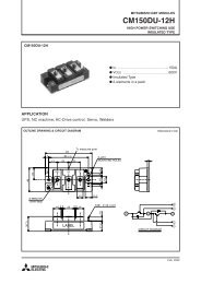
CYLINDRICAL TRACTION CAPACITORS<br />
The dedicated retrofit for SIEMENS B25353<br />
The <strong>capacitors</strong> of our SR17 series were developed especially for the maintenance<br />
of older traction converters manufactured in the 1970s…1990s. By<br />
consequent development of our well-proven MKP-technologies, we managed<br />
to place self-healing DC-<strong>capacitors</strong> <strong>with</strong> very high energy density and stability<br />
of capacitance into can dimensions smaller than, or identical to, those of<br />
the traditional MP-<strong>capacitors</strong> (SIEMENS/EPCOS codes B25353), which makes<br />
them ideal drop-in replacements for maintenance and retrofit programs.<br />
Moreover, the low-loss polypropylene dielectric and the <strong>large</strong> safety margins<br />
permit a far higher AC ripple load than available <strong>with</strong> the conventional<br />
MP-<strong>capacitors</strong>.<br />
Our SR17 are housed in a hermetical stainless steel cylinder. As opposed<br />
to the oil-filled MP-models, these are filled <strong>with</strong> an eco-friendly solid resin<br />
which not only makes them safe against leakage of liquids but also insensitive<br />
to the shocks and vibrations common in traction applications. The same<br />
applies to their robust plastic insulators.<br />
As a result, the SR17 TM is not just new, but far more reliable, durable and less<br />
sensitive than the capacitor it replaces.<br />
ZYLINDRISCHE BAHNKONDENSATOREN<br />
Der passende Ersatz für SIEMENS B25353<br />
Die Kondensatoren unserer SR17 Serie wurden speziell für den Ersatzteilbedarf<br />
älterer Bahnumrichter aus den 1970er... 1990er Jahren entwickelt.<br />
Durch konsequente Weiterentwicklung bewährter MKP-Technologien können<br />
wir selbstheilende Gleichspannungskondensatoren mit sehr hoher Energiedichte<br />
und Kapazitätskonstanz in identische oder sogar geringere Gehäuseabmessungen<br />
platzieren als die traditionellen MP-Kondensatoren (SIEMENS/<br />
EPCOS Serie B25353), womit sie eine ideale Alternative für Instandhaltungsund<br />
Austauschvorhaben darstellen. Durch das verlustarme Polypropylen<br />
Dielektrikum und die überaus großzügige Auslegung ist darüber hinaus eine<br />
wesentlich höhere Wechselspannungsbelastung als bei konventionellen<br />
MP-Kondensatoren möglich.<br />
Die SR17 sind in hermetisch dichten rostfreien Stahlzylindern untergebracht.<br />
Im Gegensatz zu den ölgefüllten MP-Modellen sind sie mit umweltfreundlichem<br />
ausgehärteten Harz vergossen und dadurch nicht nur<br />
auslaufsicher, sondern auch unempfindlich gegen bahntypische Stöße und<br />
Vibrationen.<br />
Dies gilt auch für die robusten Kunststoffisolatoren. Die SR17 sind folglich<br />
nicht nur neu, sondern auch zuverlässiger, unempfindlicher und langlebiger<br />
als der Kondensator, den sie ersetzen.<br />
DATA CHARTS_DATENTABELLEN_E50.U**_SR17 TM<br />
11
E50.U** SR17 TM<br />
DC/AC<br />
800...2650V<br />
SR17 TM DC <strong>capacitors</strong> for Traction Applications<br />
SR17 TM Gleichspannungskondensatoren für Traktionsanwendungen<br />
HIGH<br />
HIGH<br />
Standards IEC 61071<br />
optional 61881<br />
C N<br />
tolerance Toleranz ±10 / ±5<br />
tanδ 0 2 x10 -4<br />
can Gehäuse<br />
mounting position Einbaulage<br />
filling material Füllmittel<br />
internal protection<br />
Interne Sicherung<br />
fire load Brandlast<br />
stainless steel <strong>with</strong> welded lid<br />
Edelstahl, eingeschweißter Deckel<br />
optional beliebig<br />
no liquids (PUR, non-PCB) kein flüssiger<br />
Füllstoff, PUR-Harz (PCB-frei)<br />
none<br />
keine<br />
35 MJ/kg<br />
operating temperatures Grenztemperaturen<br />
Θ min ... Θ max<br />
-40 ... +70°C<br />
(short term load_Kurzbelastung: 85°C)<br />
Θ HOTSPOT < 70°C<br />
storing temperature Lagertemperatur<br />
Failure rate Ausfallrate<br />
reference service period_Referenzbetriebsdauer 150000 h, Θ HOTSPOT 70°<br />
-40 ... +85°C<br />
50 FIT<br />
DATA CHARTS_DATENTABELLEN_E50.U**_SR17 TM<br />
F<br />
U N<br />
DC C N<br />
U r<br />
U S<br />
U BB<br />
U BG<br />
R th<br />
I max<br />
Î I S<br />
W N<br />
R S<br />
L e<br />
D 1<br />
× L 1<br />
m order no.<br />
(V) (µF) (V) (V) (DC/10s) (AC/10s) (K/W) (A) (kA) (kA) (Ws) (mΩ) (nH) (mm) (kg) Bestell-Nr.<br />
800 1650 200 1200 1200 3000 0.67 200 25 75 528 0.4 120 142 × 465 8 E50.T47-165F50<br />
1200 1300 300 1800 1800 6000 0.50 200 19 57 936 0.4 120 172 × 518 14 E50.U52-135F50<br />
1800 757 300 2700 2700 10000 0.40 200 30 90 1226 0.38 120 172 × 650 17 E50.U65-764F50<br />
2200 770 560 3300 3300 6000 0.32 200 26 80 1863 0.35 120 172 × 800 21 E50.U80-774F50<br />
2400 280 560 3600 3600 6000 0.50 200 17 51 806 0.3 120 172 × 518 14 E50.U52-284F50<br />
2650 457 450 4000 3975 11000 0.40 120 25 150 1605 0.5 75 172 × 650 17 E50.U65-464F30<br />
2650 630 450 4000 3975 11000 0.40 120 34 200 2212 0.4 100 172 × 650 17 E50.U65-634F30<br />
U N<br />
AC C N<br />
U rms<br />
U S<br />
U BB<br />
U BG<br />
R th<br />
I max<br />
Î I S<br />
W N<br />
R S<br />
L e<br />
D 1<br />
× L 1<br />
m order no.<br />
(V) (µF) (V) (V) (DC/10s) (AC/10s) (K/W) (A) (kA) (kA) (Ws) (mΩ) (nH) (mm) (kg) Bestell-Nr.<br />
1700 80 1250 2700 3810 5000 0.60 100 13.8 41.4 125 0.4 120 142 × 518 8 E50.T52-803F50 1<br />
1<br />
100 FIT<br />
12
F<br />
F<br />
Design F<br />
40 d<br />
ø 13<br />
L 1<br />
L 2<br />
L a<br />
30<br />
CAPACITORS WITH A CAN DIAMETER OF 142 and 172 mm<br />
Can material<br />
stainless steel <strong>with</strong> welded lid<br />
Terminal torque<br />
F3 (M12)<br />
14 Nm<br />
F5 (M16)<br />
25 Nm<br />
I max (Terminals)<br />
M12<br />
80 A<br />
M16<br />
200 A<br />
Degree of protection IP 00<br />
K<br />
43 mm<br />
L<br />
30 mm<br />
Humidity class<br />
C<br />
KONDENSATOREN MIT GEHÄUSEDURCHMESSER 142 und 172 mm<br />
D 1<br />
Gehäusematerial<br />
Edelstahl, eingeschweißter Deckel<br />
Anschlußdrehmoment<br />
F3 (M12)<br />
14 Nm<br />
F5 (M16)<br />
25 Nm<br />
I max (Anschlüsse)<br />
M12<br />
80 A<br />
M16<br />
200 A<br />
Schutzgrad IP 00<br />
K<br />
43 mm<br />
L<br />
30 mm<br />
Feuchteklasse<br />
C<br />
bracket 95°<br />
Winkel 95° 40<br />
2<br />
a<br />
63<br />
D 1<br />
L 1<br />
L 2<br />
(±3) L a<br />
(±3) d a (±2)<br />
172.5 450 ± 2 100 70 M16 100<br />
172.5 520 + 3/-10 100 70 M16 100<br />
172.5 650 + 3/-10 90 55 M12 100<br />
172.5 800 + 3/-10 100 70 M16 100<br />
142.0 465 + 3/-10 100 70 M16 60<br />
142.0 518 + 3/-10 100 70 M16 60<br />
DIMENSIONAL DRAWINGS_MASSZEICHNUNGEN_F<br />
13
Important Remarks<br />
Failure Rate<br />
The failure probability of a component is a statistical value which is described<br />
by a log-normal distribution:<br />
Wichtige Hinweise<br />
Ausfallrate<br />
Die Ausfallwahrscheinlichkeit eines Bauelements ist eine statistische Größe,<br />
die mit Hilfe einer Normalverteilung beschrieben wird. Es gilt:<br />
N = N o × e¯λt<br />
N = number of functional components after period t<br />
Anzahl der nach der Zeit t intakten Bauelemente<br />
N o = total number of components at time t = 0<br />
Gesamtzahl der Bauelemente zum Zeitpunkt t = 0<br />
λ = failure rate Ausfallrate<br />
λ is the failure rate, which alternatively is also stated as the so-called FITrate<br />
(FIT = Failures In Time = λ x 10 9 ).<br />
The failure rate is very closely linked <strong>with</strong> operating temperature and operating<br />
voltage of the capacitor. The FIT rates stated in this catalogue are related<br />
to the <strong>capacitors</strong>’ rated voltage and a dielectric temperature (= HOTSPOT<br />
temperature) of 70°C.<br />
The simultaneous operation of <strong>capacitors</strong> at highest permissible voltage and<br />
operating temperature should be avoided; otherwise, failure rates may increase<br />
beyond reasonable technical reliability.<br />
The standard reference period for the failure rate statement is 100.000<br />
hours.<br />
Please note that FIT rates can be altered or improved by technical adjustments.<br />
Please contact us for details.<br />
Dabei ist λ die Ausfallrate, die alternativ auch als FIT –Rate angegeben wird<br />
(FIT = λ x 10 9 )<br />
Die Ausfallrate ist stark abhängig von der Temperatur und der Betriebsfeldstärke.<br />
Die FIT-Raten im Katalogsortiment beziehen sich auf 70°C<br />
Dielektrikumstemperatur (=Hotspot-Temperatur) und die Nennspannung des<br />
Kondensators.<br />
Der Betrieb von Kondensatoren mit der höchsten zulässigen Spannung und<br />
der höchsten zulässigen Betriebstemperatur sollte vermieden werden, andernfalls<br />
können die Ausfallraten so hoch werden, dass keine technisch<br />
sinnvollen Zuverlässigkeiten mehr gewährleistet sind.<br />
Der Wert für die Ausfallrate bezieht sich auf einen Referenzzeitraum von<br />
100.000h.<br />
Bitte beachten Sie, daß FIT-Raten durch technische Anpassung der Kondensatoren<br />
beeinflußt und verbessert werden können. Auskünfte hierzu erteilen<br />
wir auf Anfrage.<br />
The following diagram demonstrates the correlation between FIT rate, operating<br />
voltages and operating temperatures.<br />
Das nachstehende Kurvendiagramm macht den Zusammenhang von FIT-Rate,<br />
Betriebsspannung und Betriebstemperatur deutlich.<br />
ANNEX_ANHANG<br />
14
10000<br />
FIT 85°C<br />
Θ HOTSPOT<br />
50 FIT<br />
1000<br />
80°C<br />
100<br />
75°C<br />
70°C<br />
65°C<br />
60°C<br />
55°C<br />
10<br />
1<br />
0<br />
0.6 × U N<br />
0.7 × U N<br />
0.8 × U N<br />
0.9 × U N<br />
1.0 × U N<br />
1.1 × U N<br />
1.2 × U N<br />
300 FIT<br />
10000<br />
FIT<br />
85°C 80°C<br />
75°C<br />
Θ HOTSPOT<br />
1000<br />
70°C<br />
65°C<br />
60°C<br />
55°C<br />
100<br />
10<br />
1<br />
0<br />
0.6 × U N 0.7 × U N 0.8 × U N 0.9 × U N 1.0 × U N 1.1 × U N 1.2 × U N<br />
ANNEX_ANHANG<br />
15
Safety<br />
ELECTRONICON will not indemnify or be responsible for any kind of damages<br />
to persons or property due to the improper application of any <strong>capacitors</strong> purchased<br />
from ELECTRONICON or its distributors.<br />
The <strong>capacitors</strong> should only be used for the application intended.<br />
Mind that electrical or mechanical misapplication of <strong>capacitors</strong> can become<br />
hazardous. Misapplied <strong>capacitors</strong> can explode or catch fire and cause bodily<br />
injury or property damage due to the expulsion of material or metal fragments.<br />
Please consult the detailed instructions for mounting and application stated<br />
in our brochure „Application Notes“ and on the ELECTRONICON website.<br />
If in doubt about how to connect, operate, or discharge a capacitor, consult<br />
ELECTRONICON engineering.<br />
Mounting And Cooling<br />
The useful life of a capacitor may be reduced dramatically if exposed to<br />
excessive heat. Typically an increase in the ambient temperature of 7°C will<br />
halve the expected life of the capacitor. Make sure to obey the permitted<br />
operating temperatures.<br />
To avoid overheating the <strong>capacitors</strong> must be allowed to cool unhindered and<br />
should be shielded from external heat sources. We recommend forced ventilation<br />
for all applications <strong>with</strong> detuning reactors.<br />
Give at least 20mm clearance between the <strong>capacitors</strong> for natural or forced<br />
ventilation, and do not place them directly above or next to heat sources such<br />
as detuning or tuning reactors, bus bars, etc.<br />
Sicherheit<br />
ELECTRONICON übernimmt keine Verantwortung oder Haftung für jegliche<br />
Schäden an Personen oder Eigentum, welche aus der unsachgemäßen Anwendung<br />
von bei ELECTRONICON oder seinen Distributoren erworbenen Kondensatoren<br />
herrührt.<br />
Die Kondensatoren dürfen ausschließlich für ihren Bestimmungszweck verwendet<br />
werden.<br />
Beachten Sie, daß ein elektrisch oder mechanisch fehlerhafter Einsatz von<br />
Kondensatoren gefährlich sein kann. Falsch eingesetzte Kondensatoren können<br />
explodieren oder Feuer fangen und infolge austretender Materialien bzw.<br />
Metallteile gesundheitliche und materielle Schäden verursachen.<br />
Bitte konsultieren Sie die detaillierten Anweisungen in unserer Broschüre<br />
„Anwendungshinweise” sowie auf der Webseite von ELECTRONICON.<br />
Bitte konsultieren Sie das Fachpersonal von ELECTRONICON oder seiner<br />
Distributoren bei allen Fragen bezüglich des Anschlusses, der Verwendung<br />
oder der Entladung von Kondensatoren.<br />
Montage und Kühlung<br />
Die Lebensdauer eines Kondensators kann durch übermäßige Wärmeeinwirkung<br />
erheblich verringert werden. Im allgemeinen führt eine Erhöhung der<br />
Umgebungstemperatur um 7°C zu einer Verringerung der Lebensdauer des<br />
Kondensators um 50 %. Halten Sie die zugelassenen Betriebstemperaturen<br />
ein.<br />
Um Überhitzung zu vermeiden, muß gewährleistet sein, daß die Kondensatoren<br />
auftretende Verlustwärme ungehindert abführen können und vor fremden<br />
Wärmequellen abgeschirmt werden. Insbesondere bei verdrosselten Anlagen<br />
ist in jedem Falle eine Zwangslüftung zu empfehlen. Zwischen den und um<br />
die Kondensatoren herum sollten mindenstens 20mm Platz für natürliche<br />
oder Zwangslüftung belassen werden. Bringen Sie den Kondensator nie direkt<br />
neben oder über Wärmequellen, wie Drosseln u. ä. an.<br />
ANNEX_ANHANG<br />
Protection against Overvoltages And Short Circuits:<br />
Self-Healing Dielectric<br />
All dielectric structures used in our power <strong>capacitors</strong> are „selfhealing“: In the<br />
event of a voltage breakdown the metal layers around the breakdown channel<br />
are evaporated by the temperature of the electric arc that forms between the<br />
electrodes. They are removed <strong>with</strong>in a few microseconds and pushed apart by<br />
the pressure generated in the centre of the breakdown spot.<br />
An insulation area is formed which is reliably resistive and voltage proof for<br />
all operating requirements of the capacitor. The capacitor remains fully functional<br />
during and after the breakdown.<br />
For voltages <strong>with</strong>in the permitted testing and operating limits the <strong>capacitors</strong><br />
are short-circuit- and overvoltage-proof. They are also proof against external<br />
short circuits as far as the resulting surge discharges do not exceed the<br />
specified surge current limits.<br />
Schutz gegen Überspannungen und Kurzschlüsse: Selbstheilendes<br />
Dielektrikum<br />
Alle in unseren Leistungskondensatoren eingesetzten dielektrischen Strukturen<br />
sind selbstheilend. Im Falle eines Kurzschlusses (Spannungsdurchschlag)<br />
verdampfen die Metallbeläge um den Durchschlagspunkt herum<br />
aufgrund der Temperatur des Lichtbogens, der sich zwischen den Elektroden<br />
bildet. Innerhalb weniger Mikrosekunden wird der Metalldampf durch den<br />
beim Durchschlag entstehenden Überdruck vom Zentrum des Durchschlages<br />
weggedrückt. Aus diese Weise bildet sich eine belagfreie Zone rings um den<br />
Durchschlagspunkt, wodurch dieser vollständig isoliert wird. Der Kondensator<br />
bleibt während und nach dem Durchschlag voll funktionsfähig.<br />
Für Spannungen innerhalb der zugelassenen Test- und Betriebsbedingungen<br />
sind die Kondensatoren kurzschluss- und überspannungssicher. Sie sind<br />
außerdem sicher gegen äußere Kurzschlüsse, sofern bei den dabei entstehenden<br />
Stoßentladungen die zugelassenen Stoßströme nicht überschritten<br />
werden.<br />
16
3 Year Limited Warranty<br />
All our products are designed, manufactured, and tested <strong>with</strong> the highest<br />
care and workmanship. The satisfaction of our customers is our highest goal.<br />
We therefore warrant remedying any defect in the goods resulting from faulty<br />
design, materials or workmanship, which appears <strong>with</strong>in 3 years from the<br />
date of sale.<br />
This warranty does not cover defects due to improper use of the goods or<br />
operation at conditions exceeding the rated values stated in the catalogue<br />
or special data sheet. Nor does it cover defects due to faulty maintenance or<br />
incorrect installation, alterations or faulty repairs undertaken by the Buyer.<br />
Finally the warranty does not cover normal wear and tear or deterioration.<br />
See our „General Conditions“ for details on Warranty and Product liability.<br />
Find more information and detailed instructions in our „Application Notes”<br />
and on www.electronicon.com<br />
3 Jahre Gewährleistung<br />
Alle unsere Erzeugnisse werden mit höchster Sorgfalt und Fachkenntnis entwickelt,<br />
hergestellt und geprüft. Die Zufriedenheit unserer Kunden ist unser<br />
höchstes Ziel. Wir verpflichten uns daher, jeden innerhalb von 3 Jahren ab<br />
Verkaufsdatum auftretenden Mangel an unseren Erzeugnissen zu beseitigen,<br />
welcher aus Fehlern in Design, Material oder Herstellung herrührt.<br />
Diese Gewährleistung erstreckt sich nicht auf Defekte, welche auf unsachgemäße<br />
Anwendung oder Betrieb jenseits der nach Katalog oder speziellem<br />
Datenblatt zulässigen Einsatzbedingungen zurückzuführen sind. Sie erfaßt<br />
ebensowenig Schäden, welche aus fehlerhafter Wartung, unsachgemäßer<br />
Montage, Änderungen oder unsachgemäßen Reparaturen durch den Käufer<br />
bzw. Anwender resultieren. Schließlich betrifft diese Gewährleistung auch<br />
nicht normale Abnutzung und Verschleiß.<br />
Siehe unsere „Allgemeinen Geschäftsbedingungen” für Details zu Gewährleistung<br />
und Produkthaftung.<br />
Mehr Informationen und ausführliche Anweisungen finden Sie in unseren<br />
„Anwendungshinweisen“ und unter www.electronicon.com<br />
ANNEX_ANHANG<br />
17