Logamax plus GB162 - Buderus
Logamax plus GB162 - Buderus
Logamax plus GB162 - Buderus

Erfolgreiche ePaper selbst erstellen
Machen Sie aus Ihren PDF Publikationen ein blätterbares Flipbook mit unserer einzigartigen Google optimierten e-Paper Software.
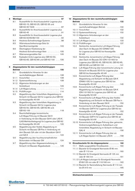
Inhaltsverzeichnis<br />
8 Montage . . . . . . . . . . . . . . . . . . . . . . . . . . . . . . . . . . . . 87<br />
8.1 Auswahlhilfe für Anschlusszubehör <strong>Logamax</strong> <strong>plus</strong><br />
<strong>GB162</strong>-15, <strong>GB162</strong>-25, <strong>GB162</strong>-35 und<br />
<strong>GB162</strong>-25 T40S . . . . . . . . . . . . . . . . . . . . . . . . . 87<br />
8.2 Auswahlhilfe für Anschlusszubehör <strong>Logamax</strong> <strong>plus</strong><br />
<strong>GB162</strong>-45 . . . . . . . . . . . . . . . . . . . . . . . . . . . . . . 91<br />
8.3 Auswahlhilfe für Anschlusszubehör <strong>Logamax</strong> <strong>plus</strong><br />
<strong>GB162</strong>-50/65/80/100 . . . . . . . . . . . . . . . . . . . . 94<br />
8.4 Heizkreis-Schnellmontage-Systeme . . . . . . . . . . 98<br />
8.5 Wärmetauscherkennungs-Sets für<br />
Gas-Brennwertgeräte . . . . . . . . . . . . . . . . . . . . 103<br />
8.6 Übertragbare Heizleistung der<br />
Heizkreis-Schnellmontage-Sets . . . . . . . . . . . . 105<br />
8.7 Wärmemengenzähler-Set . . . . . . . . . . . . . . . . 105<br />
8.8 Kaskaden-Units <strong>Logamax</strong> <strong>plus</strong> <strong>GB162</strong>-50,<br />
<strong>GB162</strong>-65, <strong>GB162</strong>-80 und <strong>GB162</strong>-100 . . . . 106<br />
9 Abgassysteme für den raumluftabhängigen<br />
Betrieb . . . . . . . . . . . . . . . . . . . . . . . . . . . . . . . . . . . . .108<br />
9.1 Grundsätzliche Hinweise für den<br />
raumluftabhängigen Betrieb . . . . . . . . . . . . . . . 108<br />
9.1.1 Vorschriften . . . . . . . . . . . . . . . . . . . . . . . . . . . . 108<br />
9.1.2 Systemzertifizierung . . . . . . . . . . . . . . . . . . . . . 108<br />
9.1.3 Allgemeine Anforderungen an den<br />
Aufstellraum . . . . . . . . . . . . . . . . . . . . . . . . . . . . 109<br />
9.1.4 Luft-Abgas-Leitung . . . . . . . . . . . . . . . . . . . . . . 111<br />
9.1.5 Prüföffnungen . . . . . . . . . . . . . . . . . . . . . . . . . . 114<br />
9.2 Abgasführung über hinterlüftete Abgasleitung im<br />
Schacht mit Bausatz GA für <strong>Logamax</strong> <strong>plus</strong> <strong>GB162</strong><br />
bis Kesselgröße 45 kW . . . . . . . . . . . . . . . . . . 116<br />
9.3 Abgasführung über hinterlüftete Abgasleitung im<br />
Schacht mit Bausatz GA für <strong>Logamax</strong> <strong>plus</strong><br />
<strong>GB162</strong>-50, <strong>GB162</strong>-65, <strong>GB162</strong>-80 und<br />
<strong>GB162</strong>-100 . . . . . . . . . . . . . . . . . . . . . . . . . . . . 118<br />
9.4 Raumluftabhängige konzentrische<br />
Luft-Abgas-Führung mit Bausatz GA-X<br />
in Verbindung mit dem Bausatz GA-K oder LAS-K<br />
(LAS-Mehrfachbelegung) für <strong>Logamax</strong> <strong>plus</strong> <strong>GB162</strong><br />
bis Kesselgröße 35 kW . . . . . . . . . . . . . . . . . . 120<br />
9.5 Abgasführung über flexible Abgasleitung im<br />
Schacht mit Bausatz ÜB-Flex in Verbindung mit<br />
dem Bausatz GA oder mit den Bausätzen GA-X<br />
und GA-K . . . . . . . . . . . . . . . . . . . . . . . . . . . . . . 122<br />
9.6 Abgasführung über feuchteunempfindlichen<br />
Schornstein mit Bausatz GN . . . . . . . . . . . . . . 124<br />
9.7 Abgasführung über Abgassammelleitung im<br />
Schacht mit Bausatz Abgaskaskade . . . . . . . . 126<br />
10 Abgassysteme für den raumluftunabhängigen<br />
Betrieb . . . . . . . . . . . . . . . . . . . . . . . . . . . . . . . . . . . . 132<br />
10.1 Grundsätzliche Hinweise für den<br />
raumluftunabhängigen Betrieb . . . . . . . . . . . . .132<br />
10.1.1 Vorschriften . . . . . . . . . . . . . . . . . . . . . . . . . . . . 132<br />
10.1.2 Systemzertifizierung . . . . . . . . . . . . . . . . . . . . . 132<br />
10.1.3 Allgemeine Anforderungen an den<br />
Aufstellraum . . . . . . . . . . . . . . . . . . . . . . . . . . . .132<br />
10.1.4 Luft-Abgas-Leitung . . . . . . . . . . . . . . . . . . . . . . 133<br />
10.1.5 Prüföffnungen . . . . . . . . . . . . . . . . . . . . . . . . . . 137<br />
10.2 Senkrechte, konzentrische Luft-Abgas-Führung<br />
über Dach mit Bausatz DO (DN80/125)<br />
für <strong>Logamax</strong> <strong>plus</strong> <strong>GB162</strong> bis Kesselgröße<br />
50 kW . . . . . . . . . . . . . . . . . . . . . . . . . . . . . . . . .138<br />
10.3 Senkrechte, konzentrische Luft-Abgas-Führung<br />
über Dach mit Bausatz DO (DN110/160) für<br />
<strong>Logamax</strong> <strong>plus</strong> <strong>GB162</strong>-45, <strong>GB162</strong>-50, <strong>GB162</strong>-65,<br />
<strong>GB162</strong>-80 und <strong>GB162</strong>-100 . . . . . . . . . . . . . . .141<br />
10.4 Luft-Abgas-Führung über konzentrische Leitung im<br />
Schacht mit Bausatz DO-S für <strong>Logamax</strong> <strong>plus</strong><br />
<strong>GB162</strong> bis Kesselgröße 45 kW . . . . . . . . . . . .144<br />
10.5 Konzentrische Luft-Abgas-Führung über<br />
Abgasleitung und Schacht mit Bausatz GA-K<br />
(DN80/125) für <strong>Logamax</strong> <strong>plus</strong> <strong>GB162</strong> bis<br />
Kesselgröße 45 kW . . . . . . . . . . . . . . . . . . . . . .146<br />
10.6 Konzentrische Luft-Abgas-Führung über<br />
Abgasleitung und Schacht mit Bausatz GA-K<br />
(DN110/160) für <strong>Logamax</strong> <strong>plus</strong> <strong>GB162</strong> ab<br />
Kesselgröße 50 kW . . . . . . . . . . . . . . . . . . . . . .148<br />
10.7 Konzentrische Luft-Abgas-Führung über flexible<br />
Abgasleitung und Schacht mit Bausatz ÜB-Flex in<br />
Verbindung mit dem Bausatz GA-K . . . . . . . . .150<br />
10.8 Konzentrische Luft-Abgas-Führung an der Fassade<br />
mit Bausatz GAF-K für <strong>Logamax</strong> <strong>plus</strong> <strong>GB162</strong> bis<br />
Kesselgröße 45 kW . . . . . . . . . . . . . . . . . . . . . .152<br />
10.9 Konzentrische Luft-Abgas-Führung an der Fassade<br />
mit Bausatz GAF-K für <strong>Logamax</strong> <strong>plus</strong> <strong>GB162</strong> ab<br />
Kesselgröße 50 kW . . . . . . . . . . . . . . . . . . . . . .154<br />
10.10 Konzentrische Luft-Abgas-Führung über getrennte<br />
Verbrennungsluftleitung im Aufstellraum und<br />
hinterlüftete Abgasleitung im Schacht mit Bausatz<br />
GAL-K . . . . . . . . . . . . . . . . . . . . . . . . . . . . . . . . .156<br />
10.11 Konzentrische Luft-Abgas-Führung über ein<br />
Luft-Abgas-System mit Bausatz LAS-K . . . . . .158<br />
11 Einzelbauteile für die Abgassysteme . . . . . . . . . 160<br />
11.1 Maße ausgewählter Einzelbauteile . . . . . . . . . . 160<br />
11.1.1 Bauteile für Einzelgerät Nennweite Ø 80 mm<br />
oder Ø 110 mm . . . . . . . . . . . . . . . . . . . . . . . . .160<br />
11.1.2 Bauteile für Einzelgerät Nennweite Ø 125 mm<br />
oder Ø 160 mm . . . . . . . . . . . . . . . . . . . . . . . . .161<br />
11.1.3 Luft-Abgas-Leitungen für Einzelgerät Nennweite<br />
Ø 80/125 mm oder Ø 110/160 mm . . . . . . . .162<br />
11.1.4 Bauteile für Sammelleitung Nennweite Ø 110 mm<br />
bis Ø 315 mm . . . . . . . . . . . . . . . . . . . . . . . . . .165<br />
Stichwortverzeichnis . . . . . . . . . . . . . . . . . . . . . . . 167<br />
4<br />
6 720 642 463 (07/2010) – Planungsunterlage Gas-Brennwertgerät <strong>Logamax</strong> <strong>plus</strong> <strong>GB162</strong>