KURZANLEITUNG FRENIC Multi LM1 - Welcome to Fuji Electric
KURZANLEITUNG FRENIC Multi LM1 - Welcome to Fuji Electric
KURZANLEITUNG FRENIC Multi LM1 - Welcome to Fuji Electric

Erfolgreiche ePaper selbst erstellen
Machen Sie aus Ihren PDF Publikationen ein blätterbares Flipbook mit unserer einzigartigen Google optimierten e-Paper Software.
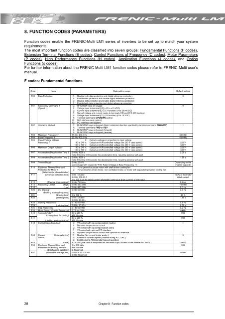
8. FUNCTION CODES (PARAMETERS)<br />
Function codes enable the <strong>FRENIC</strong>-<strong>Multi</strong> <strong>LM1</strong> series of inverters <strong>to</strong> be set up <strong>to</strong> match your system<br />
requirements.<br />
The most important function codes are classified in<strong>to</strong> seven groups: Fundamental Functions (F codes),<br />
Extension Terminal Functions (E codes), Control Functions of Frequency (C codes), Mo<strong>to</strong>r Parameters<br />
(P codes), High Performance Functions (H codes), Application Functions (J codes), and Option<br />
Functions (o codes).<br />
For further information about the <strong>FRENIC</strong>-<strong>Multi</strong> <strong>LM1</strong> function codes please refer <strong>to</strong> <strong>FRENIC</strong>-<strong>Multi</strong> user's<br />
manual.<br />
F codes: Fundamental functions<br />
28<br />
Code Name Data setting range Default setting<br />
F00 Data Protection<br />
0: Disable both data protection and digital reference protection 0<br />
1: Enable data protection and disable digital reference protection<br />
2: Disable data protection and enable digital reference protection<br />
3: Enable both data protection and digital reference protection<br />
F01 Frequency Command 1<br />
0: UP/DOWN keys on keypad 0<br />
(Speed 1)<br />
1: Voltage input <strong>to</strong> terminal [12] (-10 <strong>to</strong> +10 VDC)<br />
2: Current input <strong>to</strong> terminal [C1] (C1 function) (4 <strong>to</strong> 20 mA DC)<br />
3: Sum of voltage and current inputs <strong>to</strong> terminals [12] and [C1] (C1 function)<br />
5: Voltage input <strong>to</strong> terminal [C1] (V2 function) (0 <strong>to</strong> 10 VDC)<br />
7: Terminal command UP/DOWN control<br />
11: DIO interface card (option)<br />
12: PG interface card (option)<br />
F02 Operation Method<br />
0: RUN/STOP keys on keypad (Mo<strong>to</strong>r rotational direction specified by terminal command FWD/REV) 1<br />
1: Terminal command FWD or REV<br />
2: RUN/STOP keys on keypad (forward)<br />
3: RUN/STOP keys on keypad (reverse)<br />
F03 Maximum Frequency 1 25.0 <strong>to</strong> 400.0 Hz 50.0 Hz<br />
F04 Base Frequency 1 25.0 <strong>to</strong> 400.0 Hz 50.0 Hz<br />
F05 Rated Voltage at Base<br />
0: Output a voltage in proportion <strong>to</strong> input voltage<br />
Frequency 1<br />
80 <strong>to</strong> 240 V: Output an AVR-controlled voltage (for 200 V class series) 220 V<br />
160 <strong>to</strong> 500 V: Output an AVR-controlled voltage (for 400 V class series) 380 V<br />
F06 Maximum Output Voltage 1<br />
80 <strong>to</strong> 240 V: Output an AVR-controlled voltage (for 200 V class series) 220 V<br />
160 <strong>to</strong> 500 V: Output an AVR-controlled voltage (for 400 V class series) 380 V<br />
F07 Acceleration/Deceleration Time 1 0.00 <strong>to</strong> 3600 s<br />
Note: Entering 0.00 cancels the acceleration time, requiring external soft-start.<br />
2.00 s<br />
F08 Acceleration/Deceleration Time 2 0.00 <strong>to</strong> 3600 s 1.80 s<br />
F09 Torque Boost 1<br />
Note: Entering 0.00 cancels the deceleration time, requiring external soft-start.<br />
0.0 <strong>to</strong> 20.0 %<br />
Depending on the<br />
(percentage with respect <strong>to</strong> "F05: Rated Voltage at Base Frequency 1")<br />
inverter capacity<br />
F10 Electronic Thermal Overload 1: For a general-purpose mo<strong>to</strong>r with shaft-driven cooling fan 1<br />
Protection for Mo<strong>to</strong>r 1<br />
(Select mo<strong>to</strong>r characteristics)<br />
2: For an inverter-driven mo<strong>to</strong>r, non-ventilated mo<strong>to</strong>r, or mo<strong>to</strong>r with separately powered cooling fan<br />
F11 (Overload detection level) 0.00: Disable<br />
100% of the mo<strong>to</strong>r<br />
0.01 <strong>to</strong> 100.00 A<br />
1 <strong>to</strong> 135 % of the rated current (allowable continuous drive current) of the mo<strong>to</strong>r<br />
rated current<br />
F12 (Thermal time constant) 0.5 <strong>to</strong> 75.0 min 5.0min<br />
F15 Frequency Limiter (High) 0.0 <strong>to</strong> 400.0 Hz 70.0 Hz<br />
F16 (Low) 0.0 <strong>to</strong> 400.0 Hz 0.0 Hz<br />
F20 DC Braking 1 0.0 <strong>to</strong> 60.0 Hz 0.5 Hz<br />
F21<br />
(Braking starting frequency)<br />
(Braking level) 0 <strong>to</strong> 100 % 80 %<br />
F22 (Braking time) 0.00 : Disable<br />
0.01 <strong>to</strong> 30.00 s<br />
1.50 s<br />
F23 Starting Frequency 1 0.1 <strong>to</strong> 60.0 Hz 0.5 Hz<br />
F24 (Holding time) 0.00 <strong>to</strong> 10.00 s 0.80 s<br />
F25 S<strong>to</strong>p Frequency 0.1 <strong>to</strong> 60.0 Hz 0.2 Hz<br />
F26 Mo<strong>to</strong>r Sound (Carrier frequency) 0.75 <strong>to</strong> 15 Hz 8 kHz<br />
F40 Torque Limiter 1<br />
20 <strong>to</strong> 200 %<br />
999<br />
(Limiting level for driving) 999: Disable<br />
F41<br />
20 <strong>to</strong> 200 %<br />
999<br />
(Limiting level for braking) 999: Disable<br />
F42 Control Mode Selection 1 0: V/f control with slip compensation inactive 1<br />
1: Dynamic <strong>to</strong>rque vec<strong>to</strong>r control<br />
2: V/f control with slip compensation active<br />
3: V/f control with optional PG interface<br />
4: Dynamic <strong>to</strong>rque vec<strong>to</strong>r control with optional PG interface<br />
F43 Current (Mode selection) 0: Disable (No current limiter works.) 0<br />
Limiter<br />
1: Enable at constant speed (Disable during ACC/DEC)<br />
2: Enable during ACC/constant speed operation<br />
F44<br />
(Level) 20 <strong>to</strong> 200 (The data is interpreted as the rated output current of the inverter for 100 %.) 200 %<br />
F50 Electronic Thermal Overload 1 <strong>to</strong> 900 kWs 999<br />
Protection for Braking Resis<strong>to</strong>r 999: Disable<br />
(Discharging capability) 0: Reserved<br />
F51 (Allowable average loss) 0.001 <strong>to</strong> 50.000 kW<br />
0.000: Reserved<br />
0.000<br />
Chapter 8: Function codes