Grundlagen Epoxydharze - Kap. 1 Arbeitsanleitungen
Grundlagen Epoxydharze - Kap. 1 Arbeitsanleitungen
Grundlagen Epoxydharze - Kap. 1 Arbeitsanleitungen

Erfolgreiche ePaper selbst erstellen
Machen Sie aus Ihren PDF Publikationen ein blätterbares Flipbook mit unserer einzigartigen Google optimierten e-Paper Software.
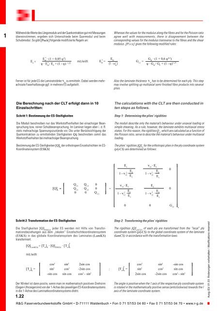
1Während die Werte des Längsmoduls und der Querkontraktion gut mit Messungenübereinstimmen, ergeben sich Unterschiede beim Quermodul und beimSchubmodul. So gibt [Puck] folgende modifizierte Regeln an:Whereas the values for the modulus along the fibres and for the Poisson ratioagree well with measurements, there is disagreement between thecorresponding values for the modulus transverse to the fibres and the shearmodulus. [PUCK] gives the following modified rules:*E H⋅ (1 + 0,85 ϕ 2 )E 2=* 1,25ϕ⋅ E H/ E F+ (1 - ϕ)mit/with:*E H EH =2(1 - υ H)G H⋅ (1 + 0,6 ϕ 0,5 )G 12=1,25ϕ ⋅ G H/ G F+ (1 - ϕ)Ferner ist für jede ES die Laminatstärke a t kzu ermitteln. Dabei werden mehrachsialeFaserhalbzeuge ggf. in mehrere ES aufgeteilt.Also the laminate thickness a t khas to be determined for each ply. This stepmay involve splitting up multiaxial semi-finished fibre products into severalplies.Die Berechnung nach der CLT erfolgt dann in 10Einzelschritten:Schritt 1: Bestimmung der ES-SteifigkeitenDie Moduli beschreiben nur das Werkstoffverhalten bei einachsiger Beanspruchungbzw. reiner Schubbeanspruchung. Im Laminat liegen aber i. d. R.stets mehrachsige Spannungszustände vor. Die unter Berücksichtigung derQuerkontraktion zu ermittelnden Steifigkeiten Qij beschreiben somit dasWerkstoffverhalten bei mehrachsiger Beanspruchung.Bestimmung der ES-Steifigkeiten [Q] kder orthotropen Einzelschichten im ES-Koordinatensystem (ESKS):The calculations with the CLT are then conducted inten steps as follows.Step 1: Determining the plies’ rigiditiesThe moduli describe only the material’s behaviour under uniaxial loading orsimple shearing. As a rule, however, the laminate exhibits multiaxial stressstates. For this reason, the rigidities Q ij, which are calculated as a function ofthe Poisson ratio, serve to describe the material’s behaviour under multiaxialloading.The plies’ rigidities [Q] kfor the orthotropic plies in the ply coordinate system(plyCS) are determined as follows:⎡ E 1ν 12⋅ E 20⎤E2 2 2E 1 - 2ν12 ⋅ 1 - ν 12⋅E1 E1⎡ Q 21Q 120 ⎤[Q] k= Q 21Q 220 =⎣ 0 0 Q 33⎦ν 12⋅ E 2E 20E2 2 2E1 - ν 212⋅ 1 - ν 12⋅E1 E1⎣ 0 0 G 12⎦kSchritt 2: Transformation der ES-SteifigkeitenDie Steifigkeiten [Q] ESKS,kjeder ES werden mit Hilfe von Transformationsbeziehungenaus dem „lokalen“ Einzelschichtkoordinatensystem(ESKS) in das globale Koordinatensystem des Laminates (LamKS)transformiert.[Q] LamKS,k= [T σ] k⋅ [Q] ESKS,k⋅ [T σ] kmit/with:⎡ cos 2 sin 2 2sin cos ⎤[T σ] k= sin 2 cos 2 -2sin cos⎣ -sin cos sin cos cos 2 - sin 2 ⎦Der Winkel ist dann positiv, wenn man im mathematisch positiven Drehsinn(Gegen-Uhrzeigersinn) von der 1-Achse des jeweiligen ES-Koordinatensystemsin die 1-Achse des Laminatkoordinatensystems dreht.1.22T;Step 2: Transforming the plies’ rigiditiesThe rigidities [Q] plyCS,kof each ply are transformed from the “local” plycoordinate system (plyCS) to the global coordinate system of the laminate(lamCS) in accordance with the transformation laws.⎡ cos 2 sin 2 -sin cos ⎤T[T σ] k= sin 2 cos 2 sin cos⎣ 2sin cos -2sin cos cos 2 - sin 2 ⎦The angle is positive when the 1 axis of the respective ply coordinate systemis rotated in the mathematically positive sense (anticlockwise) towards the laxis of the laminate coordinate system.R&G Faserverbundwerkstoffe GmbH • D-71111 Waldenbuch • Fon 0 71 57/53 04 60 • Fax 0 71 57/53 04 70 • www.r-g.deAusg./Ed. 01.03 Änderungen vorbehalten / Modifications reserved