Montage- und Reparaturanleitung SSB 32 - bei ELAFLEX
Montage- und Reparaturanleitung SSB 32 - bei ELAFLEX
Montage- und Reparaturanleitung SSB 32 - bei ELAFLEX
- Keine Tags gefunden...

Sie wollen auch ein ePaper? Erhöhen Sie die Reichweite Ihrer Titel.
YUMPU macht aus Druck-PDFs automatisch weboptimierte ePaper, die Google liebt.
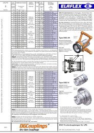
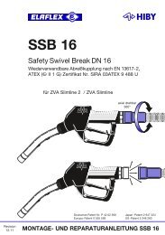
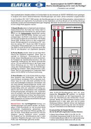
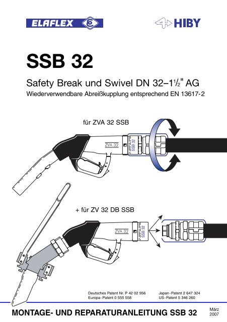
Zapfventil EO 317 <strong>SSB</strong> <strong>32</strong> Schlauchverschraubung BT <strong>32</strong>Der SAFETY SWIVEL BREAK "<strong>SSB</strong> <strong>32</strong>" ist eine selbstschließende Abreißkupplungmit Drehgelenk, die Zapfsäulen gegen Wegfahrunfälle schützen soll. Sie wirdzwischen dem ZVA <strong>32</strong> (oder ZV <strong>32</strong> DB mit Renk-Kupplung für Diesellok-Betankung, ohne Automatik) <strong>und</strong> der Schlauchleitung montiert. Jedes <strong>SSB</strong> <strong>32</strong> wirdvor Auslieferung entsprechend EN 13617-2 auf Abriss, Abdichtung <strong>und</strong> Prüfdruckstückgeprüft. Dies wird durch das Prüfzeichen, z.B. ••03 bestätigt. Bei einer Zugkraftzwischen 800 N -1500 N (~ 80 kg -150 kg) trennt sich die Kupplung, <strong>und</strong> zwar nichtnur <strong>bei</strong> axialer Überlastung, sondern auch <strong>bei</strong> Winkelbeanspruchungen bis zu ± 35°,wie sie in der Praxis besonders häufig vorkommen.ACHTUNG : Vor dem Einbau muss unbedingt geprüft werden, ob die Konstruktionder Zapfsäule <strong>und</strong> die Schlauchleitung eine Zugkraft von mehr als der maximalenmöglichen Trennkraft in allen Wegfahrrichtungen zulässt.Ein Dichtkegel im Ausreißteil stoppt den Kraftstofffluß der Schlauchseite. Nacheinem Abriss kann das <strong>SSB</strong> <strong>32</strong> gemäß nebenstehender Vorschrift von einemqualifizierten Monteur wieder zusammengesetzt, <strong>und</strong> nach vorgeschriebenerPrüfung erneut verwendet werden.MONTAGEHINWEISE• Zapfsäulenpumpe abstellen. Druck im Schlauch entlasten.• Zapfventil von der Schlauchleitung mit Hakenschlüssel EW - H 68/75 oderEW - GH 60/90 abschrauben <strong>und</strong> Schlauch entleeren.• Vorhandenes Drehgelenk (EA 318 / 318.4) vom Zapfventil abschrauben.• Gewinde des <strong>SSB</strong> <strong>32</strong> leicht einölen oder fetten <strong>und</strong> in das Zapfventil einschrauben.• BT <strong>32</strong> auf Schlauch ziehen (siehe Bild 1).• Gewinde des <strong>SSB</strong> <strong>32</strong> ölen oder fetten u. mit der Schlauchverschraubung verbinden.• BT <strong>32</strong> über <strong>SSB</strong> <strong>32</strong> schieben ( siehe Bild 2).• Pumpe anstellen <strong>und</strong> prüfen, ob alle Verbindungen dicht sind.Die untere Abbildung zeigt das montierte System.Die Break-Tülle BT <strong>32</strong> dient <strong>bei</strong> einer Trennung dem Schutz des Ausreißteils vorBeschädigungen.
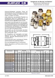
Gehäuse Dichtkegel EO 271 Ausreißteil Schlauchverschraubung MX <strong>32</strong> - 1 1 /2"WIEDERMONTAGE UND NEUEINSATZ NACH ABRISSACHTUNG: Diese Ar<strong>bei</strong>t darf nur von einem qualifizierten Monteur durchgeführtwerden. Er überprüft da<strong>bei</strong> auch Zapfsäule, Zapfventil <strong>und</strong> Schlauchleitungsanschlüsseauf mögliche Schäden <strong>und</strong> unterzieht das ganze System vorWiederinbetriebnahme einem Drucktest. Eine Wiedermontage direkt an derSchlauchleitung ist nicht möglich.Nachstehende <strong>Montage</strong>vorschriften müssen unbedingt beachtet werden:a) Zapfsäulenpumpe abstellen. Druck im Schlauch entlasten.b) Break-Tülle BT <strong>32</strong> über Schlauchverschraubung zurückschieben.c) <strong>SSB</strong>-Gehäuse vom Zapfventil <strong>und</strong> das Ausreißteil vom Schlauch abschrauben.Schlauch entleeren.d) Alle Teile säubern <strong>und</strong> auf mögliche <strong>bei</strong>m Unfall verursachte Schädenuntersuchen wie z.B. Ovalität oder andere Deformationen oder gebrocheneKunststoffteile. Bei solchen Schäden ist ein Wiedereinsatz nicht gestattet.Außer dem sichtbaren O-Ring sind keine Einzelteile lieferbar.e) Am Ausreißteil <strong>und</strong> Gehäuse alle metallischen Gleitflächen <strong>und</strong> die Nut für denSprengring sowie die O-Ringe dünn einfetten.f) Gehäuse in senkrechter Position halten <strong>und</strong> den Sprengring mit der Handzentrieren. Das Ausreißteil sorgfältig von oben in das Gehäuse einführen. Die<strong>bei</strong>den Kupplungshälften müssen zueinander zentrisch <strong>und</strong> unverkantetausgerichtet sein.g) Die Teile zentrisch zusammenhalten <strong>und</strong> mit der Kraft eines Schraubstockeszusammendrücken. Sicherstellen, daß die <strong>bei</strong>den Teile da<strong>bei</strong> axial geführtbleiben, bis sie hörbar <strong>und</strong> sichtbar zusammenschnappen.Danach das <strong>SSB</strong> <strong>32</strong> wieder zwischen Zapfventil <strong>und</strong>Schlauchleitung montieren, wie nebenstehendbeschrieben <strong>und</strong> prüfen, ob alles dicht ist.
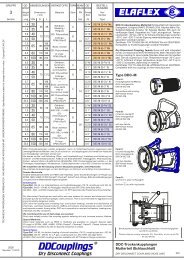
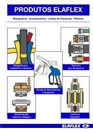
ZV <strong>32</strong> DB <strong>SSB</strong>Sonderausführung für dieDiesellok-Betankung derDeutschen Bahn.Gesamtgewicht = 5 kgBetriebsdruck = 0,5 bis 6 barMaximalleistungMediennicht geeignet für Wasser,Lösungsmittel= 200 l/min= Benzin, Diesel, Heizöl,Petroleum, Avgas<strong>und</strong> Jet - A1ACHTUNG!Keine automatische Abschaltung!Druckverlust ZV <strong>32</strong> DB <strong>SSB</strong>:Diesel / Heizöl EL<strong>bei</strong> RaumtemperaturG 1½Nächstgelegene ZVA-Servicefirma kann erfragt werden <strong>bei</strong>: <strong>ELAFLEX</strong> TankstellentechnikSchnackenburgallee 121 • 22525 Hamburg • Tel. (040) 540 00 50 • Fax (040) 540 00 567
<strong>SSB</strong> <strong>32</strong>Reusable Safety Break DN <strong>32</strong>–1 1 /2" AGcorresponding to EN 13617 - 2for ZVA <strong>32</strong> <strong>SSB</strong>+ for ZV <strong>32</strong> DB <strong>SSB</strong>German Patent No. P 42 02 956Europa-Patent 0 555 558Japan-Patent 2 647 <strong>32</strong>4US-Patent 5 346 260INSTALLATION AND REASSEMBLY GUIDE <strong>SSB</strong> <strong>32</strong>March2007
ody EO 317 <strong>SSB</strong> <strong>32</strong> hose fitting BT <strong>32</strong>The SAFETY SWIVEL BREAK "<strong>SSB</strong> <strong>32</strong>" is a self-sealing reusable break-awaycoupling designed to protect the pump against damage which can occur drive-offaccidents. As a nozzle break it is fitted between the ZVA <strong>32</strong> (or non-automaticZV <strong>32</strong> DB with "Renk" coupling for diesel locomotive refuelling) and the hoseassembly. Before delivery each <strong>SSB</strong> <strong>32</strong> is tested regarding the break-off andtightness <strong>und</strong>er pressure (acc. to standard EN 13617-2). This is documented bythe date code, e.g. ••03.When a pull off 800 N – 1500 N (~ 80 – 150 kg) is applied,either axially or at an angle up to ± 35° as quite often occurs in practice, thecoupling separates.WARNING : Before installation determine if the construction of the dispenser andthe pull resistance of the hose is suitable for a pull force higher than the max.separation force, in all driveaway directions.An integral valve at the break-away part stops the flow of fuel at the hose end.After separation the <strong>SSB</strong> <strong>32</strong> must be reassembled by an authorized serviceengineer according to the instructions opposite page and may then be used againafter leakage test.INSTALLATION INSTRUCTIONS• Switch off pump. Release pressure in hose.• Remove nozzle from hose assembly with the hook spannerEW - H 68/75 or EW – GH 60/90 and drain hose.• Remove existing swivel (EA 318 / 318.4) from nozzle.• Slightly lubricate thread; screw <strong>SSB</strong> <strong>32</strong> into the nozzle.• Pull the cover BT <strong>32</strong> back over the hose (see picture 1).• Lubricate thread and screw <strong>SSB</strong> <strong>32</strong> onto the hose assembly.• Push cover BT <strong>32</strong> on <strong>SSB</strong> <strong>32</strong> (see picture 2).• Prime pump and check carefully to ensure connections are tight.The drawing below shows the assembled system.The break cover BT <strong>32</strong> is an integral part of the <strong>SSB</strong> <strong>32</strong> and helps protect thebreak-away part against external damage in the event of a drive-off.
ody conical nipple EO 271 break-away part hose assembly MX <strong>32</strong> - 1 1 /2"REASSEMBLY AFTER SEPARATIONNOTE : This work must only be done by an authorized service engineer whoshould also test and check the dispenser, nozzle and hose connections for possibledamage. The whole system is then subjected to a pressure test before <strong>bei</strong>ng putinto operation again.WARNING : This leaflet contains important information which must be read priorto assembly equipment. The responsible person must observe their company´sprocedures and safety regulations taken into account. Fuelling equipment shouldregularly be visually inspected on site to ensure it is <strong>und</strong>amaged.Following instructions have to be observed for re-assembly:a) Switch off pump. Release pressure in hose.b) Push break cover BT <strong>32</strong> back over the hose assembly.c) Thereafter unscrew <strong>SSB</strong> body from nozzle. Unscrew break-away part fromhose. Drain hose.d) Clean all parts and check them for damages caused by the accident likeovalness other deformations or broken plastic parts. – With such damage, thesafety break coupling may not be reused. Except for the visible O-ring nospare parts are supplied.e) Slightly lubricate all metallic sliding surfaces of the body and the break-awaypart and the groove for the circlip as well as the O-ring.f) Hold body in vertical position and center the circlip inside by hand. Test if theconical nipple can be moved freely. Fit the break-away part carefully into thebody. Both have to be in straight line.g) Hold parts centric and press them together slowly with a vice. Make sure thatboth parts remain aligned axially until they snap together, visibly and audiblywith a click.Thereafter reconnect <strong>SSB</strong> <strong>32</strong> again between nozzleand hose assembly as described oppositeand test for tightness.
ZV <strong>32</strong> DB <strong>SSB</strong>Special edition for refuellingof diesel locomotives(German railway).Weight (total) = 5 kgWork. pressure = 0,5 up to 6 barMax. powerMedia= 200 l / minute= gasoline, diesel,fuel oil, petroleum,Avgas and Jet A-1Not suitable for water, solvents.NOTE: No automatic shut-off!Pressure drop ZV <strong>32</strong> DB <strong>SSB</strong>:diesel / fuel oil (EL)at room temperatureG 1½For address of closest ZVA service company call <strong>ELAFLEX</strong> TankstellentechnikSchnackenburgallee 121 • 22525 Hamburg / Germany • Tel. (+49) 40 540 00 5 - 0 • Fax -67