Montage- und Reparaturanleitung SSB 16 - bei ELAFLEX
Montage- und Reparaturanleitung SSB 16 - bei ELAFLEX
Montage- und Reparaturanleitung SSB 16 - bei ELAFLEX
- Keine Tags gefunden...

Sie wollen auch ein ePaper? Erhöhen Sie die Reichweite Ihrer Titel.
YUMPU macht aus Druck-PDFs automatisch weboptimierte ePaper, die Google liebt.
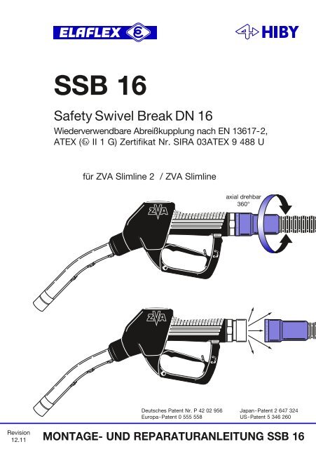
<strong>SSB</strong> <strong>16</strong>Safety Swivel Break DN <strong>16</strong>Wiederverwendbare Abreißkupplung nach EN 13617-2,ATEX (` II 1 G) Zertifikat Nr. SIRA 03ATEX 9 488 Ufür ZVA Slimline 2 / ZVA Slimlineaxial drehbar360°Deutsches Patent Nr. P 42 02 956Europa-Patent 0 555 558Japan-Patent 2 647 324US-Patent 5 346 260Revision12.11MONTAGE- UND REPARATURANLEITUNG <strong>SSB</strong> <strong>16</strong>
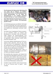
<strong>ELAFLEX</strong> SAFETY BREAKEN 13617-2WARNING REASSEMBLYAUTHORIZED PERSONNEL ONLYZapfventil Rille <strong>SSB</strong> <strong>16</strong> Wulstrand Break Sleeve BS <strong>16</strong> KS <strong>16</strong>Das SAFETY SWIVEL BREAK "<strong>SSB</strong> <strong>16</strong>" ist eine selbstschließende Abreißkupplung mitDrehgelenk, die Zapfsäule, Schlauchleitung <strong>und</strong> Fahrzeug <strong>bei</strong> Wegfahrunfällen schützen soll.Sie wird als Nozzle Break direkt am Zapfventil ZVA SLIMLINE oder ZVA SLIMLINE 2 montiert.Jedes <strong>SSB</strong> <strong>16</strong> wird vor Auslieferung auf Abriss <strong>und</strong> Druckdichtigkeit (5,25 bar gemäß NormEN 13617-2) stückgeprüft. Dies wird durch das Herstelldatum bestätigt, zum Beispiel '1420'für 1 = Montag, 42 = Kalenderwoche 42, 0 = Jahr 2010. Bei einer Zugkraft von 80 kg (800 N)bis 150 kg (1500 N) trennt sich die Kupplung, <strong>und</strong> zwar nicht nur <strong>bei</strong> axialer Überlastung,sondern auch <strong>bei</strong> Winkelbeanspruchung, wie sie in der Praxis besonders häufig vorkommt.Achtung : Vor dem Einbau muss unbedingt geprüft werden, ob die Konstruktion derZapfsäule <strong>und</strong> die Schlauchleitung eine Zugkraft von mehr als der max. möglichen Trennkraftin allen Wegfahrrichtungen zulässt.Ein Dichtkegel im Ausreißteil stoppt den Kraftstofffluss der Schlauchseite. Gemäß Sicherheitsvorschriftdürfen da<strong>bei</strong> nur max. 120 ml auslaufen. Nach einem Abriss darf das <strong>SSB</strong> <strong>16</strong>gemäß nebenstehender Vorschrift von einem autorisierten Monteur wieder zusammengesetzt<strong>und</strong> nach Prüfung der Dichtheit erneut verwendet werden. Durch die Konstruktion ist einVersprühen <strong>bei</strong>m Versuch der Wiedermontage am Schlauch nicht möglich.<strong>Montage</strong>hinweisel Zapfsäulenpumpe abstellen. Druck im Schlauch entlasten.lZapfventil von der Schlauchleitung abschrauben <strong>und</strong> Schlauch entleeren.l Vorhandenes Drehgelenk vom Zapfventil abschrauben.l Break Sleeve BS <strong>16</strong> über Schlauchverschraubung (<strong>und</strong> Knickschutz KS <strong>16</strong>) schieben.l Gewinde leicht einölen oder fetten <strong>und</strong> <strong>SSB</strong> <strong>16</strong> wieder mit aufgedrücktem Siebin das Zapfventil einschrauben.l Gewinde des <strong>SSB</strong> <strong>16</strong> ölen <strong>und</strong> die Schlauchverschraubung mit zwei SchraubenschlüsselnEW - M 36/41 festziehen – nicht in Schraubstock einspannen.l Pumpe anstellen <strong>und</strong> prüfen, ob alle Verbindungen dicht sind.l BS <strong>16</strong> über <strong>SSB</strong> <strong>16</strong> nach vorn schieben, bis der Wulstrand in die Rille einrastet.Wenn das Zapfventil bereits werksseitig mit <strong>SSB</strong> <strong>16</strong> ausgerüstet ist, erfolgt die <strong>Montage</strong> amSchlauch sinngemäß in gleicher Weise wie beschrieben.Die untere Abbildung zeigt das montierte System mit der richtigen Position des Siebes.Das Break Sleeve BS <strong>16</strong> dient <strong>bei</strong> einer Trennung dem Schutz des Ausreißteils vor Beschädigungen.Verschiedene Farben zur Produktkennzeichnung oder Darstellung der Firmenfarbesind verfügbar.Sieb
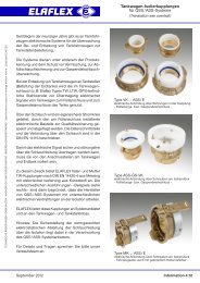
<strong>ELAFLEX</strong> SAFETY BREAKEN 13617-2WARNING REASSEMBLYAUTHORIZED PERSONNEL ONLYGehäuse <strong>SSB</strong> <strong>16</strong> Ausreißteil SchlauchverschraubungWIEDERMONTAGE UND NEUEINSATZ NACH ABRISSAchtung : Diese Ar<strong>bei</strong>t darf nur von einem autorisierten Monteur durchgeführt werden.Er überprüft da<strong>bei</strong> auch Zapfsäule, Zapfventil <strong>und</strong> Schlauchleitungsanschlüsse auf möglicheSchäden <strong>und</strong> unterzieht das ganze System vor Wiederinbetriebnahme einem Drucktest. EineWiedermontage direkt an der Schlauchleitung ist nicht möglich.a) Zapfsäulenpumpe abstellen. Druck im Schlauch entlasten.b) Break Sleeve BS <strong>16</strong> über Schlauchverschraubung (<strong>und</strong> Knickschutz KS <strong>16</strong>) zurückschieben.c) <strong>SSB</strong>-Gehäuse vom Zapfventil <strong>und</strong> <strong>SSB</strong>-Ausreißteil vom Schlauch abschrauben.Schlauch entleeren.d) Alle Teile säubern <strong>und</strong> auf mögliche <strong>bei</strong>m Unfall verursachte Schäden untersuchen wiez.B. Ovalität oder andere Deformationen oder gebrochene Kunststoffteile.Bei solchen Schäden ist ein Wiedereinsatz nicht gestattet.Außer dem sichtbaren O-Ring sind keine Einzelteile lieferbar.e) Am Ausreißteil <strong>und</strong> Gehäuse alle metallischen Gleitflächen <strong>und</strong> die Nut für den Sprengringsowie die O-Ringe dünn einfetten.f) Gehäuse in senkrechter Position halten <strong>und</strong> den Sprengring mit der Hand zentrieren.Das Ausreißteil sorgfältig von oben in das Gehäuse einführen. Die <strong>bei</strong>denKupplungshälften müssen zueinander zentrisch <strong>und</strong> unverkantet ausgerichtet sein.g) Die Teile zentrisch zusammenhalten <strong>und</strong> mit der Kraft eines Schraubstockes zusammendrücken.Sicherstellen, dass die <strong>bei</strong>den Teile da<strong>bei</strong> axial geführt bleiben, bis sie hörbar<strong>und</strong> sichtbar zusammenschnappen.h) Die notwendige <strong>Montage</strong>kraft muss in 2 Schritten aufgebracht werden. (2 aufeinanderfolgende Einrastungen). Bei spürbarem Widerstand innehalten <strong>und</strong> mit (f) noch einmalbeginnen.Danach <strong>SSB</strong> <strong>16</strong> mit BS <strong>16</strong> wieder zwischen Zapfventil <strong>und</strong> Schlauchleitung montieren <strong>und</strong>Dichtheitsprüfung unterziehen.click<strong>ELAFLEX</strong> SAFETY BREAKEN 13617-2WARNING REASSEMBLYAUTHORIZED PERSONNEL ONLYNächstgelegene ZVA-Servicefirma kann erfragt werden <strong>bei</strong> <strong>ELAFLEX</strong> HIBY TanktechnikSchnackenburgallee 121 • 22525 Hamburg • Tel. (040) 540 00 50 • Fax (040) 540 00 567
<strong>SSB</strong> <strong>16</strong>Safety Swivel Break DN <strong>16</strong>Reusable break-away coupling to EN 13617-2,ATEX (` II 1 G) certificate no. SIRA 03ATEX 9 488 Ufor ZVA Slimline 2 / ZVA Slimlineswivelling360°German Patent No. P 42 02 956Europa-Patent 0 555 558Japan-Patent 2 647 324US-Patent 5 346 260INSTALLATION AND REASSEMBLY GUIDE <strong>SSB</strong> <strong>16</strong>
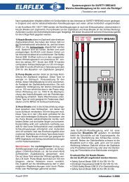
<strong>ELAFLEX</strong> SAFETY BREAKEN 13617-2WARNING REASSEMBLYAUTHORIZED PERSONNEL ONLYnozzle groove <strong>SSB</strong> <strong>16</strong> lip break sleeve BS <strong>16</strong> KS <strong>16</strong>The SAFETY SWIVEL BREAK "<strong>SSB</strong> <strong>16</strong>" is a self-sealing reusable break-away couplingdesigned to protect dispenser, hose assembly and car against damage which can occurby drive-off incidents. As a nozzle break it is directly fitted to the ZVA SLIMLINE orZVA SLIMLINE 2 nozzle. Before delivery each <strong>SSB</strong> <strong>16</strong> is tested regarding the break-off andtightness <strong>und</strong>er pressure (5.25 bar acc. to standard EN 13617-2). This is documented by thefactory date code, e.g. '1420' for 1 = Monday; 42 = calendar week 42; 0 = year 2010.When a pull between 80 kg (800 N) and 150 kg (1500N) is applied, either axially or at an angleas quite often occurs in practice, the coupling separates.warning : Before installation determine if the construction of the dispenser and the pullresistance of the hose is suitable for a pull force higher than the max. separation force,in all driveaway directions.An integral valve at the break-away part stops the flow of fuel at the hose end. Accordingto safety regulations max. 120 ml are allowed to flow out. After separation the <strong>SSB</strong> <strong>16</strong> mustbe reassembled by an authorised service engineer according to the instruction (oppositepage) and may then be used again after leakage test. The construction is such that fluid isnot sprayed out during reconnection action.installation instructionsl Switch off pump. Release pressure in hose.lRemove nozzle from hose assembly and drain hose.lRemove existing swivel from nozzle.lPush break sleeve BS <strong>16</strong> back over the hose assembly (and anti-kinking sleeve KS <strong>16</strong>).l Slightly lubricate thread; screw <strong>SSB</strong> <strong>16</strong> with assembled strainer into nozzle.l Lubricate thread and screw <strong>SSB</strong> <strong>16</strong> onto the hose assembly by using twoEW - M 36/41 wrenches, not a vice.l Prime pump and check carefully to ensure connections are tight.l Push BS <strong>16</strong> over <strong>SSB</strong> <strong>16</strong> until the lip rests in the groove.If the <strong>SSB</strong> <strong>16</strong> was factory fitted to the nozzle, the assembly on the hose is done the sameway as described above.The drawing below shows the assembled system with the correct position of the strainer.The break sleeve BS <strong>16</strong> is an integral part of the <strong>SSB</strong> <strong>16</strong> and helps protect the break-awaypart against external damage in the event of a drive-off. A range of colours is available forproduct identification to prevent misfuellings.strainerRevision12.11
<strong>ELAFLEX</strong> SAFETY BREAKEN 13617-2WARNING REASSEMBLYAUTHORIZED PERSONNEL ONLYbody <strong>SSB</strong> <strong>16</strong> break-away part hose assemblyREASSEMBLY AFTER SEPARATIONnote : This work must only be done by an authorised service engineer who should also testand check the dispenser, nozzle and hose connections for possible damage. The whole systemis then subjected to a pressure test before <strong>bei</strong>ng put into operation again.warning : This leaflet contains important information which must be read prior to assemblyequipment. The responsible person must observe their company´s procedures and safetyregulations taken into account. Fuelling equipment should regularly be visually inspected onsite to ensure it is <strong>und</strong>amaged.a) Switch off pump. Release pressure in hose.b) Push break sleeve BS <strong>16</strong> over the hose assembly (and the anti-kinking sleeve KS <strong>16</strong>).c) Unscrew <strong>SSB</strong> body from nozzle and <strong>SSB</strong> break-away part from hose.Drain hose.d) Clean all parts and check them for damages caused by the accident like ovalness orother deformations or broken plastic parts. With such damage, the safety-breakcoupling may not be reused. Except for the visible O-ring no spare parts are supplied.e) Slightly lubricate all metallic sliding surfaces of the body, the groove for the circlipas well as the O-rings.f) Hold body in vertical position and center the circlip by hand. Fit the break-away partcarefully from the top into the body. Both have to be in straight line.g) Hold parts centric and press them together with a vise. Make sure that both partsremain aligned axially until they snap together visibly and audibly.h) The necessary assembly force has to be applied in two steps (to consecutive snaps).In case of noticable resistance stop and start again at (f).Thereafter reconnect <strong>SSB</strong> <strong>16</strong> with BS <strong>16</strong> again between nozzle and hose assembly asdescribed opposite and test assembly for tightness.click<strong>ELAFLEX</strong> SAFETY BREAKEN 13617-2WARNING REASSEMBLYAUTHORIZED PERSONNEL ONLYFor address of closest ZVA service company call <strong>ELAFLEX</strong> HIBY TanktechnikSchnackenburgallee 121 • 22525 Hamburg / Germany • Tel. +49 40 540 00 5-0 • Fax -67