download PDF - bei ELAFLEX
download PDF - bei ELAFLEX
download PDF - bei ELAFLEX
- Keine Tags gefunden...

Erfolgreiche ePaper selbst erstellen
Machen Sie aus Ihren PDF Publikationen ein blätterbares Flipbook mit unserer einzigartigen Google optimierten e-Paper Software.
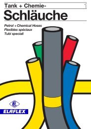
Tank + Chemie-Schläuche1Petrol + Chemical HosesFlexibles spéciauxTubi speciali
Zeichenerklärung| AB. 123 | meistgebrauchte Standardtype( AB. 123 ) auf Anfragek AB. 123 lauf AnfrageSigns and Symbols| AB. 123 | widely used standard Type( AB. 123 ) on requestk AB. 123 lin development
GRUPPE GE-WICHT1 WeightApprox.SCHLAUCH-GRÖSSEHoseSizeBetriebsdruckWork. PressurePrüfdruckTest PressureUnterdruckmax. VacuumTrommel - ØMin. Reel Dia.RollenlängeCoil LengthBESTELL-NUMMERPartNumberSection ≈ kg / m ID in. ID mm OD ≈ mm bar bar bar mm ≈ m TypeTECHNISCHE ÄNDERUNGEN VORBEHALTEN · NACHDRUCK UND KOPIEN NUR MIT UNSEREM EINVERSTÄNDNIS · Specifications subject to change without notice · Copyright <strong>ELAFLEX</strong>0,3 3⁄8" 10 190,8 100HD 10 Hochdruck-Tankschlauch 'Gelbring' ohne Wendel nach TRbF 131.0,4 1⁄2" 13 22 0,8 140 40 HD 13Ideal als Trommelschlauch für Mineralölprodukte aller Art.Temperaturbereich - 30° C bis + 90° Celsius (kurzzeitig bis + 110° C).Elektrischer Widerstand < 10 6 Ohm. Bauartzugelassen nach0,6 3⁄4" Bundeswehrnorm VG 95955 Typ D. Eichfähig nach Vorschrift19 31 0,6 200 HD 19der PTB. Entspricht EN 12115.0,8 1" 25 37 0,5 200HD 25Innen : Nitril (NBR) schwarz, auslaugfest1,0 1¼ " 32 44 0,4 22530HD 321,1 1⅜ " 35 47 0,4 250 +40 ( HD 35 )+1,2 1½ " 38 51 25 40 0,3 270 50 HD 38+1,4 – 40 54 0,3 270 60 HD 40+1,6 1¾ " 45 59 0,3 30080HD 451,9 2" 50 66 0,3 400 HD 502,4 2½ " 63 79 0,2 6003040HD 632,8 3" 75 91 – 600HD 75403,7 4" 100 116 20 – 900 HD 100Der Innengummi ist quellfest, auslaugungsbeständig, kältefl exibel, nicht ausfärbendund nicht verhärtend. Der Außengummi ist hervorragend abriebfest und absolutwitterungsbeständig. Entspricht Werkstoff NBR 1 der EN 12115, Farbkennzeichnung : gelb.Kennzeichnung: Gelbe Markenringe alle 4 mtr. u. einvulkanisierte Prägebandstempelung.HD 40 · MINERALOELPRODUKTE · 90°C · PETROLEUM PRODUCTS · R < 106 Ω · TRBF 131 · Ω ·PN 25 · <strong>ELAFLEX</strong> GERMANY · TRS · · 3Q-13The lining is resistant to swelling, solubility and discolouration. It is flexible at lowtemperatures. The cover is resistant to abrasion and weathering and furthermore providesa very good low temperature flexibility. Meets the material group NBR 1 of the EN 12115.Marking : Yellow bands every 4 mtr. Continuous, vulcanised embossing as per example above.2,3 – 60 76f. Rohr / tube~ 60 mm ODHD-RV 602,9 3" 75 91 ~ 76 mm OD 40 HD-RV 7516 253,3 – 90 106 ~ 89 mm OD HD-RV 903,9 – 110 126 ~ 108 mm OD 30 HD-RV 110Zur Beachtung : In Saugleitungen dürfen die Rohrabstände nicht größer sein alsder Innendurchmesser. Schlauchschellen Type SK siehe Seite 291.––––Please note : When used for suction the distance between the pipe ends must not be largerthan the inner diameter. Hose clamps type SK see catalogue page 291.Festigkeitsträger : Zwei dehnungsarme Textilgeflechte für extremniedrige Volumenzunahme unter DruckAußen : Chloroprene (CR), schwarz, leitfähigHD 50 · VG 95955 · TRRohrverbindungsschlauch 'Gelbring' ohne Wendel hochflexibel.Ausführung, Werkstoffe und Verwendungsbereich wie Type HD.SK SKHD 0TRbF 131 · Ω · <strong>ELAFLEX</strong> TPE'Yellow Band' hose for flexible pipe joints, without helix, highly flexible.Design, material and application same as type HD high pressure hose.0,8 1" 25 370,5 200( XHD 25 ) Heizöl-Trommelschlauch 'Economy' ohne Wendel für Mineralölprodukte.1,0 1¼ " 32 44 0,4 200 XHD 32Temperaturbereich bis + 65° C. Elektrischer Widerstand< 106 Ohm.1,2 1½ " 38 51 0,3 270 XHD 38Innen : NBR schwarz, elektrisch ableitfähigFestigkeitsträger : Zwei dehnungsarme Textilgefl echte1,4 – 40 54 20 30 0,3 270 40 XHD 40Außen : NBR / PVC, schwarz1,6 1¾ " 45 59 0,3 300 XHD 452,0 2" 50 64 0,3 400 XHD 502,8 3" 75 91 – 600 ( XHD 75 )Vereinfachte Ausführung der Type HD. Die hohen Qualitätsanforderungen der VG-Norm fürKälteflexibilität, Auslaugungsbeständigkeit, Nichtverfärbung des Mediums, Abriebfestigkeitund Witterungsbeständigkeit werden von dieser preisgünstigen Ausführung nicht erreicht.Kennzeichnung : Fortlaufende einvulkanisierte Prägebandstempelung ohne Farbringe.XHD 50 · EN 1761 · D · HEIZÖL-DIESEL-FUEL OIL · ECONOMY · R < 106 Ω · TRbF 131 · Ω ·PN 20 BAR · <strong>ELAFLEX</strong> GERMANY - - 3Q-13Simplifi ed version of hose type HD. The high quality standards of the German MilitaryStandard are not met in all respects by this Economy type, e.g. cold fl exibility, nondiscolourationof the medium as well as the resistance to abrasion and weathering.Marking: Continuous, vulcanised embossing (example above) without coloured bands.Type HD'Yellow Band' high pressure fuelling hose without helix for reeloperation. Ideal for all petroleum based products. Temperaturerange - 30° up to + 90° C (temporarily up to 110° C). Electricalconductivity < 10 6 Ohm. Can be according to PTB regulations.Approved acc. to German military standard VG 95955 Typ D.Corresponds to EN 12115.Lining : Nitrile rubber (NBR) black, no fuel-solubilityReinforcements : Two low tensile textile braids for extreme lowvolume increase under pressure.Cover : Chloroprene (CR), black, conductiveFHD-Schläuche – fl ach aufrollbar, siehe Seite 129FHD-hoses – collapsible marine hose, see page 129Type HD-RVType XHDType FHD<strong>ELAFLEX</strong> TYPE XHDEconomy fuel oil reel hose without helix for petroleum basedproducts. Temperature range up to + 65° C. Electrical conductivity< 106 Ohm.Lining : Nitrile rubber (NBR), black, electrically dissipativeReinforcements : Two low tensile textile braidsCover : Nitrile rubber / PVC, black1990Revision 9.2013Gelbring :Der Maßstab unter den Tankschläuchen––––Yellow Band :setting the standard for refuelling hosesDrucktankschläuche ohne WendelFUELLING HOSES WITHOUT HELIX103
Druckverlust in <strong>ELAFLEX</strong> - 'HD' Schläuchen · Pressure Drop for <strong>ELAFLEX</strong> 'HD' HosesErgebnisse von Prüfstandmessungen für <strong>ELAFLEX</strong>-Schläuche 10 m lang,mit glatter Innenwand, mit Diesel. Viskosität ~ 2 mm² / s (1,1 Englergrad)Results of testing for <strong>ELAFLEX</strong> hoses, smooth-bore, 10 mtr. long withdiesel / viscosity ~ 2 mm 2 / s (cST) - 1,1 degree 'Engler'Schlauchgröße / Hose size [ID mm]Druckverlust für 10 mtr · Pressure drop for 10 metresbar200Beispiel : Gesucht wird der Druckverlust eines 50 m langen Schlauchesmit 38 mm inneren Durchmesser ( ID ) <strong>bei</strong> einer angenommenen Durchflussleistungvon 300 Liter je Minute.Lösung : Der für 10 m abgelesene Druckverlust von 0,53 bar ( gestrichelteLinie ) muss mit 5 multipliziert werden. Es ergeben sich somit ca. 2,65 bar.Zur Beachtung : Bei aufgetrommelten Schläuchen erhöhen sich dieangegebenen Druckverlustwerte je nach Schlauchdurchmesser, Trommeldurchmesserund Strömungsgeschwindigkeit um ca. 25 bis 40 %.Innen gerippte Schläuche haben wesentlich höhere Druckverluste.Example : We look for the pressure drop for a hose with a length of 50 metresand ID 38 mm with an expected flowrate of 300 litres per minute.Solution : The pressure drop of 0,53 bar statet for 10 m ( dotted line ) is tobe multiplied with 5. You will fi nd a result of approx. 2,65 bar for a lengthof 50 m.Please note : The stated pressure drop values increase for reeled hosesdepending on the hose and reel diameter and the fl ow speed by approx.25 to 40 %. Hoses with rough bore tubes are subjekt to increasingly higherpressure drops.104
TECHNISCHE ÄNDERUNGEN VORBEHALTEN · NACHDRUCK UND KOPIEN NUR MIT UNSEREM EINVERSTÄNDNIS · Specifications subject to change without notice · Copyright <strong>ELAFLEX</strong>GRUPPE GE-WICHT1 WeightApprox.SCHLAUCH-GRÖSSEHoseSizeBetriebsdruckWork. PressurePrüfdruckTest PressureUnterdruckmax. VacuumBiegeradiusBend. RadiusRollenlängeCoil LengthBESTELL-NUMMERPartNumberSection ≈ kg/m ID in. ID mm OD ≈ mm bar bar bar mm ≈ m Type0,8 3⁄4" 19 3170TW 190,9 1" 25 37 80 TW 251,2 1¼ " 32 44 90 TW 321,4 1½ " 38 51 100 TW 3820 302,1 2" 50 66 130 40 TW 502,8 2½ " 63 79 160 TW 630,83,3 3" 75 91 180 TW 753,5 – 80 96 190 ( TW 80 )4,7 4" 100 116250 TW 1007,6 5" 125 145 350STW 12516 25409,7 6" 150 172 500 STW 15014,9 8" 200 224 100020(30) STW 200Der Innengummi der Typen TW, LTW und STW ist quellfest, diffusionsarm, kälteflexibel,nicht ausfärbend und nicht verhärtend, dafür aber ozonempfi ndlich. Unbenutzte Schläuchedaher nur mit verschlossenen Enden lagern. Der Außengummi ist sehr abriebfestund absolut witterungsbeständig. Entspricht Werkstoffgruppe NBR 1 der EN 12115.Kennzeichnung: Gelbe Markenringe alle 2,5 mtr. u. fortlaufende Prägebandstempelung:TW 50 · EN ISO 1825 E · EN 1361 E · EN 12115 · NBR 1 · SD · Ω/T · EN 1761 · VG 95 955 S ·KRAFTSTOFFE · PETROLEUM PRODUCTS · TRbF 131 · Ω · PN 20 BAR · <strong>ELAFLEX</strong> 2Q-13The tube of the types TW, LTW and STW is resistant to swelling and diffusion, does notstiffen and is fl exible at low temperatures. However, the hose tube is sensitive to ozone.Therefore unused hoses must be stored with capped ends. The cover is very resistantto abrasion and weather. Meets the material group NBR 1 of EN 12115.Marking: Yellow bands every 2,5 mtr. Continuous embossing as per example above.1,9 2" 50 642,8 3" 75 89 10 16 0,5 100 40 LTW 7590LTW 504,2 4" 100 115 150 LTW 100Andere Abmessungen (z. B. 63, 125, 150) auf Anfrage. Die Type LTW erfüllt die TRbF 131/2mit Nenndruck PN 10 und Berstdruck > 40 bar. Für Druckbetrieb wird jedoch wegen derLängung der hochfl exiblen Konstruktion die Verwendung nur für die üblichen Abfülldrückebis max. 6 bar empfohlen.Kennzeichnung: Gelbe Markenringe alle 2,5 mtr. und fortlaufende Prägebandkennzeichnung:LTW 50 · NBR · SD · R < 106 Ω · TRbF 131 · Ω · PN 10 BAR · <strong>ELAFLEX</strong> GERMANY · · 2Q-13Other dimensions (i.e. 63, 125, 150) on request. Type LTW meets the German safetyregulations TRbF 131/2 with a nominal pressure of 10 bar and a minimum burst pressureof 40 bar. Due to the elongation of the fl exible construction only apply the usual fillingpressure up to maximum 6 of bar for pressure operation.Marking: Yellow bands every 2,5 mtr continous embossing as per example above.0,9 1" 25 372,1 2" 50 64 16 25 0,8 200 40 XTW 5080XTW 251,2 1¼ " 32 44 90 XTW 321,4 1½ " 38 51 100 XTW 382,6 2½ " 63 78 220 XTW 633,3 3" 75 90 250 XTW 754,8 4" 100 116 0,7 350 XTW 100Vereinfachte Ausführung der Type TW. Die hohen Qualitätsanforderungen der VG-Norm fürKältefl exibilität, Auslaugungsbeständigkeit, Nichtverfärbung des Mediums, Abriebfestigkeitund Witterungsbeständigkeit werden von dieser preisgünstigen Ausführung nicht erreicht.Kennzeichnung: Fortlaufende einvulkanisierte Prägebandstempelung ohne Farbringe.XTW 50 · EN 1761 · SD · HEIZÖL - DIESEL - FUEL OIL - ECONOMY · TRbF 131 · Ω · PN 16 BAR · <strong>ELAFLEX</strong> 2Q-13Simplifi ed version of hose type XTW. The high quality standards of the German MilitaryStandard are not met in all respects by this Economy type, e.g. cold fl exibility, nondiscolourationof the medium as well as the resistance to abrasion and weathering.Marking: Continuous, vulcanised embossing (example above) without coloured bands.Tankwagenschlauch 'Gelbring' mit abknickfester Stahlwendel,nach TRbF 131/2, innen und außen glatt. Für Mineraloelproduktealler Art. Temperaturbereich - 30° bis + 90° C (kurzzeitig bis 110° C).Elektrischer Widerstand < 106 Ohm. Bauartzugelassen nachNorm VG 95 955 Typ S. Entspricht EN 12115 und EN 1761.Type STW = verstärkte TW-Ausführung. Besonders geeignet alsMarine-Bunkerschlauch (Einzelheiten siehe Seite 129).Innen : NBR, leitfähig, auslaugungsfestFestigkeitsträger : Textilgeflechte und dazwischenliegendeverzinkte Stahlwendel in der LeitschichtAußen : Chloroprene ( CR ) schwarz, leitfähigType TW'Yellow Band' smooth bore tank truck hose with kink resistantsteel helix for all petroleum based products. Temperature range- 30° up to + 90° Celsius (temporarily up to 110° C). Electricalconductivity < 106 Ohm. Approved to German military standardVG 95 955 type S. Complies with EN 12115 and EN 1761.Type STW = reinforced TW design. Particularly suitable as marinebunker hose (details see catalogue page 129).Lining : NBR, conductive, black, no fuel solubilityReinforcements : Textile braids and embedded non-kinkinggalvanised steel helix in the conductive layerCover : Chloroprene ( CR ) black, conductiveLeicht-Tankwagenschlauch 'Gelbring', innen glatt, außengewellt: Leicht zu handhaben durch sehr gute Flexibilität, engeBiegeradien und geringes Gewicht. Einsatzbereich, Werkstoffeund gelbe Ringe wie Type TW.Type LTWLT0L W 50-LTW 50 - NBR - SD - R
Umgang mit <strong>ELAFLEX</strong>-Schläuchen (Stand 5.2013) How to look after <strong>ELAFLEX</strong> hoses (update 5.2013)LAGERUNG:Schläuche spannungsfrei, ohne Knickung, in trockenen, dunklen, kühlen, staubfreien undmäßig gelüfteten Räumen lagern.Temperaturbereich für Lagerung + 30 bis - 30° C. Schläuche nicht direkt an Heizkörpernund Heizungsrohren lagern. Die Inbetriebnahme elektrischer Geräte, Motoren und Anlagenmit Funkenbildung sowie Erzeugung von Hochspannungsfeldern in diesen Räumen vermeiden,da diese schädliches Ozon erzeugen.Zum Schutz des Innengummis gegen Ozoneinwirkung und Verschmutzung Schläuchemit Schutzkappen versehen. Dies gilt besonders für Schläuche mit spezialisiertemInnengummi, wie z. B. Flugzeugbetankungs- und Lösungsmittelschläuche. BeiSchläuchen, die im Freien lagern, ist ein Verschließen der Enden unbedingt notwendig.Schläuche dürfen nicht so hoch gestapelt werden, dass unten liegende Schläuchebleibende Verformungen erhalten. Bei längerer Stapellagerung stark belastete Schläuchein druckfreie Zonen umschichten. Schlauchleitungen so lagern, dass die Armaturen nichtden weichen Schlauchverband eindrücken oder verletzen können.REINIGUNG AUSSEN:Für eine Reinigung dürfen keine aggressiven Reinigungsmittel wie Benzol, Benzin, Terpentino.ä. verwendet werden. Warmes Wasser, Seife oder P3-Lauge ist normalerweise ausreichend.Ein Abreiben mit Glyzerin erzeugt neuwertiges Aussehen. Farbanstriche auf Schläuchensind zu unterlassen.Erkaltete Bitumen- oder Teerreste nicht mit der Lötlampe entfernen! Die Betriebssicherheitwürde dadurch herabgesetzt. Bitte Sonderhinweise für die Reinigung von 'HB'-Schläuchenauf Seite 136 beachten.REINIGUNG INNEN:Vor dem Durchleiten besonders empfi ndlicher Medien (Verfärbung) wird <strong>bei</strong> Inbetriebnahmeneuer Schläuche empfohlen, den Innengummi zu reinigen. Ausschwitzende Gummibestandteile,Transport- / Montageverunreinigungen und Kondenswasserbildung könnenzu Verfärbungen führen. Gebräuchlich sind nach Art der Medien und der Schläuche z.B.Durchspülen mit warmem Wasser, P3-Lauge, kurzzeitiges Ausdämpfen oder eine ein- bzw.mehrmalige Füllung mit dem zur Verwendung kommenden Medium für ein bis zwei Tage.ÜBERWACHUNG UND DRUCKPRÜFUNG:Schlauchleitungen sind regelmäßig visuell auf Schäden und Undichtigkeit zu prüfen undwiederkehrend einer Druckprüfung zu unterziehen. <strong>ELAFLEX</strong> empfi ehlt, dass eine visuelleKontrolle zu Beginn und zum Ende der Nutzung einer Schlauchleitung durchgeführt wird - <strong>bei</strong>kontinuierlicher Nutzung z. B. <strong>bei</strong> Schichtwechsel. Die jeweilig anzuwendenden Standardsund Vorschriften für die Überwachung und Prüfung von Schlauchleitungen sind zu berücksichtigen(Beispiele: 'JIG' für die Flugzeugbetankung oder die 'T002' für Chemieschläuche).Allgemein gilt in Europa: Nach Richtlinie 2009/104/EG und daraus folgend in Deutschlandnach BetrSichV, dass der Betreiber vor dem Einsatz einer Schlauchleitung eine Risikobeurteilungdurchführen muss, da nur er den genauen Einsatzfall und die sich daraus ergebendenMaterialbelastungen und Risiken kennt.LEITFÄHIGKEITSPRÜFUNG:Entsprechend der gültigen Normen und Vorschriften darf der elektrische Widerstandeiner Schlauchleitung – zwischen den Anschlussarmaturen gemessen – z.B. für einenΩ- oder Ω/T- Schlauch 1 Million Ohm (10 6 Ohm) nicht überschreiten. Da der elektrischeWiderstand durch Einfl üsse während der Betriebszeit, z.B. Biegung, Alterungsrisse, Quellung,Diffusion und Abrieb normalerweise erheblich ansteigt, sind von den Herstellern neueSchläuche mit einem niedrigeren Widerstand, z.B. ca. 100.000 Ohm, zu liefern. Der Betreiberhat sich durch Wiederholungsprüfungen während des Betriebes davon zu überzeugen, dassauch <strong>bei</strong> älteren Schläuchen der maximal zulässige Widerstandswert nicht überschrittenwird. Schläuche mit einem höheren elektrischen Widerstand sind eine Gefahrenquelle undaußer Betrieb zu nehmen.BETRIEB:Starke Unterschreitung des zulässigen minimalen Biegeradius führt oft zu vorzeitigemAusfall von Schläuchen. Insbesondere <strong>bei</strong> Schläuchen mit Wendel und Schläuchenmit thermoplastischer Innenschicht darf der Biegeradius nicht mit Gewalt überzogenwerden, um Einknickungen bzw. Beschädigungen der Innenschicht zu vermeiden.Dies gilt speziell für den Bereich in der Nähe der Schlaucheinbindungen. KeinSchlauch darf direkt hinter der Armatur über Eck geknickt oder gezogen werden.Bunkerschläuche nicht nur an einem Punkt aufhängen; das Armaturengewicht ist abzufangen.Ein Verdrehen des Schlauches um seine Längsachse ist grundsätzlich zu vermeiden.Wenn eine Schlauchleitung über einen befahrenen Weg verlegt werden muss, sindSchlauchbrücken zum Schutz des Schlauches zu verwenden.Außengummi und Schnittfl ächen des Schlauches dürfen nicht mit dem Durchfl ussmediumin Berührung kommen oder in Öllachen liegen.Ein ständiges Scheuern des Schlauchmantels gegenüber seiner Umgebung bzw. Halterungmuss verhindert werden.Bei Leerschlauchbetrieb sind aggressive Flüssigkeitsreste nach Gebrauch durch geeigneteMaßnahmen zu entfernen. Hierdurch wird eine längere Nutzungsdauer der Schläucheerreicht. Nach Entleerung sind die Schläuche grundsätzlich zu verschließen. Ausnahme:Dampf- und Heißbitumenschläuche nach der Entleerung bis zum Erkalten offen lassen,damit sich im Schlauch kein Vakuum bildet, das zur Zerstörung des Schlauches führenwürde (siehe auch Hinweis auf Seite 136).STORAGE :To ensure maximum service life, hoses should be stored free of kinks, twist or compression,in dry, dark, cool, dust-free, regularly vented rooms.Permissable ambient temperature range + 30° C up to - 30° C. Hoses should not be storednear to heating elements and heating pipes. Electrical equipment which can producesparks or a strong electric fi eld will produce harmful ozone and should therefore not beused in the storage rooms.Open ends must be plugged (capped) to protect the lining from ozone and otherpollution. This is especially important for hoses with a highly specialised rubberlining, e. g. aviation and solvent hoses. Hoses stored outdoors must be protectedwith caps at any time.Do not stack coils too high to avoid deforming the coil at the bottom. When stored for along period, hoses should be shifted into pressure-free zones from time to time.For complete hose assemblies, please take care to avoid fi ttings pressing against thehose wall.CLEANING OF THE COVER :For cleaning, do not use aggressive media like benzene, gasoline, turpentine or alike.Usually, warm water, soap or soapsuds are recommended for cleaning. After cleaning,glycerine may be used to give the hose a reconditioned look. Never paint a hose.Bitumen hoses : asphalt and tar residues on the cover should not be removed with a torchlamp! The operating safety would decreased. Please note special hints for cleaning 'HB'hoses see page 136.CLEANING OF THE TUBE:It is recommended to clean the lining of new hoses before putting it into service,especially when sensitive media will be transferred (discolouration). Discolouration canoccur through rubber particles, dirt from transport / assembly or condensing water.Depending on the medium hoses can be fl ushed with warm water, soapsuds or fi lled withthe medium to be used for one or two days. Many hose types can be temporarily steamedout (open system).INSPECTION AND PRESSURE TESTS:Hose assemblies must be visually checked for damages / leakages and pressure testedon a regular basis. <strong>ELAFLEX</strong> recommends a visual inspection when starting and endingusing a hose. When continuously using a hose the visual inspection could be made at thebeginning and end of work shifts.The respective applicable standards and regulations for the inspection and testing of hoseassemblies have to be considered (example: 'JIG' rules for into plane aviation hoses).Europe: according to Directive 2009/104/EC, before using a hose the operator has to performa risk analysis, because only he knows the exact application and the resulting materialloads and risks.CONDUCTIVITY TEST :According to current technical specifications the electrical conductivity of a hose (forexample Ω- or Ω/T- hose) a must not exceed 1 million Ohm (10 6 Ohm ) during servicebetween end fi ttings. Suppliers are imposed delivering new hoses with lower conductivity,i.e. 100.000 Ohm, because the electrical conductivity increases during the hose lifetime dueto bending, age-caused cracks in the cover, swelling, diffusion and abrasion.The operator should periodically check that for older hose assemblies the value of max.allowable electrical resistance is not exceeded. Hoses with a higher electrical resistancefor the use with dangerous media must be put out of service.OPERATION :Always observe the permitted bending radius. A main reason for the prematurefailure of hoses is the disregard of the minimum bending radius (see cataloguedata). Hoses with helix and hoses with thermoplastic linings are more sensitiveto kinking. Avoid overbending especially near the end fittings. In order to avoiddamages, no hose should be kinked or pulled around corners directly behind thefittings.Do not suspend bunkering hoses only at one point, and compensate the weight of thefi t t i n g s .Avoid torsion (twisting) of hoses.If a hose has to be laid across a traffic lane, it must be protected agains <strong>bei</strong>ng run overwith hose bridges.The outer cover and cut edges of a hose should not come in contact with the medium orlie in oil spills.Permanent scuffi ng (abrasion) of the hose cover should be avoided.After dry hose operation (when a hose is emptied) remaining aggressive fl uids shouldbe removed. Afterwards hose ends should be closed. This extends the service-life ofthe hose. Exception: steam and bitumen hoses must be left open after emtying untilcooled down, so that no vacuum can create which could destroy the hose (please notehints on page 136).REPARATUREN:Schadenstellen an gebrauchten Schlauchleitungen lassen sich grundsätzlich nicht durchFlicken, Umwickeln oder Nachvulkanisieren reparieren. Auch wird davon abgeraten,abgeknickte Wendelschläuche auszubeulen, besonders dann, wenn die Spiralknickstelleaußen sichtbar ist. Beschädigte Abschnitte müssen herausgeschnitten und z.B. durchTrommelschlauchverbinder neu zusammengesetzt werden.Bei Kürzung defekter Schläuche ist zu beachten: Der Schlauch muss soweit abgeschnittenwerden, wie eine Schichtentrennung zu erkennen oder Flüssigkeit in das drucktragendeGewebe eingezogen ist. Daher den Schlauch nicht mit der Eisensäge, sondernmit scharfem Messer in 10 cm Schritten kürzen. Schlauchwand zwischen Daumen undZeigefi nger zusammenpressen, das Gewebe muss trocken bleiben. Nur <strong>bei</strong> einem glattenSchnitt kann man Feuchtigkeitsaustritte sicher erkennen.Wenn die Armatur sich nur schwer montieren lässt: Keinenfalls den Innengummi anschneiden(anfasen) oder mit dem Schlauchstutzen verletzen. Nur der Außengummi darfangeschliffen oder abgepellt werden. Das drucktragende Gefl echt da<strong>bei</strong> nicht verletzen.Nur ein erheblicher Montagekraftaufwand gewährleistet einen sicheren Armaturensitz.Wenn der Innengummi zu stark angequollen ist, Schlauchende 24 Stunden austrocknenlassen und erneut versuchen. Zur Montage dürfen keine Klebe-, Dicht- oder Schmiermittelverwendet werden, die den Leitfähigkeitsübergang zwischen leitfähigem Gummi undMetallarmatur beeinträchtigen könnten. Als Gleitmittel empfi ehlt sich Wasser oder Seife.106REPAIRS :Hoses cannot be effectively and safely repaired by patching, wrapping or re-vulcanizing.When permanently kinked, hoses with helix should not be rebent or dinged back,especially when the bent helix is clearly visible. Damaged sections should be cut off.It is possible to re-assemble with double shank hose connectors.When damaged hoses are shortened, please observe that the hose must be cut backsufficiently to ensure that the hose layers are not separated and that the fuel hasnot penetrated into the textile reinforcements. Cut the hose with a sharp knife in 10 cmsteps - do not use a saw. Press the wall of the hose between thumb and index fi nger.The reinforcement must be dry. Only with a smooth cut, damp parts can be recognizedeasily.If difficulties are experienced with putting on the end fi ttings, never trim or abrade thelining. If necessary, the outer cover may be trimmed or abraded, but take care not to damagethe textile reinforcements.Physical effort on assembling the fi tting provides that it fi ts safely, but avoid damagingthe lining when the hose tail is inserted. If the lining has swollen, allow it to dry out for24 hours and try again. Proceeding these guidelines ensures a longer service-life of the hose.Do not use adhesives, sealants or lubricants for the assembly, because these couldinterfere the electrical continuity. Water or soap can be used as lubricant.– siehe auch 'Betriebsanleitung <strong>ELAFLEX</strong>-Schlauchleitungen und Kompensatoren' – – see also 'Operation Instructions <strong>ELAFLEX</strong> hose assemblies and expansion joints' –
'ltX' -leicht-tankwagenschlauchfür die schwerkraftabgabe( Translation see overleaf )TECHNISCHE ÄNDERUNGEN VORBEHALTEN · NACHDRUCK UND KOPIEN NUR MIT UNSEREM EINVERSTÄNDNIS · Specifications subject to change without notice · Copyright <strong>ELAFLEX</strong>Der Trend geht zu immer weniger, da<strong>bei</strong> immer größerwerdenden Tankstellen. Dies führt zu erhöhten An -sprüch en an die Tankwagenschläuche: zur Befüllungder Erdtanks werden höchste Flexibilität (auch imWin ter betrieb), bestes Handling, niedriges Gewicht,hohe Durch fluss leistung und Langlebigkeit im hartenDauer einsatz gefordert.Als preiswerte und extrem leicht zu handhabendeQualitätsalternative präsentiert <strong>ELAFLEX</strong> die TypeLTX, die ausschließlich für den drucklosen Betrieb(Schwerkraftabgabe) entwickelt wurde.Ge- SCHLAUCH- BESTELLwichtGRÖSSE NUMMERNenndruck~~ kg/m ID in. IDmm OD mm bar bar bar mm ~ m Type2,1 3" 80 93 100 LTX 804 6 0,5 40*)3,2 4" 100 115 150 LTX 100Schlaucharmatur für LTX 80 mit 3" Außengewinde / Spannfix-Einbindung VLTX 80-3"Schlaucharmatur für LTX 100 mit 4" Außengewinde / Spannfix-Einbindung VX 100-4"PrüfdruckEinsatzgEbiEt / tEchnischE DatEnLeichter, hochflexibler Abgabeschlauch für die Tank stel -len versorgung im Schwer kraftbetrieb. LTX ist sehr gutgeeignet für den Einsatz mit ASS/QSS-Sys te men,und als Gaspendel schlauch.Druckstufe PN 4, Berstdruck > 16 bar. Für die Nutzungin Deutschland ist zu berücksichtigen, dass LTX nichtder TRbF 131 Teil 2 entspricht. Eine vorliegendeGutachterliche Stellungnahme des TÜV NORD (alsDownload unter www.elaflex.de) ermöglicht denEinsatz des Schlauches in Deutschland unter Einhaltungder dort genannten Bedingungen.Geeignet für Mineralöl pro duk te aller Art mit bis zu50% Aromaten anteil. Temperaturbereich -30°C bis+90° C. Elektrischer Widerstand < 10 6 Ohm.Innen : NBR, antistatisch, auslaugungsfestFestigkeitsträger : Textilgeflecht mit eingebetteter,abknickfester, verzinkter StahlwendelAußen : CR, schwarz, elektrisch ableitfähig,mit Spezial ein schnü run genVortEilEl Geringeres Gewicht, höhere Flexibilität und nied -ri gere Rückstellkräfte als alle marktbekanntenSchlauch konstruktionenl Bleibt auch im Winter sehr flexibell LTX 80: echte 80 mm innerer Durchmesser, außenca. 93 mm - passt in jedes Schlauchrohrl Keine störende äußere Spirale, die sich amSchlauchrohr des Tankwagens verhaken kannUnterdruckBiegeradiusRollenlängeKennzeichnung : Gelbe Spiralmarkierung und PrägebandstempelungLTX 80 . NBR . SCHWERKRAFT / GRAVITY . W . PN 4 BAR . <strong>ELAFLEX</strong> 02.11März 2008 (Revision Februar 2011) information 1.08
'ltX' -lightweight gravity dischargeRoad tanker HoseThe number of forecourts are diminishing whilst sitesand volume throughput is increasing. This is puttinggrowing demands on the road tanker hose.For the loading of UST’s (underground storage tanks)operators and drivers expect optimum handling, lightweight,excellent flexibility, high flowrates and longservice life under tough operating conditions.<strong>ELAFLEX</strong> presents its new type LTX hose, developedfor gravity discharge. It offers unrivalled handlingproperties and is competitively priced.Marking : Yellow Spiral and continuous embossingLTX 80 . NBR . SCHWERKRAFT / GRAVITY . W . PN 4 BAR . <strong>ELAFLEX</strong> 02.11Weight Hose PartApprox. Size NumberNom.Pressure~~ kg/m ID in. IDmm OD mm bar bar bar mm ~ m Type2,1 3" 80 93 100 LTX 804 6 0,5 40*)3,2 4" 100 115 150 LTX 100Test PressureHose fitting for LTX 80 with 3" BSP male thread / Spannfix clamps VLTX 80-3"Hose fitting for LTX 100 with 4" BSP male thread / Spannfix clamps VX 100-4"max. VacuumBend. RadiusCoil LengthApplicAtion / tecHnicAl dAtALightweight and highy flexible gravity discharge hosefor loading from road tankers to UST. LTX can alsobe used with electronic control safety devices. Alsosuitable as vapour recovery hose (Stage 1b).Nominal pressure PN 4, burst pressure > 16 bar.Only use for gravity discharge.For all petroleum based products including hydrocarbonvapours, aromatics content up to 50%. Temperaturerange -30°C up to +90° C. Electr. resistance < 10 6 Ohm.Lining : NBR, antistatic, no fuel solubilityReinforcements : Textile braids with incorporated,kink resistant galvanized steel helixCover : CR, black, electrically conductive,with special corrugationsAdvAntAgesl Lower weight, higher flexibility and lower bendingforce compared to all known road tanker hoseconstructionsl Stays flexible also in cold temperature conditionsl LTX 80: true bore 80 mm ID, approx. OD 93 mm- will fit road tanker stowage tubesl Hoses and fittings fit snugly into the stowage tubewithout getting hookedinformation 1.08March 2008 (Revision Feb 2011)
GRUPPE GE-WICHT1 WeightApprox.SCHLAUCH-GRÖSSEHoseSizeBetriebsdruckWork. PressurePrüfdruckTest PressureUnterdruckmax. VacuumTrommel - ØMin. Reel Dia.RollenlängeCoil LengthBESTELL-NUMMER ¹)PartNumber ¹)Section ≈ kg / m ID in. ID mm OD ≈ mm bar bar bar mm ≈ m TypeTECHNISCHE ÄNDERUNGEN VORBEHALTEN · NACHDRUCK UND KOPIEN NUR MIT UNSEREM EINVERSTÄNDNIS · Specifications subject to change without notice · Copyright <strong>ELAFLEX</strong>Spezifikation: Erfüllt Standard nach EN ISO 1825 (EN 1361), EI (API) 1529 C, NFPA 407,AS 2683, sowie TRbF 131. Bauartzulassung nach VG 95 955. Von nahezu allen großenÖlgesellschaften spezifiziert. Weitere technische Daten und Sonderausführungen umseitig.Kennzeichnung: Gelbe Markenringe alle 4 mtr. und fortlaufende Prägebandstempelung:HD 100 C · EN ISO 1825 C · EN 1361 C · EN 12115 NBR 1 · D · Ω/T · EN 1761 · VG 95 955 D· API 1529 C · AS 2683 · TRbF 131 · Ω · PN 20 BAR · <strong>ELAFLEX</strong> GERMANY · · 3Q-13Specification: Meets Standard EN ISO 1825 (EN 1361), EI (API) 1529 C, NFPA 407,AS 2683 and German safety regulation TRbF 131. Approved acc. to German militarystandard VG 95 955. Specifi ed by almost all major oil companies. Further technical dataand types see overleaf.Marking: Yellow bands every 4 mtr. and continuous embossing as example above.0,6 3⁄4" 19 310,6 200 40HD 19 C(HD 19 C NEON)0,8 1" 25 37 0,5 2001,0 1¼ " 32 44 0,4 2251,2 1½ " 38 51 0,3 2701,9 2" 50 6620 400,2 4002,4 2½ " 63 79 0,15 6002,8 3" 75 91 – 6003,7 4" 100 116 – 90030 +40+50 +60+8030 +4040HD 25 C(HD 25 C NEON)HD 32 C(HD 32 C NEON)HD 38 C(HD 38 C NEON)HD 50 CHD 50 C NEON(HD 63 C)HD 63 C NEONHD 75 C(HD 75 C NEON)HD 100 CHD 100 C NEON ²)Einsatzbereich: Hydranten-, Trommelschlauch. Bis DN 63 auch als Deckschlauch. DerSchlauch knickt nicht ein, wenn der Innendruck ständig mindestens 0,5 bar beträgt.––––Application: Hydrant inlet and into-plane hose. Up to size 2½" as deck hose. The hosedoes not kink with a permanent pressure of least 0,5 bar.1,4 1½ " 38 520,6 400 402,0 2" 50 67 0,5 500 30+2,8 2½ " 63 81 20 40 0,4 550 403,4 3" 75 93 0,2 6004,4 4" 100 118 – –40(VHD 38 C)VHD 38 C NEON(VHD 50 C)VHD 50 C NEON(VHD 63 C)VHD 63 C NEON(VHD 75 C)VHD 75 C NEONVHD 100 CVHD 100 C NEON ²)Einsatzbereich : Hydranten-, Trommel- und Deckschlauch, als Verbindung zur Hebebühne.Im drucklosen Zustand neigt diese Type nicht so leicht zum Einknicken oder Abflachen.––––Application : Fortified hose suitable for reel-, into-plane and hydrant inlet operations, as well asriser systems. In non pressure situations this type is more stable against kinking and fl attening.1,5 1½ " 38 540,8 400PHD 38 F(PHD 38 F NEON)252,1 2" 50 67 0,8 500 +PHD 50 F20 4040(PHD 50 F NEON)2,9 2½ " 63 81 0,7 550PHD 63 F(PHD 63 F NEON)3,6 3" 75 93 0,6 600 40PHD 75 F(PHD 75 F NEON)Einsatzbereich : Für wechselweisen Abgabe- und Rücksaugbetrieb. Der Schlauch bleibtbis zur Größe DN 63 auch <strong>bei</strong> kleineren Biegeradien rund.––––Application : For alternative fuelling and defuelling operation. Up to size 2½" the diameterremains stable even with low bending radii.1,4 1½ " 38 512,8 2½ " 63 79 20 40 0,8 550 40 TW 63 E400TW 38 E2,1 2" 50 66 500 TW 50 E3,3 3" 75 91 600 TW 75 E4,7 4" 100 116 900 TW 100 EEinsatzbereich : Füll-/Entleerungsschlauch für Tankwagen, als Verbindung zum Tankanhängerund zur Hebebühne. Nicht zulässig in direkter Verbindung mit Hydranten oder Flugzeug.––––Application: For tank trucks and the connection between truck and trailer as well as risersystems (see overleaf). Not approved for hydrant inlet and into-plane fuelling.'Gelbring' Flugzeugtankschläuche für alle Flugmotoren- undDüsentreibstoffe, Enteisungsflüssigkeiten und Öle. Temperaturbereich- 30° bis +70° C. Elektrischer Widerstand zwischen 10³und 106 Ohm.Innen : Nitril (NBR), antistatisch, auslaugungsfestFestigkeitsträger : Textilgeflechte ohne metallische EinlagenAußen : Chloroprene (CR), leitfähig, lichtrissbeständig,schwer entflammbar, hoch abriebfestStandard-Ausführung 'HD-C' mit zwei Textilgefl echten: Leichter,flexibler Tankschlauch für Druckbetrieb. Berstdruck > 80 bar.Type HD-CEN ISO 1825 - type C<strong>ELAFLEX</strong> AIRCRA'Yellow Band' aircraft refuelling hoses, suitable for all aviationgasolines and jet fuels (JET A 1), deicing fl uids and motor oils.Temperature range - 30° up to + 70° Celsius. Electrical resistancebetween 10³ and 106 Ohm.Lining : Nitrile rubber (NBR), antistatic, no fuel solubilityReinforcement : Textile braids without metallic strandsCover : Chloroprene (CR), conductive, ozone andfl ame resistant, highly abrasion resistantStandard type 'HD-C' with two textile braids. Light weight, fl exiblehose for pressure service. Burst pressure > 80bar / 1200psi.Spezial-Ausführung 'VHD' mit drei Textilgeflechten und dickererWand für enge Biegeradien und gute Saugleistung. Berstdruck> 100 bar.Type VHD-CEN ISO 1825 - type CVHD 63 - C ∙ EN 1Special type 'VHD' with three textile braids and thicker wallfor lower bending radii and good suction rates. Burst pressure> 100bar / 1500 psi.Spezial-Ausführung 'PHD' mit haltbarer Kunststoffwendel unddicker Wand für größere Querschnittstabilität. Berstdruck > 80 bar.Type PHD-FEN ISO 1825 - type FPHD 75 - F ∙ ENSpecial type 'PHD' with non metallic plastic helix and thick wallfor enhanced lateral stability. Burst pressure > 80 bar/1200 psi.Saug-/Druckschlauch mit abknickfester verzinkter Stahlwendel fürhohe Saugleistung und für Schwerkraftabgabe. Berstdruck > 80 bar.Type TW-EEN ISO 1825 - type ETW 100 - E ∙ ESuction-/discharge hard wall hose with galvanised steel helix for highsuction and for gravity discharge. Burst pressure > 80 bar/1200 psi.2001Revision 9.2013'NEON'- Ausführung : mit nachleuchtenden Farbringen, siehe Information 1.00.¹) 'NEON' type : with luminous bands, see information 1.00 E.Für Hydrantenschläuche NEON-Markierung als spiralisierter Längsstreifen.²)For hydrant inlet hoses NEON marking in spiral form.Flugzeugtankschläuche ISO 1825 (EN 1361), API 1529AVIATION REFUELLING HOSES ISO 1825 (EN 1361), API 1529107
Technische VergleichsdatenFestigkeitInnengummiAußengummiQuellung des Innengummiin 'Liquid B' 48 h, 40° CelsiusExtraktionswert des Innengummi in'Liquid B' Methode EN ISO 1825Abrieb des Außengummi nachDINAnforderungenEN ISO 1825min. 7,0 N / mm²min. 7,0 N / mm²ErgebnisseConti / <strong>ELAFLEX</strong>12,5 N / mm²16,0 N / mm²max. 50 % 29 %max. 4 % 3 %max. 140 mm³120 mm³Comparable Technical DataTensile StrengthTubeCoverSwelling of Tube in'Liquid B' 48 h, 40° CelsiusExtraction of Tube in'Liquid B' Method EN ISO 1825Requirements acc.to EN ISO 1825min. 7,0 N / mm²min. 7,0 N / mm²Test ResultsConti / <strong>ELAFLEX</strong>12,5 N / mm²16,0 N / mm²max. 50 % 29 %max. 4 % 3 %Abrasion of Cover max. 140 mm³ 120 mm³Bindung zwischenden Schichtentrocken min. 3,0 N / mm 4,5 N / mmgequollen min. 2,0 N / mm 3,5 N / mmAdhesiondry min. 3,0 N / mm 4,5 N / mmswollen min. 2,0 N / mm 3,5 N / mmBerstdruck min. 80 bar > 100 barBurst Pressure min. 80 bar > 100 barALLGEMEINE QUALITÄTSHINWEISE'Gelbring' Flugzeugtankschläuche zeichnen sich durch höchste Betriebssicherheit aus.<strong>ELAFLEX</strong> liefert 'besser als die Norm': die Überschreitung der Mindestanforderungen, z.B.<strong>bei</strong> Abrieb- und Knickfestigkeit, führt zu einer überlegenen Lebensdauer. Die bewährteKonstruktion mit geflochtenen Einlagen ermöglicht leichte, handliche Schläuche mitBerstdrücken, die regelmässig über 100 bar liegen. Spiralisierte oder gewickelte Gewebeeinlagenwerden nicht verwendet. Jeder Schlauch wird vor Ablieferung <strong>bei</strong>m Herstellerdruckgeprüft. Damit der Innengummi seine hervorragenden Eigenschaften über Jahrebehält und nicht durch Ozonrisse geschädigt wird, müssen die Schlauchenden <strong>bei</strong>mTransport und auch <strong>bei</strong> der Lagerung unbedingt geschlossen gehalten werden.ZULASSUNGEN<strong>ELAFLEX</strong> Flugzeug-Tankschläuche und Armaturen sind von nahezu alleninternationalen Ölgesellschaften sowie von den in- und ausländischen Militär-Luftstreitkräften zugelassen – nähere Angaben auf Wunsch.SONDERAUSFÜHRUNGEN'LT'-Type für den Einsatz in besonders kalten ZonenAlle Flugzeugtankschläuche können in der besonders weichen und kälteflexiblen'LT'-Ausführung (LOW TEMPERATURE) hergestellt werden. Sie kann ohne Bruchgefahrbis -50° C eingesetzt werden. Aufgrund Ihres weicheren Innen gummi etwasgeringere Vakuumfestigkeit <strong>bei</strong> HD-LT und VHD-LT und höhere Extraktionswerteund Quellung des Innengummis.'B'-Type mit metallischen LeitfähigkeitsanlagenDie Schlauchtypen HD und VHD können nach EN ISO 1825 Type B zusätzlichmit zwei gekreuzten Kupferlitzen oder kombinierten Textil-Kupferfäden geliefertwerden. Bei Anschluss der Metalleinlagen an die Kupplungen liegt der elektrischeWiderstand einer Schlauchleitung unter 10 Ohm. (Dies ist <strong>bei</strong> der Zivil-Flugzeugbetankungnicht zulässig.)Schläuche als Verbindung zur HebebühneUm Einknickung zu vermeiden, empfiehlt sich zwischen Tankwagen bzw. Dispenserund Plattform oft der Typ TW-E mit Stahlwendel. In Abhängigkeit von der Konstruktionkönnen auch die Typen VHD oder PHD gewählt werden.Achtung – oft werden zu kurze Längen gewählt. Wir beraten Sie gerne.SICHERHEITSEINBINDUNGEN<strong>ELAFLEX</strong> bietet drei Alternativen für die sichere Montage der Schlaucharmaturen:Diese Systeme unterscheiden sich nur durch die Art der Befestigung derSpannhälften. Die Ausreißfestigkeit bis zum Berstdruck durch die aktiveVerklammerung der Schlauchstutzen mit dem Sicherungsbund sowie dieDruckdichtigkeit sind absolut gleichwertig. Beschreibung auf Seite 298. LieferbareAusführungen mit zulässigem Spannbereich siehe Seiten 221-229.Die Richtlinien internationaler Ölgesellschaften für Flugzeugbetankung empfehlenden Einsatz verzinnter Schlauchverschraubungen, die <strong>ELAFLEX</strong> lagermäßig führt.GENERAL QUALITY DATA'Yellow Band' aircraft refuelling hoses are distinguished by their high operationalsafety. The minimum requirements set by standards (i.e. with abrasionand kink resistance) are far exceeded. This results in a superior service life. Thewell proven design with braided reinforcements allows light weight and userfriendly hoses with burst characteristics that regulary exceed 100 bar. Spiral orcoiled reinforcements are not used. Every hose is pressure tested by the manufacturerbefore shipment. In order to maintain its outstanding characteristicsfor years and avoid embrittlement of the tube by penetrating ozone theends have to be capped during transport and storage.APPROVALS<strong>ELAFLEX</strong> aircraft refuelling hoses and couplings are approved by almost allinternational major oil companies as well as the German and various other foreignairforces.SPECIAL TYPES'LT' Low Temperature Type for Use in Particularly Cold AreasAll aircraft refuelling hoses can be produced in a special soft and cold flexible 'LT'version (LOW TEMPERATURE). This hose may be used without risk of cracking attemperatures down to – 50° Celsius. Because of the softer tube the max. vacuumresistance of type HD-LT and VHD-LT is slightly lower, and the extraction andswelling of the tube slightly increases.Type 'B' with Metallic Conductive ElementsHD and VHD hoses shown overleaf can additionally be supplied with two crossedcopper strand wires according to EN ISO 1825 type B or with combined textilecopperstrands. The electrical resistance is below 10 Ohm if the metallic elementsof the hose are bonded with the couplings. For into-plane and hydrant inlet hoses,metallic elements are not permitted at civilian airports.Hoses for Riser SystemsIn order to avoid kinking type E hoses with steel helix are often the best solution forriser systems. Depending on the construction of your riser system the types VHDand PHD can also be used. N.B.: Often too short lenghts are chosen.Please ask us in case of any doubt.SAFETY CLAMPS<strong>ELAFLEX</strong> offers the three illustrated alternatives for the safe assembling ofthe couplings: The systems only differ by the kind of attachment of the clamphalves. The pull-off values up to burst pressure and the tightness are absolutelyidentical because of the active clamping of the hose shanks through the safetycollar. Description see page 298. Available designs with permitted tolerancessee pages 221-229.Aviation fuelling guidelines of internatinal major oil companies require the use oftinned hose couplings, available ex stock from <strong>ELAFLEX</strong>.SPANNFIXverstiftete Spannhälften · pinned clampsdemontierbar · reattachableSPANNFIX N-Rverstiftete Spannhälften · pinned clampsnicht demontierbar · non-reattachablezugelassen wie 'verpresst' · approved as swaged onSPANNLOCverschraubte Spannhälften · bolted clampsdemontierbar · reattachable108
TECHNISCHE ÄNDERUNGEN VORBEHALTEN · NACHDRUCK UND KOPIEN NUR MIT UNSEREM EINVERSTÄNDNIS · Specifications subject to change without notice · Copyright <strong>ELAFLEX</strong>GRUPPE GE-WICHT1 WeightApprox.SCHLAUCH-GRÖSSEHoseSize≈BetriebsdruckWork. PressurePrüfdruckTest PressureAußengummiCoverBiegeradiusBend. RadiusRollenlängeCoil LengthBESTELL-NUMMERPartNumberSection ≈ kg/m ID in. ID mm OD mm bar bar Material mm ≈ m Type0,5 5⁄8" 16 2680 SL 16400,55 3⁄4" 19 30 16 2590 - max. SL 19800,55 7⁄8" 21 31 100 SL 210,5 5⁄8" 16 26Chl. Synt kautschukschwarz · blackChl. synthetic rubberChlorierter Synthesekautschukfarbig · colouredChlorinated synthetic rubber0,55 3⁄4" 19 30 16 259040- max. SL 19 farbigcoloured8080SL 160,55 7⁄8" 21 31 100 SL 21grün / greenblau / bluerot / redgelb / yellowgrün / greenaralblau / lightblueblau / bluerot / redgelb / yellowType 'Slimline SL' ist der schwarze Standard-Zapfschlauch mit zwei Textilgefl echten.Farbige Varianten: technische Daten wie Materialien, Spezifikation und Kennzeichnung identischmit schwarzer Standardtype. Die Farben sind sehr lichtstabil.Alle Slimline-Typen sind aufgrund ihrer glatten, gleitfähigen Oberfläche und hoher Flexibilität sehrgut für MPD-Schlauchrückholungen geeignet. Die Herstellung erfolgt in Qualitäts-Dornfertigungmit Vulkanisation im Kunststoffmantel.Mit fortlaufender und dauerhafter Laserkennzeichnung :CONTI-SLIMLINE 16 · EN 1360 TYPE 1 · TRbF 131 · Ω · PN 16 · AS 2683 · <strong>ELAFLEX</strong> GERMANY · 07.13Type Slimline 'SL' : The standard petrol pump hose with 2 textile braids and black cover.Coloured versions : technical data, specifications and markings identical to black standard type.Colours stable against weathering and UV light.Due to the smooth cover and high fl exibility, all Slimline hoses are perfectly suitable for MPDhose retraction systems. Quality mandrel production, vulcanised in a plastic cover process.With continuous and permanent laser marking, see above0,5 5⁄8" 16 26Chl. Synt.kautschukschwarz · blackChl. synthetic rubber0,6 3⁄4" 19 31 90 40 SL 19 LT16 25- max.0,55 7⁄8" 21 31 100 80 SL 21 LT80SL 16 LT0,8 1" 25 36 150 SL 25 LT * )0,5 5⁄8" 16 2680 SL 16 LT400,6 3⁄4" 19 31 16 2590 - max. SL 19 LT farbig800,55 7⁄8" 21 31 100 SL 21 LT farbigChl. Synt.kautschukfarbig · colouredChl. synthetic rubber0,5 5⁄8" 16 2680 SL 16 BIO400,55 7⁄8" 21 31 16 25100 - max. SL 21 BIO800,8 1" 25 36 150 SL 25 BIONBR / PVCschwarz · blackCompoundfarbigcolouredcolouredcolouredType Slimline 'SL LT' : besonders kälteflexible Spezialtype für den Einsatz in kalten Regionen. Gutbiegsam bis - 40° Celsius.* ) SL 25 LT : Einsatz nur für Dieselkraftstoff. Geeignet für kalte und warme Regionen.SL BIO : Spezialtype für Biodiesel nach EN 14214. Auch für Diesel geeignet.Mit fortlaufender und dauerhafter Laserkennzeichnung:CONTI-SLIMLINE 16 LT · EN 1360 TYPE 1 · TRbF 131 · Ω · PN 16 · <strong>ELAFLEX</strong> GERMANY · 07.13Type Slimline 'SL LT': A special low temperature type for use in cold climate regions, e.g.Scandinavia and Russia. Good cold fl exibility down to - 40° Celsius.*) SL 25 LT: Use for Diesel only. Suitable for cold and warm regions.SL BIO: A special type for Biodiesel according to EN 14214. Also suitable for Diesel.With continuous and permanent laser marking, see above0,3 1⁄2" 13 21NBR / PVCschwarz · blackCompound0,4 3⁄4" 19 27 10 16100 40 LC-Mix 190,5 1" 25 34 120 LC-Mix 25Type 'LC-Mix' ist ein Leicht-Zapfschlauch für Selbstverbraucheranlagen, Moped-Zapfgeräteund Elektrofasspumpen. Mit fortlaufender Prägestempe lung.––––Type 'LC-Mix' is a light petrol pump hose for industrial / agricultural dispensers, motor scooterdispensers and electric barrel pumps. With continuous embossing.60Qualitäts-Zapfschläuche 'Conti-SLIMLINE' für Vergaser- undDieselkraftstoffe. Auch für Ethanol<strong>bei</strong>mischungen bis E 85 geeignet.Eichfähig für elektrische Zapfsäulen gemäß umseitiger Erläuterungen.Kältebiegsam bis - 30° C (LT-Type bis - 40° C).Entsprechen u. a. TRbF 131/2 und EN 1360, bzw. EN 13483.Innen : NBR leitfähig, nicht ausfärbend, diffusionsarmFestigkeitsträger : zwei dehnungsarme Textilgefl echte mitgekreuzten, eingeflochtenen Spezial-LeitfädenAußen : lichtriß- u. ölbeständig. Werkstoff siehe TabelleTypeSlimline'SL'SlimlineAlle farbigen Zapfschläuche in Slimline-Qualität –aus Dornfertigung, zwei Textilgeflechte. Sonderfarben möglich.––––Coloured hoses, Slimline quality –mandrel production, two textile braids. Special colours possible.TypeSlimline'SL LT'SlimlineLow TemperatureTypeSlimline'BIO'SlimlineBiodiesel'CONTI-SLIMLINE' quality petrol pump hoses for gasoline anddiesel fuels. Also suitable for fuels with ethanol content up to E 85.Can be calibrated for electric dispensing pumps, see overleaf. Coldflexible down to - 30° C /- 22° F ( LT-type down to - 40° C /- 40° F ).Correspond to TRbF 131/2 and EN 1360, respectively EN 13483.Lining : Nitrile rubber ( NBR ), conductive, no discolourationReinforcements : Two low tensile textile braids withcrossed, interwoven conductivity strandsCover : Resistant to light cracks and oil. Material see chart( LC-Mix 13 ) Preisgünstiger Leichtzapfschlauch mit Textilgeflecht für VergaserundDieselkraftstoffe, Heizoel, Petroleum. Nicht eichfähig.Innen NBRelektr. leitfähigType LC-MixLining NBRelectr. conductiveEconomy priced light weight pump hose with textile reinforcementfor gasoline, diesel, fuel oil, petroleum. Can not be calibrated.2008Revision 7.2013Made in GermanyZapfschläuchePETROL PUMP HOSES111
EICHFÄHIGKEITGemäß EN 1360 darf die Volumenzunahme einer frischen Schlauchleitung<strong>bei</strong> 3 bar nicht mehr als 2 % des Schlauchinhaltes betragen. Slimline-Schläuche erfüllen diese Norm dank ihrer dehnungs armen Einlagen mitausreichender Sicherheitstoleranz. Nach EN 1360 darf der Kraftstoffverlusteiner Schlauchleitung (Permeabilität) <strong>bei</strong> Prüfung mit Liquid C nicht größersein als 12 ml / m je Tag. Unsere Schläuche erfüllen diese Vorschrift.KÄLTEBIEGSAMKEIT / FLEXIBILITÄTZapfschläuche werden mit zunehmender Kälte steifer und unhandlicher,besonders wenn sie leer oder mit dem wenig quellenden Diesel gefülltsind. Bei Kraftstoff-Füllung (insbesondere <strong>bei</strong> Vergaserkraftstoffen) wirktdie Quellung des Innengummi wie ein Weichmacher, der die Kälteflexibilitätverbessert.Die EN 1360 schreibt vor, dass ein frischer Kraftstoffschlauch <strong>bei</strong> - 30° Cum eine Vorrichtung mit einer Kraft von max. 180 N gebogen werden kann.Unsere Slimline-Schläuche erfordern deutlich niedrigere Biegekräfte.Slimline 'LT'-Schläuche ('Low Temperature') sind bis - 40° C gut kältebiegsam.Sie erfüllen alle Normanforderungen der EN 1360.KNICKSCHUTZ KS / SORTENTÜLLE CSZur Erhaltung der langen Lebensdauer von Slimline-Schläuchen sollte zapfventilseitigder Knickschutz KS aus kälteflexiblem Polyurethan vorgesehenwerden. Er verstärkt den stark beanspruchten Bereich direkt hinter derArmatur und schützt vor dem Abknicken. Da dieser Knickschutz nichtnachträglich montiert / demontiert werden kann, muss er vor Montage derSchlaucharmaturen angebracht werden.Über den Knickschutz wird zur Farbkennzeichnung üblicherweise diekurze Sortentülle CS aus farbstabilem Polyurethan geschoben. Sie kannauch nachträglich montiert oder demontiert werden.FARBKOMBINATIONENAlle Slimline-Schlauchtypen können auch in farbiger Version hergestelltwerden. Auch Sonderfarben sind möglich.Aufgrund identischer technischer Daten und Qualität der farbigen undschwarzen Slimline-Schläuche ergeben sich viele Farb-Kombinations-Möglichkeiten an der Zapfsäule.CONFORMITY TO WEIGHTS AND MEASURESAccording to EN 1360, the dilation (volume increase) of a new hose assemblyis not allowed to be more than 2 % of the hose contents at 3 bar. Slimlinehoses meet this standard with sufficient safety tolerance due to their low-tensiletextile reinforcements. According to EN 1360 the permeation (loss of petrol)in a hose assembly should not exceed 12 ml / m per day when using LiquidC. Our hoses meet this requirement of the standard.LOW TEMPERATURE BENDING FORCE / FLEXIBILITYAt low temperatures petrol pump hoses become stiffer and more difficultto handle – particularly when empty, or filled with Diesel which only causesslight swelling. When filled with gasoline the swelling of the tube acts as aplasticizer improving the cold flexibility.EN 1360 specifies that a new petrol pump hose must not exceed a bendingforce of 180 N when bending the hose at - 30° C in a 'normed apparatus'.Our Slimline hoses clearly have a lower bending force.Slimline 'LT' hoses ('Low Temperature') are cold flexible down to - 40° C.They meet all the requirements of EN 1360.ANTI-KINKING SLEEVE KS / COLOUR SLEEVE CSTo maintain the good longevity of Slimline hoses we strongly recommendalways ordering complete hose assemblies fitted with an anti-kinking sleeveKS at the nozzle side. The sleeve is made of black polyurethane, flexibleat low temperatures. It reinforces and protects the hose joint area which issubjected to high bending strains. It cannot be disassembled or retrofitted,it must be mounted prior to assembling the hose fitting.For grade and company colour identification, the short Colour Sleeve CSof polyurethane can be pushed over the anti-kinking sleeve. It can beretrofitted or disassembled.COLOUR COMBINATIONSAll Slimline hose types can be produced with a coloured outer rubbercover. Special colours are possible upon request.Due to the same technical data and quality of black and coloured Slimlinehoses, oil companies have the possibility for many colour combinationson the dispenser.Produkt-Plaketten EK 145über 500 Motive lieferbar − siehe Seite 512 a––––Product Badges EK 145more than 500 designs available – see page 512 aSortentülle CS 16 ( für Schläuche DN 16 ),Sortentülle CS 21 ( für Schläuche DN 19 + 21 )schwarz · grün · rot · blau · gelb · orange · Sonderfarbensiehe Katalogseite 211––––Colour Sleeve CS 16 ( for hoses DN 16 ),Colour Sleeve CS 21 ( for hoses DN 19, DN 21 )black · green · red · blue · yellow · orange · special colourssee catalogue page 211Schutzüberzug EK 044 ( ZVA Slimline 2 / Slimline 2 GR )Schutzüberzug EK 144 ( ZVA Slimline ),Schutzüberzug EK 104 ( ZVA 200 GR )schwarz · grün · rot · blau · gelb · Sonderfarben––––Scuffguard EK 044 ( ZVA Slimline 2 / Slimline 2 GR )Scuffguard EK 144 ( ZVA Slimline ),Scuffguard EK 104 ( ZVA 200 GR )black · green · red · blue · yellow · special coloursKnickschutz KS 16 ( für Schläuche DN 16 ),Knickschutz KS 21 ( für Schläuche DN 19, DN 21 )schwarz · Sonderfarben − siehe Seite 211––––Anti Kinking Sleeve KS 16 ( for hoses DN 16 ),Anti Kinking Sleeve KS 21 ( for hoses DN 19, DN 21 )black · special colours – see page 211Product Sleeve EK 043 ( ZVA Slimline 2 / Slimline 2 GR )rot · grün · blau · schwarz · gelb · Sonderfarben––––Product Sleeve EK 043 ( ZVA Slimline 2 / Slimline 2 GR )red · green · blue · black · yellow · special coloursSlimline-Zapfschläuchesiehe Vorderseite;für Gasrückführung siehe Seiten GR 11 − 14––––Slimline Petrol Pump Hosessee overleaf;for vapour recovery see pages GR 11 − 14Spritzschutz EK 652 ( ZVA Slimline 2 / Slimline 2 GR )Spritzschutz EK 650 ( ZVA Slimline ),Spritzschutz EK 651 ( ZVA Slimline 'T' / ZVA 200 GR )schwarz · grün · rot · blau · gelb · Sonderfarben––––Splash Guard EK 652 ( ZVA Slimline 2 / Slimline 2 GR )Splash Guard EK 650 ( ZVA Slimline ),Splash Guard EK 651 ( ZVA Slimline 'T' / ZVA 200 GR )black · green · red · blue · yellow · special coloursSchlauchverschraubungensiehe Katalog S. 203 − 205––––Hoses fittingssee catalogue pages 203 − 205112
GRUPPE GE-WICHT1 WeightApprox.SCHLAUCH-GRÖSSEHoseSize≈BetriebsdruckWork. PressurePrüfdruckTest PressureUnterdruckmax. VacuumBiegeradiusBend. RadiusRollenlängeCoil LengthBESTELL-NUMMERPartNumberSection ≈ kg/m ID in. ID mm OD mm bar bar bar mm ≈ m TypeTECHNISCHE ÄNDERUNGEN VORBEHALTEN · NACHDRUCK UND KOPIEN NUR MIT UNSEREM EINVERSTÄNDNIS · Specifications subject to change without notice · Copyright <strong>ELAFLEX</strong>0,5 5⁄8" 16 26 25 40 0,5 80 40– max.0,55 3⁄4" 19 29 16 25 0,5 10080 (EFL 19)Hochflexibler Universalschlauch mit glatter Innenschicht aus THV-Fluorpolymer. Außenglatte Oberfläche aus leitfähigem Gummi. Keine metallischen Einlagen.Einsatzbereich: Als Fasspumpenschlauch, für AdBlue Harnstoff-Betankungseinrichtungen,für die emissionsfreie KfZ-Betankung und als Verbindungsschlauch im Maschinenbau. Aufgrundder engen zulässigen Biegeradien auch für Roboter-Abfüllsysteme geeignet.Mit fortlaufender und dauerhafter Laserkennzeichnung :CONTI - FLUORLINE EFL 16 · b-w-r · EN 1360 TYPE 1 · EN 12115 · EN 1762 · Ω · PN 25 · <strong>ELAFLEX</strong> 2Q-13Ultra fl exible universal hose with smooth lining of THV fl uoropolymer. Smooth cover of electricallyconductive rubber. No metallic parts in the reinforcements.Application: Suitable i.e. for barrel pumps, AdBlue urea dispensing, as zero emission petrolpump hose and as connection hose for mechanical engineering applications. Due to the smallminimum bending radius also suitable for robot fi lling systems.With continuous and permanent laser marking.0,6 7⁄8" 21 31 16 25 0,4 100Fortlaufende Kennzeichnung mit blau / weiß / roter Markierung40– max.80EFL 16 FLUORLINE Universal-Zapfschlauch für Chemie- und Mineralöl -produkte, für Propan, Butan und andere Flüssiggase nachEFL 21CONTI - FLUORLINE EFL 21 · EN 12115 · Ω · PN 16 · <strong>ELAFLEX</strong> GERMANY · 2Q-13Continuous marking with blue / white / red markingTechnische Merkmale der Fluorpolymer-Innenschicht : Nahtlos extrudiert, glatt.Hervorragende Antihaft-Eigenschaften, dadurch geringer Strömungsverlust und einfacheReinigung. Nicht auslaugend und nicht verfärbend, daher gut für hochreine Produkte geeignet.Diffusions- und geruchsdicht, daher auch für den Einsatz in geschlossenen Räumen verwendbar.Leitfähigkeit : 'OHM'-Schlauch, erfüllt Anforderungen der EN 12115 u. TRBS 2153 (BGR 132).Schläuche im Allgemeinen bis OD 30 und Zapfschläuche im Besonderen bis OD 32 mmmüssen gemäß CENELEC Standard CLC/TR 50404, TRBS 2153 (BGR 132) und Gutachtendes ZAFT keinen Durchgangswiderstand durch die Schlauchwand aufweisen.Bei fachgerechter Montage der unten genannten Armaturen beträgt der elektrische Widerstand< 10 6 Ω zwischen den Armaturen. Der Schlauch kann in Ex-Zonen zur Förderung explosionsfähigerGemische eingesetzt werden.Kälteflexibilität: FLUORLINE kann auch in Zonen <strong>bei</strong> besonders niedrigen Temperaturenbis zu - 40° C eingesetzt werden.––––Properties of the fluoropolymer lining : seamlessly extruded, smooth. Exceptionalantistick properties, therefore low pressure drop and easy cleaning. Non-leaching andnon-discolouring, therefore suitable for the transfer of highly pure products. Resistant todiffusion, 'smell-tight', therefore suitable for use in closed rooms.Conductivity : 'OHM' hose, fulfils requirements of EN 12115 and TRBS 2153 (BGR 132).According CENELEC Standard CLC/TR 50404 hoses up to OD 30 mm, particularly petrolpump hoses up to OD 32 mm do not have to be conductive through the hose wall frominside to outside.Electrical conductivity < 106 Ω between hose ends, presumed a professional assemblywith below mentioned fi ttings. The hose may be used in Ex-zones for the transfer ofexplosive media.Cold flexibility : FLUORLINE can be used in regions with very low temperatures, up to - 40° C.Einbindung und Prüfung: Für FLUORLINE-Schläuche werden spezielle<strong>ELAFLEX</strong> Hülsenarmaturen nach DIN EN 14424 oder spezielle Schlauchverschraubungenn. DIN EN 14420-6 mit wiederverwendbaren Spannloc-Klemmbacken empfohlen, siehe untenstehende Beispiele.M 16 - 1" FLUORLINEMessingverchromt––––brasschromatedHülse Messing verchromt( Schlauchstutzen Edelstahl )––––Ferrule brass chromated( hose tail stainless steel )DIN 51622, sowie Lösungsmittel gemäß umseitiger Beständigkeitsübersicht.Ideal auch für sensible Medien wie z. B. AdBlue Harnstofflösung( DEF, ARLA 32, AUS 32 ). Resistent gegenüber allen handelsüblichenRei ni gungs medien. Temperaturbereich - 40° bis + 100° C.Berstdruck > 64 bar.Innen: Fluorpolymer THV, nahtlos, transparent,glatt, glänzend, nicht auslaugend,nicht ausfärbend, nicht verhärtend,diffusionsarm.Festigkeitsträger : 2 TextilgeflechteAußen: Chloroprene (CR), schwarz, glatt, leitfähig,lichtrissbeständig, schwer entflammbarType EFL 16Type EFL 21FLUORLINE universal pump hose for chemicals, petroleumbased products, for propane, butane and other L.P. gases, aswell as solvents as per resistance chart overleaf.Ideal for highly sensitive media such as AdBlue urea solution (DEF,ARLA 32, AUS 32). Resistant against all common cleaning agents.Temperature range - 40° bis + 100° C. Burst pressure > 64 bar.Lining: Fluoropolymer THV, seamless,transparent, smooth/mirror-like, nonleaching, non discolouring, non hardening,resistant against diffusion.Reinforcements : 2 textile braidsCover: Chloroprene (CR), black, smooth,conductive, resistance against weatheringand ozone, fl ame resistant.Assembly and tests : For FLUORLINE hoses only use special <strong>ELAFLEX</strong>ferrule fittings according to EN 14424, or special hose couplings accordingto EN 14420-6 with reusable Spannloc clamps, see examples below.MC 21 - 1" FLUORLINE / MC 21 - 1 1 /4" FLUORLINEMessingoder Edelstahl––––brass orstainless steelFür AdBlue-BetankungFor AdBlue urea dispensingFlexibler Allzweckschlauch fürChemie-FasspumpenFlexible general-purpose hose forchemical barrel pumpsPressaluminium( Schlauchstutzen Edelstahl )––––hot stamped aluminium( hose tail stainless steel )Weitere Anschlussgrößen und Werkstoffe auf Anfrage / Further sizes and materials on request.2008Revision 4.2013Fluorkunststoff-Lining · Preiswert · Hochflexibel—Fluoropolymer Lining · Economical · Highly flexibleFLUORLINE Universal-ZapfschlauchFLUORLINE universal pump hose113
Beständigkeitsübersicht für 'FLUORLINE' · Chemical Resistance Chart for 'FLUORLINE'MEDIEN BEI NORMALER TEMPERATUR * )Bei Gemischen alle Komponenten beachtenLeerschlauch /KurzzeiteinsatzVollschlauch /LangzeiteinsatzZEICHENERKLÄRUNG :A = gut geeignet. Medium wird nicht kontaminiert––––FLUIDS AT NORMAL TEMPERATURE * )All components of mixtures must be consideredAldehydeAldehydesAliphatische Kohlenwasserstoffe wie Benzin, Diesel,Heizoel, Petroleum, Rohöl, Schmieröle, FetteAliphatic hydrocarbons as gasoline, diesel,fuel oil, petroleum, crude oil, lubricating oils, greaseAlkohole wie Ethanol, Methanol, IsopropylalkoholAlcohols, ethanol, methanol, isopropylalcoholAmeisensäureFormic acidAmide wie DimethylformamidAmides as dimethyl formamideAmine, primäre aliphat. wie Butylamin,Ethylendiamin, PropylaminAmines, primary aliphatic such as Butylamine,ethylenediamine, propylamineAmine, sekundäre, tertiäre und cyclische wie Triethylamin,Anilin, Morpholin, Pyridin, Diethylamin und Pyrrolidin23° CAmines, secondary, tertiary & cyclic such as Triethylamine,Aniline, Morpholine, Pyridine, Diethylamine and PyrrolidineAmmoniak wässrig, FlüssigdüngerAmmonia aqueous, liquid fertilizersAromatische Kohlenwasserstoffe wie Benzol, Toluol, XylolAromatic hydrocarbons as benzene, toluene, xyleneChlorsulfonsäureChlorosulfonic acidChromsäureChromic acidChlorierte Kohlenwasserstoffe wie Methylenchlorid,Tetrachlorkohlenstoff, Perchlorethylen, TrichlorethylenChlorinated hydrocarbons as methylene chloride, carbontetrachloride, perchloroethylene and trichloroethyleneEssigsäureAcetic acidEster, Acetate, EtherEster, acetates, etherFluorkohlenwasserstoffe (FCKW) wie Trichlormonofluormethan,Dichlordifluormethan (Freon, Frigen, Arcton)Fluoro hydrocarbons as trichlormonofluoromethane,dichlordifluormethane (Freon, Frigen, Arcton)Flusssäure, Fluorwasserstoffsäure konz. 35° CHydrofloric acid conc. 35° CGlykole, Enteisungsflüssigkeiten, FrostschutzmittelGlycol, defrosting fluids, anti-freezing fluidsKalilauge, Natronlauge, Reinigungslaugen 100° CPotassium hydroxide, sodium hydroxide, cleaning alkalis 100° CKetone wie Aceton, Methylethylketon, CyclohexanonKetones as acetone, methyl ethyl ketone, cyclohexanonKraftstoffe mit Aromaten-, Ether-und MethanolzusätzenGasoline with aromatic, ether and methanol additivesKresol, Phenol, TeeröleCresol, phenol, tar oilMilch, pflanzliche und tierische Öle und FetteMilk, vegetable and animal oils and fatsOxalsäureOxalic acidPhosphorsäure konz.Phosphoric acid conc.Salpetersäure 65 %Nitric acid 65 %Salzsäure konz.Hydrochloric acid conc.Schwefelsäure 96 %Sulfuric acid 96 %Spirituosen, Wein, Bier, Trinkwasser, Säfte, PharmakaSpirits, wine, beer, drinking water, fruit juices, pharmaceuticsDry hose deileverytemporary serviceAAAAWet hose deliverylong time serviceA – B23° C A A23° C C CCAAAAAAAAAAAAAAAAAAAAAAAACBABAAAAAAAAA – BAAAAAHAAAA - B = gut geeignet, obgleich die Auskleidung angequollenwird. Reversibel nach Austrocknung.Keine fortschreitende ZerstörungB = kurzzeitig geeignet. Bei längerem Kontakt wirddie Auskleidung langsam angegriffenC = nicht geeignet:Auskleidung wird schnell angegriffen und inwenigen Tagen zerstörtH = Bitte mit Betriebsbedingungen anfragen* ) TEMPERATURGRENZEN – BITTE BEACHTEN :Bei Medien ohne besondere Temperaturanga<strong>bei</strong>st unter 'normaler Temperatur' das Füllen undEntleeren dieser Medien <strong>bei</strong> den üblichen Temperaturenbis + 65° C entsprechend der EN 12115 zuverstehen. Der volle Temperatureinsatzbereich desSchlauches von 100° Celsius kann für die meistenMedien im Leerschlauchbetrieb ausgenutzt werden.In Zweifelsfällen bitte rückfragen.WICHTIGER VORBEHALT :Die Beständigkeitsangaben beruhen auf Aussagen desRohstoffherstellers. Eine rechtliche Zusicherung vonEigenschaften oder die Zusicherung ihrer Eignung fürkonkrete Einsatzzwecke kommt ihnen nicht zu. Wirstellen gern Schlauchmuster für Versuche zur Verfügung.LEGEND :A = good, fluid has little or no effect, mediumdoes not get contaminatedA - B =Detaillierte Angabe sieheBeständigkeitsliste Gruppe 6––––Details see chemical resistancechart Section 6good, although lining will swell. Reversiblethrough drying. No gradual destructionB = suitable for short term use. Lining will beslowly attacked through longer contactC = not suitable : lining is quickly attacked anddestroyed in a few daysH = Please inquire specifying operating conditions* ) TEMPERATURE RANGE – PLEASE OBSERVE :If no special temperature is stated for the media, as'normal temperature' for filling and discharge thestandard temperature for the media up to + 65° C acc.to EN 12115 can be considered. The full tempera-turerange up to 100° C can be used for most media butonly for dry hose deliveries. In case of doubt please askfor information.IMPORTANT RESERVATION :The details for the resistance are based on informationfrom the producer and cannot be guaranteed by us.They do not represent a legal assurance about propertiesor their suitability for a concrete application. We canprovide hose samples for test purposes.114
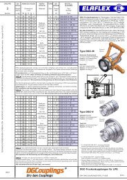
GRUPPE GE-WICHT1 WeightApprox.SCHLAUCH-GRÖSSEHoseSize≈BetriebsdruckWork. PressurePrüfdruckTest PressureUnterdruckmax. VacuumBiegeradiusBend. RadiusRollenlängeCoil LengthBESTELL-NUMMERPartNumberSection ≈ kg / m ID in. ID mm OD mm bar bar bar mm ≈ m TypeTECHNISCHE ÄNDERUNGEN VORBEHALTEN · NACHDRUCK UND KOPIEN NUR MIT UNSEREM EINVERSTÄNDNIS · Specifications subject to change without notice · Copyright <strong>ELAFLEX</strong>0,3 3⁄8" 10 200,8 70 40 LPG 10 * ) Flüssiggasschlauch 'Orangering', nach EN 1762. Für Propan,Butan und deren Gemische nach EN 589. Aufgrund der sehrdiffusionsarmen Innenschicht auch für viele gasförmige Medien0,4 1⁄2" 13 23 0,5 85 40 LPG 13 geeignet, z. B. Erdgas.0,6 3⁄4" 19 31 0,5 100LPG 190,8 1" 25 38 0,4 15040LPG 25(50)1,0 1¼ " 32 45 0,3 175(60)LPG 321,2 1½ " 38 52 25 40 0,2 200(80)LPG 382,0 2" 50 66 0,2 250 LPG 503,4 3" 75 93 – 450 40 LPG 754,3 4" 100 118 – 750 40 LPG 1007,9 6" 150 173 – 1200 30 LPG 150 ** )11,0 8" 200 228 – 1600 30 LPG 200 ** )Einsatz : Als Trommelschlauch für die Versorgung von Haushalten und Industrie betrieben,als Zapfstellenschlauch für die Autogas-Betankung von KFZ und Flurförderfahrzeugen, zurBefüllung und Entleerung von Kesselwagen, Tankwagen und Schiffen.Für spezielle Saug- / Druck-Anwendungsfälle kann auf Anfrage die Type LPGS mitEdelstahlwendel hergestellt werden.* ) Zur Beachtung : LPG 10 entspricht BUTAPAL 10, mit orangen Längsstreifen.Kennzeichnung : orange Markenringe alle 2,5 mtr. und normgerechte, fortlaufende,einvulkanisierte Prägebandstempelung in dauerhaft abriebfester Qualität:LPG 32 · D · EN 1762 · FLÜSSIGGAS · L.P. GAS · TEMPERATUR - 40° C + 70° C · DVGW – DG-4621 AU0049 · M · TRbF 131 · Ω · PN 25 BAR / WP 350 PSI · <strong>ELAFLEX</strong> GERMANY · · 2Q-13Application : As reel hose for supplies to domestic and industrial storage tanks, aspump hose for vehicle refuelling, for bulk loading and unloading from rail tankers, roadtankers and ships.For special suction / pressure operation needs the type LPGS with stainless steelhelix is available on request.* ) Please Note : LPG 10 corresponds to BUTAPAL 10, with longitudinal orange stripes.Marking : orange bands every 2,5 mtr.. Continuous, abrasion resistant embossing asspecifi ed in the EN standard 1762, as per example above.Einbindung und Prüfung: Für Flüssiggasschläuche dürfen nur Sicherheitsarmaturennach EN 14422 oder EN 14424 mit fester Einbindung verwendetwerden, siehe Beispiele. Die fachmännisch montierte, komplette Schlauchleitungist entsprechend EN 1762 einer Druck- und Leitfähigkeitsprüfung zuunterziehen.Nicht geeignet für Ammoniak.Stabiler und langlebiger Schlauchaufbau mit 2 dehnungsarmenTextilgeflechtseinlagen. Berstdruck > 100 bar. Temperaturbereich- 40° C bis + 70° C. (LT-Sonderausführung bis - 50° C kältebruchfest).DVGW-geprüft, Nr. DG-4621 AU 0049.Innen : NBR, schwarz, nahtlos extrudiert,elektrisch leitfähig, diffusionsarmFestigkeitsträger : Textilgeflechte mit 2 gekreuzten KupferlitzenAußen : Chloroprene (CR), schwarz, elektrisch leitfähig,schwer entflammbar, hoch abriebfest,ozon-, UV- und alterungsbeständigType LPG'Orange Band' Liquid Petroleum Gas hose to EN 1762. Forpropane, butane, and their mixtures to EN 589. As the hose liningis resistant to diffusion the hose is also suitable for natural gas.Not suitable for ammonia.Rugged and long-lasting construction with low textile braids.Permitted working pressure 25 bar, burst pressure > 100 bar.Temperature range - 40° C up to + 70° C. ( Special type LPG-LTdoes not crack down to - 50° C ). Approved by DVGW, approvalNo. DG-4621 AU 0049.Lining : Nitrile rubber (NBR), black,electrically conductive, diffusion resistantReinforcements : Textile braids with 2 crossed tinnedcopper strandsCover : Chloroprene (CR), black, electrically conductive,fl ame and abrasion resistant,ozone, UV and ageing resistantinnerhalb EU nach DGRL Kat. III − Sonderanfrage erforderlich** ) within EU acc. PED Cat III – special enquiry necessaryAssembly and tests : For L.P. Gas hoses only suitable safety fittings acc.to EN 14422 or EN 14424 must be used which can be mounted tightly, seeexamples below. According to EN 1762, hose assembling must include amandatory pressure and conductivity test.1 2 3 4 5Type M Type SVC - NPT Type SMC Type ACM (ACME) Type SFCLeitfähigkeit: 'OHM'-Type nach EN 1762. Elektrischer Widerstand R < 106 Ohm, gemessen zwischen den Schlaucharmaturen.Hierzu müssen <strong>bei</strong> der Armaturenmontage die metallischen Leiter nicht angeschlossen werden.Auf ausdrücklichen Kundenwunsch können die <strong>bei</strong>den eingear<strong>bei</strong>teten Kupferlitzenmit den Armaturen verbunden werden; auf diese Weise wird ein elektrischerWiderstand von R < 10² Ohm erzielt ('M'-Type nach EN 1762).Electrical conductivity: 'OHM'-Type according to EN 1762.Electrical resistance. R < 106 Ohm, measured in between hose end fittings.For the hose assembly the copper strands do not have to be connected to the fittings.At customerʹs request the two copper strands incorporated in the hose can be connectedto the hose fittings with resulting electrical resistance R < 10² Ohm ('M'-type according to EN 1762).2002Revision 9.2013LPG 16 Zapfschlauch für Flüssiggas-Zapfsäulen siehe umseitig––––LPG 16 Hose for L.P. Gas Dispensers see overleafFlüssiggasschlauch LPGLIQUEFIED PETROLEUM GAS HOSE LPG115
LPG 16 Zapfschlauch · LPG 16 Autogas HoseWeightApprox.GewichtSCHLAUCH-GRÖSSEHoseSizeBetriebsdruckWork. PressurePrüfdruckTest PressureUnterdruckVacuumBiegeradiusBend. RadiusRollenlängeCoil LengthBESTELL-NUMMERPartNumber≈≈ kg/m ID in. ID mm OD mm bar bar bar mm ≈ m Type0,5 5⁄8" 16 26 25 40 0,5 9040max.80LPG 16Type LPG 16 ist ein hoch flexibler Standard-Zapfschlauch für die Autogas-Betankung.Der weichmacherfreie Innengummi schließt Auswaschungen aus. Basierend auf demSlimline Zapfschlauch ( siehe S. 111 ), verfügt LPG 16 über eine schwarze, glatte Oberfl äche,geprickt und fortlaufende, Lasermarkierung in dauerhaft abriebfester Qualität :LPG 16 – EN 1762 · D · - 40° · Ω · PN 25 · M · <strong>ELAFLEX</strong> GERMANY · · 04.13Type LPG 16 is a highly fl exible standard Autogas hose for L.P. Gas dispensers. Theplasticiser-free lining guarantees that no components can be washed out. Based on theSlimline petrol pump hose ( see page 111 ), LPG 16 has a black, smooth surface, perforatedand a continuous, abrasion resistant laser marking as per example above.Druckverlustvon <strong>ELAFLEX</strong> LPGSchlauchleitungenLänge 5 mtr.DN 13 − DN 19( mit Isopar )–––––Pressure dropfor <strong>ELAFLEX</strong> LPGhose assemblieslength 5 mtr.DN 13 – DN 19( with Isopar )Druckverlust bar · Pressure drop bar –––––––→21,81,61,41,210,80,60,40,2LPG 13LPG 16LPG 1900 10 20 30 40 50Durchfl ussleistung Liter / Minute · Flowrate litres / minute –––––––→Zapfschlauch für Flüssiggas-Zapfsäulen. EntsprichtEN 1762 und TRbF 131. Für Propan, Butan und derenGemische nach EN 589.Hochflexibler und langlebiger Schlauchaufbau. Berstdruck> 100 bar. Temperaturbereich - 40° C bis + 70° C. DVGW geprüft,Nr. DG-4621 AU 0049.Innen : NBR, schwarz, nahtlos extrudiert,elektrisch leitfähig, diffusionsarm,weichmacherfreiFestigkeitsträger : dehnungsarme Textilgeflechte mitelektrisch anschließbaren gekreuztenverzinnten KupferlitzenAußen : CR, schwarz, glatt, geprickt,elektrisch leitfähig, hoch abriebfest,hoch alterungsbeständigTypeLPG 16Hose for L.P. Gas dispensers. Meets EN 1762 and TRbF 131.For propane, butane and other L.P. gases.Highly flexible and long-lasting construction. Burst pressure> 100 bar. Temperature range - 40° C up to + 70° C. DVGWapproval No. DG-4621 AU 0049.Lining : NBR, black, seamlessly extruded,electrically conductive, low diffusion,plasticiser-freeReinforcements : low tensile textile braids withcrossed tin-plated copper strandselectrically connectableCover : CR, black, smooth, perforated,electrically conductive, highly abrasionresistant, highly ageing resistantDas komplette System für LPG-Zapfsäulen · The complete kit for LPG dispensersLPG Zapfventil ZVG 2siehe Katalogseite 561––––LPG nozzle ZVG 2see catalogue page 561LPG 16 - EN 1762 · D · -40° · Ω · PN 25 · M · <strong>ELAFLEX</strong>GERMANY · 04.13GERMANY · 04.13Schlaucharmaturen wiederverwendbaroder nicht wiederverwendbars. Katalogseiten 203 / 205,Information 4.03––––Hose couplingsreusable or non reuseablesee catalogue pages 203 / 205,Information 4.03AbreißkupplungARK 19 Mod. 2unter Druck wieder montierbarsiehe Katalogseite 563––––Safety Break couplingARK 19 Mod. 2reconnectable under pressuresee catalogue page 563LPG 16 - EN 1762 · D · -40° · Ω · PN 25 · M · <strong>ELAFLEX</strong> GERMANY · 04.13LPG 16 - EN 1762 · D · -40° · Ω · PN 25 · M · <strong>ELAFLEX</strong>LPG 16 - EN 1762 · D · -40° · Ω · PN 25 · M · <strong>ELAFLEX</strong> GERMANY · 04.13Zapfventil-Tasche NB-LPGfür ZVG 2, ZVG 1 etc.––––Nozzle Boot NB-LPGfor ZVG 2, ZVG 1 and nozzlesof other manufacturersSortentülle CS 16 orangesiehe Katalogseite 211––––Colour Sleeve CS 16 orangesee catalogue page 211GERMANY · 04.13LPG 16 - EN 1762 · D · -40° · Ω · PN 25 · M · <strong>ELAFLEX</strong>116Knickschutz KS 16siehe Katalogseite 211––––Anti Kinking Sleeve KS 16see catalogue page 211GERMANY · 04.13Zapfschlauch LPG 16siehe oben––––Autogas hose LPG 16see aboveLPG 16 - EN 1762 · D · -40° · Ω · PN 25 · M · <strong>ELAFLEX</strong>
GRUPPE GE-WICHT1 WeightApprox.SCHLAUCH-GRÖSSEHoseSizeBetriebsdruckWork. PressurePrüfdruckTest PressureUnterdruckmax. VacuumBiegeradiusBend. RadiusRollenlängeCoil LengthAusführungDesignBESTELL-NUMMERPartNumberSection ≈ kg ID in. ID mm OD mm bar bar bar mm ≈ m Form TypeTECHNISCHE ÄNDERUNGEN VORBEHALTEN · NACHDRUCK UND KOPIEN NUR MIT UNSEREM EINVERSTÄNDNIS · Specifications subject to change without notice · Copyright <strong>ELAFLEX</strong>0,4 1⁄2" 13 22– 70CHD 130,6 3⁄4" 19 31 – 100 CHD 190,8 1" 25 37 – 150 CHD 2516 2540 D1,0 1¼ " 32 44 – 175 CHD 321,2 1½ " 38 51 – 200 CHD 382,0 2 50 66 – 350 CHD 501,0 1" 25 370,9 90CHS 251,2 1¼ " 32 44 0,9 100 CHS 321,4 1½ " 38 51 0,9 110 CHS 382,1 2" 50 66 16 25 0,9 140 40 SD CHS 502,7 2½ " 63 79 0,9 180 CHS 633,3 3" 75 91 0,8 200 CHS 754,7 4" 100 116 0,8 400 CHS 1009,8 6" 150 172 10 16 0,8 800 30 SD (CHS 150)Einsatzbereich: Hochflexibler Schlauch für über 75 % aller Industrie-Chemikalien. Einsatzgrenzenin Hinblick auf Medien, Konzentration, Temperatur siehe Beständigkeitsübersicht.Elektrisch leitfähige Montage über Innen- und Außenschicht ohne metallischen Anschluss.Erfüllt die Anforderungen der EN 12115 und TRbF 131/2.Kennzeichnung: Normgerechte lila Markenringe alle 1,0 mtr. (CHS 25 + 50 alle 0,5 mtr.) undfortlaufende, normgerechte Prägebandstempelung :CHS 50 · EN 12115 EPDM · SD · Ω /T · CHEMICALS · TRbF 131 · Ω · PN 16 BAR · <strong>ELAFLEX</strong> 1Q-13Application: Highly fl exible hose for more than 75 % of all industrial chemicals. Limits regardingmedium, concentration, temperature see resistance chart. Electrically conductive connection viatube or cover without metallic contact. Meets EN 12115 and safety regulations TRbF 131/2.Marking: Lilac bands every 1,0 mtr. (CHS 25 + 50 every 0,5 mtr.) and continuous, vulcanisedembossed stamping as per example.0,3 3⁄8" 09 18– 50LMD 090,4 1⁄2" 13 22 – 70 LMD 1316 2540 D0,6 3⁄4" 19 31 – 100 LMD 190,8 1" 25 37 – 150 LMD 251,0 1" 25 370,9 90LMS 251,2 1¼ " 32 44 0,9 100 LMS 321,4 1½ " 38 51 0,9 110 LMS 382,1 2" 50 66 16 25 0,9 140 40 SD LMS 502,7 2½ " 63 79 0,9 180 LMS 633,3 3" 75 91 0,8 200 LMS 754,7 4" 100 116 0,8 400 LMS 1009,8 6" 150 172 10 16 0,8 800 30 SD (LMS 150)Einsatzbereich: Hochfl exibler Schlauch für technische Lösungsmittel, auch für Wasser undwasserlösliche Farben geeignet. Elektrisch leitfähige Montage über Innen- und Außenschichtohne metallischen Anschluss. Erfüllt EN 12115 und TRbF 131/2.Um die Gefahr von Verfärbungen empfindlicher Flüssigkeiten zu vermeiden, sollten dieSchläuche vor Inbetriebnahme mit dem Durchfl ussmedium gut durchgespült werden.Kennzeichnung: Blaue Markenringe alle 1,0 mtr. (LMS 150 alle 2,5 mtr.) und normgerechte,fortlaufende Prägebandstempelung:LMS 50 · EN 12115 NBR 2 · SD · Ω /T · SOLVENTS · TRbF 131 · Ω · PN 16 BAR · <strong>ELAFLEX</strong> 1Q-13Application: Highly fl exible hose for technical solvents, also for water and water soluablepaints. Electrically conductive connection via tube or cover without metallic contact. MeetEN 12115 and safety regulations TRbF 131/2.In order to avoid danger of discolouration of critical liquids, the hoses should be well fl ushedwith the medium before <strong>bei</strong>ng put into operation.Marking: Blue bands every 1,0 mtr. (LMS 150 every 2,5 mtr.) and continuous vulcanisedembossed stamping as per example.Chemieschlauch 'Lilaring' für Chemikalien, Säuren, (außerkonzentr. oxidierende Säuren), Laugen, Salzlösungen, Alkohole,polare Lösungsmittel, Acetate, Aldehyde, Ester, Ketone,Phenol, Heißwasser (Kühlwasser), Heißluft nicht ölhaltig.Temperaturbereich - 40° bis + 100° Celsius (medienabhängig).Offenes Ausdämpfen bis 150° C / max. 30 min. zulässig.Nicht geeignet für aliphatische, aromatische, halogenierte Kohlenwasserstoffe,Kraftstoffe, Mineralöle, Chlor, Chloride, Ether, Teeröle.Innen : EPDM, schwarz, glatt, nahtlos, leitfähigFestigkeitsträger : TextilgeflechteType CHS zusätzl. mit verzinkter StahldrahtwendelAußen : EPDM, leitfähig, ozon- und UV-beständigfür DruckbetriebType CHDfor pressure onlyfür Saug und DruckType CHSsuction + dischargeEN 12115 · EPDM · TYPE CHD 25 · DEN 12115 · EPDM'Lilac Band' multi purpose hose for chemicals, acids (except forconcentr. oxidising acids), alkalis, salt solutions, alcohols, polarsolvents, acetates, aldehydes, ester, ketones, hot cooling water,hot air, not oily. Temperature range - 40° up to + 100° Celsius(depending on medium). Open steam cleaning up to 150° C / max. 30 min.Not suitable for aliphatic, aromatic and halogenated hydrocarbons,fuels, chlorine, chloride, ether, tar oils and oxidising acids.Lining : EPDM, black, smooth, seamless, conductiveReinforcements : Textile braidsType CHS additionally with galvanised steel helixCover : EPDM, conductive, resistant against ozoneLösungsmittel-Schlauch 'Blauring' für die meisten Lösungsmittel,Farben (auch wasserlöslich), Wasserlacke und Disper sonen,Mineralölprodukte, Alkohle, Aldehyde, Ester und Ketone. Im Kurzzeitbetriebauch geeignet für aromatische und chlorierte Kohlenwasserstoffe.Weitere Angaben siehe Beständigkeitsübersicht.Temperaturbereich von - 20° bis + 80° C, kurzzeitig bis + 100° C.Neuer Innengummi: keine Wasserempfindlichkeit, verminderteVerfärbungsgefahr. Offenes Ausdämpfen bis max. 30 Min. / + 130° C.Innen : Blauer NBR spezial, glatt, nahtlos,antistatisch, leitfähigFestigkeitsträger : TextilgeflechteType LMS zusätzl. mit verzinkter StahldrahtwendelAußen : NBR/PVC - Spezial-Compound, leitfähig.Ab DN 63 Chloroprene, schwarz, leitfähigfür DruckbetriebType LMDfor pressure onlyfür Saug und DruckType LMSsuction + dischargeForm DForm DForm SDLMS 25 · EN 12115 · NBR 2 · D · SOLForm SDLMS 50 · EN 121Solvent hose 'Blue Band' for most solvents, paints (also waterbased), water lacquer, petroleum products, alcohols, aldehydes,esters and ketones. In short term operation also suitable for aromaticand chlorinated hydrocarbons. Further details see resistance chart.Temperature range - 20° up to + 80° C, short term up to + 100° C.New lining: water resistant. Lower risk of discolouration. Opensteam cleaning up to 130° C / max. 30 min.Lining : NBR special compound, blue, smooth,seamless, antistatic, conductiveReinforcements : Textile braidsType LMS additionally with galvanised steel helixCover : NBR / PVC special compound, conductive.From DN 63 chloroprene (CR), black, conductive2004Revision 1.2013Besserals dieNormBetriebsdruck nach Norm = 10 bar. Wir liefern 16 bar!Nach EN 12115 sind einfache Litzen und eine dünneStahlwendel erlaubt. Wir liefern zwei gefl ochtene Einlagenund dickere Drahtstärken nach Militärnorm VG 95 955.Chemie- und LösungsmittelschläucheHOSES FOR CHEMICALS AND SOLVENTS117
Tabelle zur Bestimmung des Schlauchdurchmessers · Chart to Determine the Hose DiameterQDurchflussmengeFlowrateDiese Tabelle soll Ihnen <strong>bei</strong> der Wahl der erforderlichen Schlauchgröße'ID' je nach gewünschter Durchflussmenge behilfl ich sein.Bei den angegebenen Werten ist der durch die Reibung innerhalbdes Schlauches auftretende Druckverlust nicht berücksichtigt.Zur Bestimmung des Druckverlustes dient die Tabelle auf Seite 104.This chart shall assist you to choose the necessary hosesize 'ID' depending on the flow quantity. The values donot take into consideration the pressure drop caused bythe friction within the hose.To establish the pressure drop see the chart on page 104.l/minm3/h1000090008000700060005 0004 000600500400350IDSchlauchgrößeinnerer DurchmesserFlowrateinner diameter3 0002 5002 0001 5001 00020015010090807060mm300 12"250 10"200 8"150 6"125 5"in.V *)DurchflussgeschwindigkeitFlow velocity11,590080050100 4"270060050040030025020015012010090804030201510987658075 3"63 2¹¼2"50 2"45 1³¼4"4038 1¹¼2"3532 1¹¼4"25 1"19 ¾"1615 ⅝"13 ½"10m/s2,533,54567891070604504035302532BEISPIEL:Bestimme den inneren Durchmesser eines Schlauches 'ID'.Als Durchfl ussmenge 'Q' werden 250 Liter je Minute (l/min) gefordert.Die Durchflussgeschwindigkeit 'V' soll aus Sicherheitsgründen 4 Meterje Sekunde (m/s) nicht überschreiten.LÖSUNG:Die gestrichelte Linie zwischen Q und V ergibt ID, in diesem Fall38 mm innerer Durchmesser als richtige Größe des Schlauches.EXAMPLE:Determine the inner diameter of a hose 'ID'. The fl owrate 'Q' is 250 litres per minute (l/min). The fl ow velocity'V' is not to exceed 4 metres per second(m/s) for safetyseasons.SOLUTION:The dotted line between Q and V gives the correct ID ofthe hose, in this case 38 mm.201*) ZUR BEACHTUNG:Bei Gefahr von elektrostatischen Aufl adungen sollten nachstehendeDurchfl ussgeschwindigkeiten nicht überschritten werden:*) PLEASE NOTE:In case of danger of electrostatic charges the followingfl ow velocities should not be exceeded:1510ID 25 mm = 5 m/sID 50 mm = 3,5 m/sID 100 mm = 2,5 m/sID 200 mm = 2 m/sIn der Praxis werden diese Durchfl ussgeschwindigkeiten teilweiseerheblich überschritten, wenn z. B. durch aufl adungsverhinderndeTreibstoffzusätze oder sichere Erdung bzw. Beruhigungsstreckenkeine Gefahren durch elektrostatische Aufl adungen bestehen.ID 25 mm = 5 m/sID 50 mm = 3,5 m/sID 100 mm = 2,5 m/sID 200 mm = 2 m/sIn practice these velocities can be exceeded considerablyif there is no danger of electrostatic charges when e.g.a safe earthing is applied of fuel additives are used thatprevent the charging.118
GRUPPE GE-WICHT1 WeightApprox.SCHLAUCH-GRÖSSEHoseSizeBetriebsdruckWork. PressurePrüfdruckTest PressureUnterdruckmax. VacuumBiegeradiusBend. RadiusRollenlängeCoil LengthBESTELL-NUMMERPartNumberSection ≈ kg/m ID in. ID mm OD ≈ mm bar bar bar mm ≈ m TypeTECHNISCHE ÄNDERUNGEN VORBEHALTEN · NACHDRUCK UND KOPIEN NUR MIT UNSEREM EINVERSTÄNDNIS · Specifications subject to change without notice · Copyright <strong>ELAFLEX</strong>0,4 1⁄2" 13 220,6 100EFD 130,65 3⁄4" 19 31 16 25 0,5 125 40 EFD 190,9 1" 25 37 0,4 150 EFD 25Andere Nennweiten siehe Type ELAFLON PLUS FEP, Katalogseite 125––––For other dimensions please refer to Type ELAFLON PLUS FEP, catalogue page 125Einsatzbereich: Als Druckschlauch für Abgabeeinrichtungen und Faßpumpen im Vollschlauchsystemund Leerschlauchsystem. Auch als Trommelschlauch geeignet, wennder Innendruck ständig mindestens 0,5 bar beträgt, damit der Schlauch nicht einknickt.Kennzeichnung: Blau-weiß-rote Ringe und normgerechte fortlaufende Prägestempelung.EFD 25 · EN 12115 · ELAFLON · D · Ω · UNIVERSAL · 100° C · TRbF 131 · PN 16 BAR ·<strong>ELAFLEX</strong> GERMANY · · 4Q-13Application: As pressure hose for discharge and barrel pumps in wet and dry hose systems.Also suitable as reel hose provided the inner pressure reaches min. 0,5 bar to avoid kinking.Marking: Hose is marked with blue-white-red bands and embossed continuously.0,8 3⁄4" 19 311,3 1¼ " 32 44 16 25 0,9 125 40 EFS 3290EFS 191,0 1" 25 37 100 EFS 251,5 1½ " 38 51 150 EFS 382,2 2" 50 66 200 EFS 50Andere Nennweiten siehe Type ELAFLON PLUS FEP, Katalogseite 125––––For other dimensions please refer to Type ELAFLON PLUS FEP, catalogue page 125Einsatzbereich: Als Saug- / Druckschlauch zum Befüllen und Entleeren von Fässern,Behältern, Tank- und Kesselwagen und Tankschiffen. Die kräftige Stahlwendel sorgtdafür, dass der Schlauch <strong>bei</strong> Saugbetrieb und Schwerkraftabgabe <strong>bei</strong> engen Biegeradienrund bleibt.Kennzeichnung: Blau-weiß-rote Ringe und normgerechte fortlaufende Prägestempelung.EFS 50 · EN 12115 · ELAFLON · SD · Ω · UNIVERSAL · 100° C · TRbF 131 · PN 16 BAR ·<strong>ELAFLEX</strong> GERMANY· · 4Q-13Application : As suction and discharge hose for barrels, containers, tank wagons andtankers. The steel helix ensures that the hose keeps in shape during suction and gravityoperations.Marking: Hose is marked with blue-white-red bands and embossed continuously.Reinigung und Ausdämpfen: Die glatte ELAFLON-Auskleidung sorgt für eine schnelleRestentleerung, erleichtert die Reinigung und ermöglicht das 'offene' Ausdämpfen bismax. 130° C / 30 min. Bitte unbedingt Ausdämpfungshinweise auf Seite 121b beachten.––––Cleaning and steaming out: The smooth ELAFLON tube ensures a quick drainingof rests, eases the cleaning and enables the 'open' steaming out up to a maximumof 130° Celsius / min. Please take notice of the hints at steaming out on page 121b.ELAFLON ® Universalschlauch 'Blau-Weiß-Rot' für alle ChemieundMineralölprodukte sowie Lösungsmittel gemäß umseitigerBeständigkeitsübersicht. Ideal für Nahrungs- und Genussmittel,Trinkwasser usw. Temperaturbereich - 30° bis + 100° C.Erfüllt die Anforderungen der EN 12115.Ausdämpfbar für Reinigung bis 130° C über max. 30 Minuten(offenes System).Innen : Fluorpolymer ELAFLON, weiß, glatt,glänzend, nicht auslaugend,nicht ausfärbend, nicht verhärtend,diffusionsarm. Nicht elektrisch leitfähigFestigkeitsträger : Textilgeflechte, Type EFS zusätzlich mitverzinkter StahlwendelAußen : Chloroprene ( CR ), schwarz, glatt,leitfähig, lichtrissbeständig,schwer entflammbarohne WendelType EFDwithout helixmit StahlwendelType EFSwith steel helix<strong>ELAFLEX</strong> GERMANYEFS 50 ∙ SD ∙ PN 1ELAFLON ® 'Blue-White-Red' universal hose for all chemical andpetroleum based products as well as solvents (see resistancechart overleaf). Ideal for foodstuff, drinking water etc. Temperaturerange from - 30° to + 100° C.Corresponds to EN 12115.Steaming out for cleaning and sterilisation permissable up to130° C max. 30 minutes (open system).Lining : Fluoropolymer ELAFLON, white, smoothbore. No liquid soluble matter,non - discolouring and non - hardening.Non - electrically conductive.Reinforcement : Textile braids with tinned copper strands.Type EFS additionally with galvanisedsteel helixCover : Chloroprene ( CR ), black, smooth,conductive. Ozone resistant and flame proof.1996Revision 10.2013ELAFLON-SchläucheELAFLON HOSES119
Beständigkeitsübersicht für 'ELAFLON' · Chemical Resistance Chart for 'ELAFLON'Medien <strong>bei</strong> normaler Temperatur * )Bei Gemischen alle Komponenten beachten––––Fluids at normal temperature * )All components of mixtures must be consideredAldehydeAldehydesAliphatische Kohlenwasserstoffe wie Benzin, Diesel,Heizoel, Petroleum, Rohöl, Schmieröle, FetteAliphatic hydrocarbons as gasoline, diesel,fuel oil, petroleum, crude oil, lubricating oils, greaseAlkohole wie Ethanol, Methanol, IsopropylalkoholAlcohols, ethanol, methanol, isopropylalcoholAmeisensäureFormic acidAmide wie DimethylformamidAmides as dimethyl formamideAmine, primäre aliphat. wie Butylamin,Ethylendiamin, PropylaminAmines, primary aliphatic such as Butylamine,ethylenediamine, propylamineLeerschlauch /KurzzeiteinsatzDry hose deliverytemporary serviceAAAAVollschlauch /LangzeiteinsatzWet hose deliverylong time service23° C A A23° C C CAmine, sekundäre, tertiäre und cyclische wie Triethylamin,Anilin, Morpholin, Pyridin, Diethylamin u. Pyrrolidin 1) 23° CAmines, secondary, tertiary & cyclic such as Triethylamine,C CAniline, Morpholine, Pyridine, Diethylamine + Pyrrolidine 1)Ammoniak wässrig, FlüssigdüngerAmmonia aqueous, liquid fertilizersAromatische Kohlenwasserstoffe wie Benzol, Toluol, XylolAromatic hydrocarbons as benzene, toluene, xyleneChlor trocken, Chlor feuchtChlorine gas dry, chlorine gas wetChlorsulfonsäureChlorosulfonic acidChromsäureChromic acidChlorierte Kohlenwasserstoffe wie Methylenchlorid,Tetrachlorkohlenstoff, Perchlorethylen, TrichlorethylenChlorinated hydrocarbons as methylene chloride, carbontetrachloride, perchloroethylene and trichloroethyleneEssigsäureAcetic acidEster, Acetate, EtherEster, acetates, etherFluorkohlenwasserstoffe (FCKW) wie Trichlormonofluormethan,Dichlordifluormethan (Freon, Frigen, Arcton)Fluoro hydrocarbons as trichlormonofl uoromethane,dichlordifl uormethane (Freon, Frigen, Arcton)Flusssäure, Fluorwasserstoffsäure konz. 35° CHydrofloric acid conc. 35° CGlykole, Enteisungsflüssigkeiten, FrostschutzmittelGlycol, defrosting fl uids, anti-freezing fl uidsKalilauge, Natronlauge, Reinigungslaugen 100° CPotassium hydroxide, sodium hydroxide, cleaning alkalis 100° CKetone wie Aceton, Methylethylketon, CyclohexanonKetones as acetone, methyl ethyl ketone, cyclohexanonKraftstoffe mit Aromaten-, Ether-und MethanolzusätzenGasoline with aromatic, ether and methanol additivesKresol, Phenol, TeeröleCresol, phenol, tar oilMilch, pflanzliche und tierische Öle und FetteMilk, vegetable and animal oils and fatsOxalsäureOxalic acidPhosphorsäure konz.Phosphoric acid conc.Salpetersäure 65 %Nitric acid 65 %Salpetersäure rauchendNitric acid smokingSalzsäure konz.Hydrochloric acid conc.Schwefelsäure 96 %Sulfuric acid 96 %Schwefelsäure rauchend (Oleum 20 %)Sulfuric acid (Oleum 20 %)Spirituosen, Wein, Bier, Trinkwasser, Säfte, PharmakaSpirits, wine, beer, drinking water, fruit juices, pharmaceuticsAAHAAAAAAAAAAAAAAAACAAAABAAABAHBAAAAAAAABAAAAAHCAAHAZEICHENERKLÄRUNGA =B =C =gut geeignet. Medium wird nichtkontaminiertkurzzeitig geeignet. Bei längerem Kontaktwird die Auskleidung langsam angegriffennicht geeignet : Auskleidung wird schnellangegriffen und in wenigen Tagen zerstörtH = Bitte mit Betriebsbedingungen anfragen1) Gelegentlicher Kurzzeiteinsatz möglich, wennsofort nach Entleerung Innenreinigung erfolgt.* ) TEMPERATURGRENZEN – BITTE BEACHTEN :Bei Medien ohne besondere Temperaturanga<strong>bei</strong>st unter 'normaler Temperatur' das Füllen undEntleeren dieser Medien <strong>bei</strong> den üblichen Temperaturenbis + 65° C entsprechend der EN 12115 zuverstehen. Der volle Temperatureinsatzbereich desSchlauches von 100° Celsius kann für die meistenMedien im Leerschlauchbetrieb ausgenutzt werden.In Zweifelsfällen bitte rückfragen.WICHTIGER VORBEHALT :ELAFLON ist ein Mischpolymerisat aus dreiFluor-Kunststoff-Komponenten, von denen zweivoll fl uoriert sind. Die Beständigkeitsangabenberuhen auf Aussagen des Rohstoffherstellers.Sie entsprechen dem Stand der Technik Jan. 1990und informieren über Anwendungsmöglichkeiten.Eine rechtliche Zusicherung von Eigenschaftenoder die Zusicherung ihrer Eignung für konkreteEinsatzzwecke kommt ihnen nicht zu. Wir stellengern Folienmuster für Versuche zur Verfügung.Detaillierte Angaben sieheBeständigkeitsliste <strong>ELAFLEX</strong> - Schläuche––––Details seeResistance Chart <strong>ELAFLEX</strong> HosesLegendA =B =C =H =good, fl uid has little or no effect,medium does not get contaminatedsuitable for short term use. Lining willbe slowly attacked through longercontactnot suitable : lining is quickly attackedand destroyed in a few daysPlease inquire specifying operatingconditions1) Occasional temporary service possibleprovide hose is cleaned inside promptly afterit is emptied.* ) Temperature range – Please observeIf no special temperature is stated for the media, as'normal temperature' for fi lling and discharge thestandard temperature for the media up to + 65° Caccording to EN 12115 can be considered. The fulltemperature range up to 100° C can be used for mostmedia but only for dry hose deliveries. In case ofdoubt please ask for information.IMPORTANT RESERVATIONELAFLON is a polymer of three fluorine syntheticcomponents of which one is not fully consolidated.The details for the resistance are based on informationfrom the producer and cannot be guaranteed by us.They meet today's technical standard and informabout the range of application. They do not representa legal assurance about properties or their suitabilityfor a concrete application. We can provide foil samplesfor test purposes.120
GRUPPE GE-WICHT1 WeightApprox.SCHLAUCH-GRÖSSEHoseSizeBetriebsdruckWork. PressurePrüfdruckTest PressureUnterdruckmax. VacuumBiegeradiusBend. RadiusRollenlängeCoil LengthAusführungDesignBESTELL-NUMMERPartNumber≈Section kg / m ID in. ID mm OD mm bar bar bar mm ≈ m Form Type0,3 ½ " 13 220,6 100UTD 130,5 ¾ " 19 31 0,5 125 UTD 190,6 1" 25 37 16 25 0,4 150 40 D UTD 25Blau-weiß-blau-Universalschläuche für fast alle fl üssigen undpastösen Chemie- und Mineralölprodukte sowie Lösungsmittel.Temperaturbereich - 30° bis + 100° C in Abhängigkeit vom Medium.Ausdämpfbar für Reinigung und Sterilisation bis 130° C für max.30 min (offenes System).Erfüllen die Anforderungen nach EN 12115, TRbF 131.TECHNISCHE ÄNDERUNGEN VORBEHALTEN · NACHDRUCK UND KOPIEN NUR MIT UNSEREM EINVERSTÄNDNIS · Specifications subject to change without notice · Copyright <strong>ELAFLEX</strong>0,8 1¼ " 32 44 0,4 175 (UTD 32)1,0 1½ " 38 51 0,3 225 (UTD 38)Einsatzbereich: Druckschlauch PN 16 für Abgabeeinrichtungen, stationäre Anlagen undFasspumpen im Voll- und Leerschlauchbetrieb. Auch als Trommelschlauch geeignet, wennder Innendruck ständig mindestens 0,5 bar beträgt, damit der Schlauch nicht einknickt.Kennzeichnung: Blau-weiss-blaue Ringe alle 0,5 mtr. und fortlaufende Prägestempelung:UTD 38 · EN 12115 UPE · D · Ω/T · UNIVERSAL · TRbF 131 · PN 16 BAR 1Q-13Application: Pressure hose PN 16 for discharge in wet and dry hose usage. Alsosuitable as reel hose provided the inner pressure reaches min. 0,5 bar to avoid kinking.Marking: Blue-white-blue bands every 0,5 mtr. Continuous embossing as per example.0,6 ¾ " 19 311,2 1½ " 38 51 150 UTS 3816 25 0,940 SD1,8 2" 50 66 200 UTS 5090UTS 190,8 1" 25 37 100 UTS 251,0 1¼ " 32 44 125 UTS 322,3 2½ " 63 79 250 (UTS 63)2,6 3" 75 91 300 UTS 754,2 4" 100 116400 UTS 1005,5 5" 125 145600(UTS 125)10 15 0,8308,4 6" 150 172 900 (UTS 150)Einsatzbereich : Saug- / Druckschlauch zum Befüllen und Entleeren von IBC's,Fässern, Tank- und Kesselwagen, Tankschiffen sowie in stationären Anlagen.Die kräftige Stahlwendel sorgt dafür, dass der Schlauch auch <strong>bei</strong>m Saugbetrieb und <strong>bei</strong>Schwerkraftabgabe in engen Biegeradien rund bleibt.Kennzeichnung : Blau-weiss-blaue Ringe alle 0,5 mtr. und fortlaufende Prägestempelung:UTS 50 · EN 12115 UPE · SD · Ω/T · UNIVERSAL · TRbF 131 · PN 16 BAR 1Q-13Application: Suction and discharge hose for IBC's and barrels, rail tankers, tankersand fixed installations. The strong steel helix ensures that the hose maintains its shapeduring suction and gravity operations.Marking: Blue-white-blue bands every 0,5 mtr. Continuous embossing as per example.1,8 2" 50 652,2 2½ " 63 78 180 UTL 6310 16 0,840 SD2,9 3" 75 90 200 UTL 753,9 4" 100 116 275 UTL 100Einsatzbereich : 'Universal-Tankschlauch Leicht' PN 10, bevorzugt zum Entladenvon Tankwagen sowie <strong>bei</strong> Einsätzen, in denen eine besondere Flexibilität und leichteBiegekräfte gefordert werden. Der angegebene Biegeradius ist ein Sicherheitswert.Der Schlauch läßt sich, ohne äußerlich einzuknicken, auch stärker biegen; die Innenauskleidungaus UPE würde jedoch da<strong>bei</strong> langfristig leiden.Kennzeichnung : Blau-weiss-blaue Ringe alle 1 mtr. und fortlaufende Prägestempelung :UTL 50 · EN 12115 UPE · SD · Ω/T · UNIVERSAL · TRbF 131 · PN 10 BAR 1Q-13Application: Lightweight tanker hose PN 10 suitable i.e. for unloading of tank wagonsand for applications where special fl exibility and easy handling is required.The mentioned bending radius is a safety value. Without visual signs of kinking, the hosemight be bent further; if long time practice the UPE tube will have a reduced service life.Marking: Blue-white-blue bands every 1 mtr. Continuous embossing as per example.150Innen : Ultrahochmolekulares Polyethylen UPE, weiß mitspiralisiertem Leitstreifen, glatt, abriebfest,nicht ausfärbend, leitfähig (Ω/T)Festigkeitsträger : TextilgeflechteType UTS zusätzlich mit verzinkter StahlwendelAußen : EPDM (EPT), schwarz, leitfähig, ozon- undUV-beständig, schwer entflammbarohne WendelType UTDwithout helixBlue-white-blue universal tank hoses for almost all liquid andpasty chemical and petroleum based products and solvents.Temperature range - 30° up to + 100° C depending on medium.Steaming out for cleaning and sterilisation permissable up to130° C up to max. 30 minutes (open ends).Meets EN 12115 and German safety standard TRbF 131.Lining : Ultra high molecular polyethylene UPE, white,with conductive OHM spiral stripe, smoothbore, abrasion resistant, no discoloration,conductive ( Ω /T)Reinforcement : Thermoplast braidsType UTS additionally with galvanised steel helixCover : EPDM (EPT), black, conductive,zone resistant, UV resistant, fl ame resistantUTL 50 Innen : Ultrahochmolekulares Polyethylen UPE,weiß mit spiralisiertem Leitstreifen, glatt,abriebfest, nicht ausfärbend, leitfähig ( Ω /T ).Festigkeitsträger : Kunststoffgeflechte, Doppelwendel ausverzinktem StahldrahtAußenΩmit StahlwendelType UTSwith steel helixΩType UTLΩForm DForm SD: EPDM (EPT), schwarz, mit Spezial-Einschnürungen,elektrisch ableitfähig, ozon- und UVbeständig,schwer entflammbarLining : Ultra high molecular polyethylene UPE,white, with spiral conductive stripe, smoothbore, abrasion resistant, no discoloration,conductive ( Ω /T)Reinforcement : Thermoplast braids, galvanised double steel helixCover : EPDM (EPT), black, smooth surface withcorrugations, conductive, ozone resistant,UV resistant, fl ame resistant2002Revision 2.2013Innen weiß für saubere Medienund trotzdem OHM-leitfähig für die Sicherheit—Conductive white tube for clean media + safetyUniversal-Tankschläuche UTD, UTS, UTLUNIVERSAL TANK HOSES UTD, UTS, UTL121a
Universal-Tankschläuche UTD, UTS, UTL · Universal Tank Hoses UTD, UTS, UTLKennfarben nach EN 12115 : blau-weiß-blauColour coding according EN 12115 : blue-white-blueChemische Beständigkeit – nicht geeignet für:Chemical resistance – not suitable for :Brom, Bromkohlenwasserstoff-Verbindungen, Chlor, Chlorsulfonsäure, Fluor und starkoxidierende Säuren wie konzentrierte Salpetersäure, rauchende Schwefelsäure (Oleum).Einzelheiten siehe Beständigkeitsübersicht. In Zweifelsfällen bitte rückfragen.Bromine, brominated hydrocarbons, chlorine, chlorosulfonic acid, fl uorine and strongly oxidisingacids such as conc. nitric acid, smoking sulfuric acid (oleum). For details see chemicalresistance chart. If in doubt, please ask our sales department.Auslaugbare Substanzenaus Innenauskleidung oder ZwischenschichtLeaching-out of substancesfrom lining or intermediate layerFarbliche Beeinflussung reiner MedienDiscolouring of pure mediaNeinNoNein – kritische Medien wie z.B. Toluol und Aceton werden auch im Vollschlauchbetrieb nichtverfärbtNo – critical media such as toluene and acetone show no perceptible discolouring of the conveyedproduct, even if the hose is kept full (wet hose usage).Innenschicht entspricht Lebensmittelgesetzenfür Nahrungs- und GenussmittelLining complies with foodstuff regulationsEntspricht den Anforderungen der FDA und USP Class VI.Erfüllt die Anforderungen der Kunststoffverordnung 10 / 2011 EU und deren Ergänzungen und istsomit konform mit der aktuell gültigen deutschen Bedarfsgegenständeverordnung und derenÄnderungen/Ergänzungen.Corresponds to the requirements of the FDA and USP Class VI.Fulfi lls requirements of regulation EU No 10/2011 for plastics in food contact.Schmelzpunkt der AuskleidungMelting point of lining material133 − 135° Celsius133 – 135° CelsiusTemperatureinsatzgrenzeMaximum operating temperatureMaximal 100° Celsius (in Abhängigkeit vom Medium)Max. 100° Celsius (depending on medium)Reinigung / AusdämpfenCleaning / steaming outDie glatte, antiadhäsive UPE Auskleidung ermöglicht gute Restentleerung und einfacheReinigung <strong>bei</strong> Medienwechsel. Alle in der Praxis üblichen Reinigungs- und Spülmittel könneneingesetzt werden. Das 'offene' Ausdämpfen und Sterilisieren ist möglich mit Sattdampftemperaturbis 130° C und bis zu 30 Minuten. Zur Reinigung keine Dampfl anzen benutzen.Der Dampfstrahl kann durch örtliche Überhitzung die Innenauskleidung schmelzen unddadurch die Schlauchleitung zerstören.The smooth, 'non-stick' UPE lining allows good drainage and easy cleaning whenchanging medium. All commercially used cleaning and fl ushing liquids can be used. 'Open'steaming out and sterilisation is possible with saturated steam up to 130° C for max. 30 minutes.Do not use steam nozzles which can destroy the tube by localised overheating.HandlichkeitHandlingUTD und UTS: gut fl exibel. UTL : sehr gut fl exibel, geringer Kraftaufwand <strong>bei</strong>m Biegen.UTD and UTS: good fl exibility. UTL: very good fl exibility, low required bending forces/radii.Montage / Selbstmontage von SchlaucharmaturenAssembly / self assembly of hose fi ttingsAlle nach EN 14420 genormten, handelsüblichen Chemie-Schlaucharmaturen können montiertwerden. Für die fachgerechte Montage werden <strong>ELAFLEX</strong> SPANNLOC- bzw. SPANNFIX-Sicherheitsklemmen empfohlen (siehe auch Katalog, Gruppe 2).All hose couplings according to the EN 14420 standard are suitable. For safe hose assemblyaccording to standard specifi cations the use of SPANNLOC or SPANNFIX safety clamps isrecommended (see also catalogue, section 2).Ohm-Leitfähigkeit (Elektrische Leitfähigkeit)Electrical conductivityDer innere schwarze OHM-Leitstreifen (Patent Nr. DE 44 36 971 C2) garantiert einen Durchgangswiderstanddurch die Wand und über die ganze Länge von R < 10 6 Ohm. Die metallischenEinlagen müssen dazu nicht mit den Kupplungen leitfähig verbunden werden.The inner black OHM conductive stripe (patent no. DE 44 36 971 C2) guarantees an electricalresistance through the hose wall and over the complete length of R < 10 6 Ohm. The metallicconductive elements do not have to be connected to hose fittings to achieve electrical conductivity.Einsetzbar für brennbare Flüssigkeiten nachTRbF 131/2 auch in Gefahrenzonen 0 und 1?May be used for liquids in 'EX' zones 0 and 1?JaYes121b
GRUPPE1SectionGe- SCHLAUCH- BESTELLwichtGRÖSSE NUMMERBetriebsdruckWork.PressurePrüfdruckTest PressureUnterdruckmax. VacuumBiegeradiusBend. RadiusRollenlängeCoil LengthAusführungDesignWeight Hose PartApprox. Size Number~ kg/m ID in. IDmm OD mm bar bar bar mm ca / m Form Type130,4 1/2" 22 0,6 100 PCD 13TECHNISCHE ÄNDERUNGEN VORBEHALTEN · NACHDRUCK UND KOPIEN NUR MIT UNSEREM EINVERSTÄNDNIS · Specifications subject to change without notice · Copyright <strong>ELAFLEX</strong>190,6 3/4" 31 125 PCD 19250,7 1" 37 150 (PCD 25)16 25 — 40 D1,0 1 1 /4" 44 175 (PCD 32)32381,2 1 1 /2" 51 225 (PCD 38)502,0 2" 66 275 (PCD 50)Einsatzbereich : Als Druckschlauch für Abgabeeinrichtungen, stationäre Anlagen und Fasspumpenim Voll- und Leerschlauchsystem. Auch als Trommelschlauch geeignet, wenn derInnendruck ständig mindestens 0,5 bar beträgt, damit der Schlauch nicht einknickt.Kennzeichnung: Blau-weiß-blaue Spiralen und normgerechte fortlaufende Prägestempelung.PCD 25 · POLYPAL CLEAN · EN 12115 UPE · D · UNIVERSAL · R
Chemische Beständigkeit / MedienverfärbungPOLYPAL CLEAN ist geeignet zum Durchleiten fast aller flüssigen, pastösenund pulverförmigen Medien, mit Ausnahme von Brom, Bromkohlenwasserstoffverbindungen,Chlor, Chlorsulfonsäure, Fluor sowie stark oxydierendenSäuren wie konzentrierter Salpetersäure, rauchende Schwefelsäure(Oleum).Einzelheiten siehe PAL Beständigkeitsübersicht.Medienverfärbung: In Labortests und dem praktischem Einsatzwurde bestätigt, dass kritische Medien wie z.B. Toluol und Acetonauch im Vollschlauchsystem nicht verfärbt werden.Foto: helle UPE-Auskleidung mit OHM-Leitstreifen.Reinigung und TemperaturbeständigkeitDie völlig glatte UPE Auskleidung ermöglicht eine gute Restentleerungund erleichtert die Reinigung <strong>bei</strong> Medienwechsel. UPE ist resistentgegen alle in der Praxis üblichen Reinigungs- und Spülmittel bis100° Celsius. Das “offene” Ausdämpfen und Sterilisieren ist möglich mitSattdampf bis 130° C, max. 30 Minuten. Keine Dampflanzen benutzen, derDampfstrahl kann durch örtliche Überhitzung die Innenauskleidung zerstören.___Chemical Resistance / Discolouring of the ProductPOLYPAL CLEAN is universally suitable for most liquids, high viscous and powdery media, except of brome,brominated hydrocarbons, chlorine, chlorosulfonic acid, fluorine and strongly oxidising acids such as conc. nitricacid, smoking sulfuric acid (oleum). For details see PAL chemical resistance chart.Discolouring: The hose proved that critical mediums such as toluene and acetone show no perceptible discolouringof the conveyed product, even in wet hose conditions.Picture: bright UPE liner with spiral conductive OHM-stripe.Cleaning and Temperature ResistanceThe smooth UPE tube allows good drainage and easy cleaning when changing medium. UPE is resistant against allcommercial cleaning agents up to 100° Celsius. The “open” steaming out and sterilisation is possible with saturatedsteam up to 130° Celsius for max. 30 minutes. Do not uses steam nozzles which can destroy the tube bylocalised overheating.SchlaucharmaturenFür POLYPAL CLEAN passen alle nach EN 14420genormten Chemie-Schlaucharmaturen. Für die normgerechteMontage werden <strong>ELAFLEX</strong> SPANNLOC- bzw.SPANNFIX Sicherheitsklemmen empfohlen.Hose FittingsAll hose couplings mentioned in EN 14420 standard aresuitable for POLYPAL CLEAN. For safe hose assemblyacc. to standard specification the use of SPANNLOCor SPANNFIX safety clamps is recommended.Type VCType RMCType AMKCType MCType RVCType AVKCType SFCType VKCType MKC121 d
ELAPHARM ®Schlauchleitungen für die pharmazeutischeund biotechnologische IndustrieTECHNISCHE ÄNDERUNGEN VORBEHALTEN · NACHDRUCK UND KOPIEN NUR MIT UNSEREM EINVERSTÄNDNIS · Specifications subject to change without notice · Copyright <strong>ELAFLEX</strong>Sauber durchleiten.• Schlauchleitungen für höchste Sauberkeits- undHygieneansprüche• völlig glatter Liner aus DuPont Teflon ® PTFE• flexible, homogene, knickstabile, druck- und vakuumfesteElastomer-Schlauchkonstruktion nach DIN 26055-3• FDA / USP Class VI konform• als ELAPHARM (nicht elektrisch leitfähig)oder ELAPHARM OHM (durchgängig elektrisch leitfähig)• Nennweiten DN 13 bis 50 mm• bis + 140° C, Unterdruck 0,8 bar, PN 10 * )GewichtSchlauchType EPHSCHLAUCH-GRÖSSEBetriebsdruckPrüfdruckUnterdruckBiegeradiusRollenlängeBESTELL-NUMMER≈ kg/m ID in. ID mm OD mm bar bar bar mm ≈ m Type0,4 1⁄2" 13 23150 EPH 130,9 1" 25 37 10 *) 16 *) 0,8 *) 105 40 EPH 250,5 5⁄8" 16 27 175 EPH 160,6 3⁄4" 19 31 100 EPH 191,2 1¼ " 32 44 110 EPH 321,3 1½ " 38 51 145 EPH 382,3 2 50 66 210 EPH 50Einsatzbereich : Schlauchleitungen für den Einsatz in der pharmazeutischen undbiotechnologischen Industrie.Geeignet für alle gebräuchlichen Medien, Temperaturbereich von - 30° C bis + 140° C *) inAbhängigkeit vom Medium, Betriebsdruck von - 0,8 bar ( Vakuum ) bis 10 bar *) .Lieferung als fertig konfektionierte Schlauchleitung. Zur Wahl stehen je nach gewählterArmaturenart zwei Verfahren zur Einbindung (siehe Rückseite).Kennzeichnung auf Presshülse: <strong>ELAFLEX</strong> · · Auftragsnummer · DN · Monat.JahrSchlauchkennzeichnung : DN · Quartal - Jahr · Chargen-Nr. undELAPHARM ® · DIN 26055-3 · A:FDA · PTFE · SD · Isolating · 10/-0,8 bar · - 30° C + 140° C · <strong>ELAFLEX</strong> ·ELAPHARM ® OHM · DIN 26055-3 · B:FDA · PTFE · SD · Ω/T · 10/-0,8 bar · - 30° C + 140° C · <strong>ELAFLEX</strong> ·0,4 1⁄2" 13 23150 EPH-OHM 130,9 1" 25 37 10 *) 16 *) 0,8 *) 105 40 EPH-OHM 250,5 5⁄8" 16 27 175 EPH-OHM 160,6 3⁄4" 19 31 100 EPH-OHM 191,2 1¼ " 32 44 110 EPH-OHM 321,3 1½ " 38 51 145 EPH-OHM 382,3 2 50 66 210 EPH-OHM 50Die homogene Schlauchkonstruktion von ELAPHARM führtzu Knickstabilität, guter Vakuumfestigkeit und Langlebigkeit,<strong>bei</strong> gleichzeitig guter Flexibilität.Der FDA-konforme PTFE-Liner ist universell für alle in derLebensmittel-, Pharma- und Chemieindustrie vorkommendenMedien einsetzbar, leicht zu reinigen und auch für die Förderunghochviskoser Medien geeignet.Verschiedene Einbindungsarten stehen zur Wahl – zum Beispielvollkommen totraumfrei mit umbördeltem Liner, fürhöchste Ansprüche an Medienreinheit.Die Montage nach Kundenspezifikation erfolgt hausintern <strong>bei</strong>Elaflex, direkt von der Rolle – hierdurch sind kurze Lieferzeitenmöglich.ELAPHARM elektrisch isolierend ' I '. Entspricht DIN 26055-3, Typ A.Homogene Elastomer-Schlauchkonstruktion mit glattem Teflon ®PTFE-Liner für höchste Anforderungen an Sauberkeit, Hygiene, leichteReinigung und universelle Einsatzmöglichkeiten.Type EPHInnen : Teflon ® PTFE weiß, nicht elektrisch leitfähig,nahtlos glatt, fest mit dem Druckträger verbunden,FDA-konform ** ) .Festigkeitsträger : DN 19-50 Aramidgeflechte, EdelstahlwendelDN 13+16 Edelstahlgeflechte, keine WendelAußen : EPDM blau, seidenmatt, nicht elektrisch leitfähig,FDA-konform *** ) .ELAPHARM OHM elektrisch leitfähig 'Ω / T'. Entspricht DIN 26055-3,Typ B. Homogene Elastomer-Schlauchkonstruktion mit glattem Teflon ®PTFE-Liner für höchste Anforderungen an Sauberkeit, Hygiene, leichteReinigung und universelle Einsatzmöglichkeiten.TypeEPH-OHMInnen : Teflon ® PTFE schwarz, elektrisch leitfähig,nahtlos glatt, fest mit dem Druckträger verbunden,FDA konform ** ) .Festigkeitsträger : DN 19-50 Aramidgeflechte, EdelstahlwendelDN 13+16 Edelstahlgeflechte, keine WendelAußen : EPDM schwarz, seidenmatt, elektrisch leitfähig.* ) Normvorgaben laut DIN 26055-3. ELAPHARM ist besser als die Norm : bis + 150° C • Betriebsdruck PN 16 bar • Prüfdruck 25 bar • Unterdruck 0,9 bar • Herstellererklärung auf Anfrage.** ) Innenschicht entspricht FDA-Richtlinie 21 CFR 177.1550 und CFR 178.3297 sowie USP Class 6 / USP Class 28.*** ) Außenschicht entspricht FDA-Richtlinie 21 CFR 177.2600 für extrahierbare Bestandteile sowie BFR Empfehlung 21 für Bedarfsgegenstände.Type EPH-OHMAugust 2013Information 3.13 D
Sauber verbinden.Elaflex liefert alle ELAPHARM-Schlauchleitungenfertig konfektioniert, mit verpressten Armaturen aus.• Bitte geben Sie <strong>bei</strong> Ihrer Anfrage dengewünschten Armaturentyp an.Für ELAPHARM bieten wir u. a. folgende Verbindungsartenmit integriertem Schlauchstutzen an.Verschraubungen, Flansche und Clamps nachDIN 32676 ('Triclamp' )DIN 11864-1/-2/-3DIN 11853-1/-2/-3DIN 11851 ('Rundgewinde/Milchrohr' )BioConnect ® / Connect ® SAndere auf Wunsch• Bitte geben Sie <strong>bei</strong> Ihrer Anfrage diegewünschte Einbindungsart an.Verpressung' totraumfrei / umbördelt 'Für Pharma, Biotechnologie und Lebensmittelindustrieempfehlen wir die zwei folgenden Arten.Verpressung 'totraumfrei/ umbördelt'Verpresste Schlaucharmatur mit umbördeltem PTFE-Liner. Verfahren zum Patent angemeldet.Vollkommen totraumfrei, für höchste Ansprüche anMedienreinheit. Einsatz in der Regel mit DIN 32676( Triclamp ) oder Flanscharmaturen.Verpressung 'spaltminimiert'Verpresste Schlaucharmatur mit bündiger Verbindungzum Schlauchstutzen, für hohe Ansprüche an dieMedienreinheit. Alle marktgängigen Armaturen könnenverwendet werden.Materialien : Armatur Edelstahl 1.4404, Presshülse 1.4301Verpressung' spaltminimiert 'Materialien : Armatur z. B. 1.4404, Presshülse 1.4301,Oberflächengüte < Ra 0,8 μm• Ihr Ansprechpartner :Jens BartschKey-Account-Manager PharmaTel. + 49 (151) 406 485 24bartsch@elaflex.de
Gruppe Gewicht1 WeightApprox.SchlauchGRöSSeHoseSize≈BetriebsdruckWork. PressurePrüfdruckTest PressureUnterdruckmax. VacuumBiegeradiusBend. RadiusRollenlängeCoil LengthBestellnummerPartNumberSection ≈ kg ID in. ID mm OD mm bar bar bar mm ≈ m TypeTECHNISche ÄNDERunGen VORBehalten · NACHDRucK UND KOpien NUR MIT UNSERem EINVERSTÄNDniS · Specifications subject to change without notice · Copyright ELAFleX0,6 3/4" 19 310,6 100(LBD 19)0,8 1" 25 37 0,5 150 (LBD 25)1,0 11/4" 32 44 0,4 175 (LBD 32)1,2 11/2" 38 51 0,3 200 (LBD 38)16 25402,1 2" 50 64 0,8 130 LBS 502,5 21/2" 63 79 0,8 160 LBS 633,3 3" 75 90 0,8 180 LBS 754,8 4" 100 116 0,8 250 LBS 100ZUR BEACHTUNG: Der Innengummi ist geruchsfrei, geschmacksfrei und nicht ausfärbend.Er entspricht den Lebensmittelgesetzen nach Empfehlung XXI des BfR und der FDA.Kennzeichnung: Weiße Ringe alle 2,5 mtr. und fortlaufende Prägestempelung. Entsprichtder Werkstoffgruppe NBR 3 der EN 12115, Farbkennung : weiß.LBD 25 · EN 12115 NBR 3 · D · M · Lebensmittel · 90° C · FOOD StuFFS · PN 16 BAR · ELAFleX 10.12PLEASE NOTE: The tube is odorless, tasteless and not discolouring. It meets the laws forfoodstuffsas recommended by the XXI of BfR and FDA.Marking: Hose is marked with white bands at 2,5 mtr. intervals and embossed continuously.Meets the requirements of the material group NBR 3 of EN 12115.0,3 1/2" 13 23– 1300,8 3/4" 19 31 – 19025 631,0 1" 25 38 2502,2 2" 50 66 – 50040AMX 13 PAAMX 19 PAAMX 19 SSAMX 25 PAAMX 25 SSAMX 50 PAAMX 50 SSKeine Lagerware: Mindestmengen und andere Nennweiten auf Anfrage.Einsatzbereich: Druckschlauch für den Ammoniakumschlag, z.B. <strong>bei</strong> der Herstellung vonDüngemitteln (Harnstoffen), Chemikalien, Zellstoffen und Ammoniakwasser.Kennzeichnung: Fortlaufende Prägestempelung ohne Farbringe.AMX 019 PA · AMMOniac ANHYDRE · ISO 5771 · Ω · PN 25 BAR · ELAFleX GERmanY · 10.12No stock item: Minimum quantity and other dimensions on request.Application: Discharge hose for handling of ammonia for example during the productionof fertiliser (urea), chemicals, pulp and ammonia water.Marking: Continuous embossing (example above) without coloured bands.1,4 2" 50 64– 270KS 501,6 – 60 74 – 300 KS 601,7 – 65 79 10 15 – 300 40 KS 652,5 3" 75 93 – 350KS 50 hell *)KS 75KS 75 hell *)4,9 – 110 132 – 500 (KS 110)Einsatzbereich: Als Verbindungsschlauch zwischen Kompressor und Silobehälter, um dasFahrzeug direkt, schnell und vollständig in Lagersilos zu entladen.Hinweis: Geeignet für wiederverwendbare Spannloc- und Spannfix-Sicherheitseinbände.Zu kurze Einbaulängen und Einknickungen vermeiden.Kennzeichnung: Fortlaufende Farbstempelung ohne Farbringe.KOmpRESSOR · DN 75 · 10/12 –––– CONTI-<strong>ELAFLEX</strong>Application: As connection hose between the compressor and silo container to directly,quickly and completely unload the vehicle into the storage silos.Please note: Suitable for Spannloc and Spannfix safety clamps. Avoid too shortinstallation length and kinking.Marking: Continuous ink stamping (example above) without coloured bands.Lebensmittel-Schlauch 'Weißring' für alle Nahrungs- und Genussmittel,Milch, Öle, Fette, Mehl, Melasse, Dextrose und Sirup.Temperaturbereich - 25° bis + 90° C. Kurzzeit. Ausdämpfen bis + 130° C.Innen: nBR weiß, nicht elektrisch leitfähig, FDakonformFestigkeitsträger : Textilgeflechte mit verzinnten KupferlitzenAußen : nBR compound, blau, nicht leitfähigohne WendelType LBDwithout helixmit StahlwendelType LBSwith steel helixLBD 50 · EN 12115 NBR 3 · DFOODSTUFFSWhite band hose for all foodstuffs, milk, oils, fats, flour, molasses,dextrose and sirups. Temperature range - 25° to + 90° Celsius.The hoses can be temporarily steamed out with up to + 130°C.Lining : NBR white, electr. non-conductive, conform to FDAReinforcements : Textile braids with tinned copper strandsCover : NBR compound, blue, non-conductiveAmmoniak-Schlauch nach Din EN ISO 5771 zur Förderung vonwasserfreiem Ammoniak, flüssig oder gasförmig. Temperaturbereich- 40° bis + 55° C. Berstdruck > 125 bar.Innen: epDM, elektrisch ableitfähigFestigkeitsträger : Textil- (pa) oder Edelstahlgeflechte (SS),DN 13 nur mit PA-TextilgeflechtenAußen : epDM, schwarz, elektr. ableitfähig, flammwidrig,abriebfest, witterungs- und alterungsbeständigType AMXAmmoniac hose according to EN ISO 5771 for water-free, liquidand gas ammonia. Temperature range - 40° C up to + 55° C. Burstpressure > 125 bar.Lining : EPDM, electrically dissipativeReinforcements : Textile (PA) or stainless steel (SS) braids(DN 13 only with PA braids)Cover : EPDM, black, electrically dissipative, resistant toflame, abrasion, weathering and ageingHeißluft-Kompressorschlauch zum Entleeren von Silofahrzeugen.Temperatur bereich - 30° C bis + 160° C.Sonderausführung mit Stahlwendel lieferbar.Innen : EPDM ( schwarz oder hell* ) ), nahtlos, glatt,besonders hitzebeständigZwischenschicht : epDM, schwarzFestigkeitsträger : TextilgeflechteAußen : Gummiertes GeflechtType KSKOMPRESSOR - DN 75 - 10/12 ------------ CONTI -Hot Air Compressor Hose for discharge of silo bulk vehicles.Temperature range - 30° C up to + 160° C.Special type available with steel helix.Lining : EPDM ( black or light* ) colour ), seamless,smooth, higher resistant against hot airIntermed. layer : EPDM, blackReinforcements : Textile braidsCover : Rubberized textile braids1989Revision 10.2012Spezial - SchläucheSpecial hoses123
GewichtWeightApprox.SchlauchGRöSSeHoseSize≈BetriebsdruckWork. PressurePrüfdruckTest PressureUnterdruckmax. VacuumTrommel - ØMin. Reel Dia.RollenlängeCoil LengthBestellnummerPartNumber≈ kg ID in. ID mm OD mm bar bar bar mm ≈ m Type3,0 3" 75 91– 400ZD 756 10404,5 4" 100 120 – 550 (ZD 100)ZUR BEACHTUNG : Der besonders dicke Innengummi ist nahezu unverwüstlich. Da praktischkein Abrieb vorhanden ist, wird eine vergleichsweise sehr lange Standzeit auch <strong>bei</strong> abrasivenGütern erreicht. Die Leitfähigkeit vermeidet Durchschläge durch elektrosta tische Aufladungen.Kennzeichnung: Zwei graue Ringe alle fünf Meter und Prägestempelung:ZD 75 — 10.12 — ELAFleXGERmanYPLEASE NOTE : The especially thick inner tube is almost indestructible. – There is practicallyno abrasion and a comparatively very long life time is also achieved with abrasive mediums.Marking: Grey bands at 5 mtr. intervals and embossing per example above.Zement- und Silo-Schlauch 'Grauring' für trockenen Zement,Mörtel, Kieselgur, Strahlsand, Granulate und FuttermittelInnen: Spezialkautschuk schwarz, elektr. leitfähigAbrieb < 50 mm3 nach Din 53 516Festigkeitsträger : Ein Textilgeflecht mit verzinnten KupferlitzenAußen : SBR schwarz, elektrisch leitfähigType ZDGrey band hose for dry cement, plaster, kieselguhr, granulates,wheat and feeding stuffsLining: Special rubber compound black, el. conductiveReinforcements : One textile braid with tinned copper strandsCover: SBR black, electrically conductiveZD 75mitMKX 75undVKX 75<strong>ELAFLEX</strong>-Silo-Schlauchleitung DN 75 (3") – verschleißfester'Grauring'-Druckschlauch Type ZD 75 mit SpannFIXSicherheitseinbindungen aus Pressaluminium mit eineminneren Durchmesser von 70 mm an der engsten Stelle sowieMutterteil- und Vaterteil-Schlauchkupplungen DN 80 mitKurvenschutzring aus Nylon als Fall- und Schleifschutz————— MB 80——— Kette 300—— ‐—— VK 80Blindkappe nach EN 14420-6 (Din 28 450) aus Pressmessing oder Preßaluminium eloxiert. Zum Verschließen derVaterteil-Kupplung VK 80.Stabile Messing-Knotenkette nach Din 80 402, 300 mm lang mit ShakenVaterteil-Kupplung nach EN 14420-6 (Din 28 450) aus Pressmessing oder Pressaluminium mit innengewinde G 3nach ISO 228 - mit Gewindedichtung nach Din 28 450 aus Polyurethan—— ‐—— AN 3"Anschweißnippel mit Außengewinde G 3 A nach ISO 228 aus Stahl, mit stirnseitiger Dichtfläche—— ‐— TGN 3"Flanschgewindenippel nach Din 28 462 aus Pressaluminium mit Tankwagen-Flansch TW 1 und Außen gewinde G 3 Anach ISO 228. ( Auch mit Flansch nach Din DN 80 / PN 10/16 aus Stahl verzinkt und gelb chromatiert lieferbar )—— ‐— TSG 3"Schauglas DN 80 aus Messing oder Leichtmetall, einerseits mit Außengewinde G 3 A nach ISO 228, andererseits mitTW-Flansch (ä. Ø 154 mm, Lochkreis 130 mm, 8 Löcher 11,5 mm Ø)—— ‐— SG 3"Schauglas DN 80 aus Rotguss, einerseits mit Außengewinde G 3 A, andererseits mit Innengewinde G 3 nach ISO 228—— ‐— VB 80— ‐— Kette 300—— ‐— MK 80Blindstopfen nach EN 14420-6 (Din 28 450) zum Verschließen der Mutterteil-Kupplung MK 80, wahlweise ausPressmessing, Pressaluminium oder glasfaserverstärktem Polyamid lieferbarStabile Messing - Knotenkette nach Din 80 402, 300 mm lang mit S - HakenMutterteil-Kupplung nach EN 14420-6 (Din 28 450) aus Pressmessing mit <strong>ELAFLEX</strong>hebelarretierung und Verdrehungssicherungoder aus Pressaluminium, mit Innengewinde G 3 nach ISO 228— ‐— V 75 SKAlternativer, einfacher Schlauchstutzen DN 75 für Schelleneinbindung mit Außengewinde G 3 A nach ISO 228 ausMessing zum Einbinden von meist billigeren Fremdschläuchen mit abweichenden bzw. unregelmäßigen Wandstärkenfür 75 mm inneren Schlauchdurchmesser. Auch für andere Schlauchgrößen, z.B. 80 mm ID lieferbar—— ‐— SK 95— ‐— VK 80 x B‐— MK 80-32° x B—— ‐— Hebel 32°<strong>ELAFLEX</strong>-Spannkloben-Schelle für äußeren Schlauchdurchmesser von 93 bis 95 mm (abweichende Größen sieheKatalogseite 291)Zum ANSCHLUSS an Füll-LeiTUNGEN mit STORZ-KuppLUNGEN:Übergangsteile von ELAFleX-Silo-Kupplungen DN 80 auf STORZ - B - Kupplungen aus Pressaluminium ( auch inDN 50 und DN 100 mit allen STORZ-Größen lieferbar )124
GRUPPE GE-WICHT1 WeightApprox.SCHLAUCH-GRÖSSEHoseSizeBetriebsdruckWork. PressurePrüfdruckTest PressureUnterdruckmax. VacuumBiegeradiusBend. RadiusRollenlängeCoil LengthAusführungDesignAußengummiCoverBESTELL-NUMMERPartNumberSection ≈ kg / m ID in. ID mm OD ≈ mm bar bar bar mm ≈ m Form TypeTECHNISCHE ÄNDERUNGEN VORBEHALTEN · NACHDRUCK UND KOPIEN NUR MIT UNSEREM EINVERSTÄNDNIS · Specifications subject to change without notice · Copyright <strong>ELAFLEX</strong>0,4 1⁄2" 13 230,6 100grau/OHM – Leitstreifengrey/OHM stripeFEP 13 D0,6 3⁄4" 19 31 16 25 0,5 125 40 D (FEP 19 D)0,9 1" 25 37 0,4 150 (FEP 25 D)Einsatzbereich FEP D (ohne Wendel) : Als Druckschlauch für Abgabeeinrichtungenund Fasspumpen, bedenkenlos auch im Vollschlauchsystem einsetzbar. Geeignet alsTrommelschlauch.Kennzeichnung : Blau-weiss-rotes Farbband, spiralförmig gewendelt und fortlaufende,gerade Prägebandmarkierung, abriebfest :FEP 13 · ELAFLON PLUS · EN 12115 FEP · D · 100°C · Ω · TRbF 131 · PN 16 BAR 2Q-13Application FEP D (without helix) : As pressure hose for discharge and barrel pumps inwet and dry hose systems. Also suitable as reel hose.Marking : Continuous blue-white-red coloured spiral and abrasion resistant continuousembossing.0,7 3⁄4" 19 310,9 80grau/OHM - Leitstreifengrey/OHM stripeFEP 191,0 1" 25 37 0,9 100 FEP 251,1 1¼ " 32 44 0,9 125 FEP 321,5 1½ " 38 51 0,9 150 FEP 3816 2540 SD2,3 2" 50 66 0,9 200 FEP 502,7 2½ " 63 79 0,9 250schwarzblackFEP 633,1 3" 75 91 0,9 300 FEP 754,6 4" 100 116 0,8 400 FEP 100Einsatzbereich FEP (mit Wendel) : Als Saug-/Druckschlauch zum Befüllen und Entleerenvon Fässern, Behältern, Tank- und Kesselwagen, Tankschiffen und für stationäre Anlagen.Knick- und formstabil durch hochfeste Stahldrahtwendel, der Schlauch bleibt <strong>bei</strong> Saugbetriebund Schwerkraftabgabe auch in engen Biegeradien rund.Kennzeichnung : Blau-weiss-rotes Farbband, spiralförmig gewendelt und fortlaufende,gerade Prägebandmarkierung, abriebfest :FEP 50 · ELAFLON PLUS · EN 12115 FEP · SD · 100°C · Ω · TRbF 131 · PN 16 BAR 2Q-13Application FEP (with helix) : As suction and discharge hose for barrels, containers,rail tankers, tankers and fixed installations. The steel helix ensures that the hose keeps inshape during suction and gravity operations, even with tight bending radii.Marking : Continuous blue-white-red coloured spiral and abrasion resistant continuousembossing.ELAFLON PLUS FEP Universalschlauch mit nahtloser Innenschichtaus Teflon ® FEP, geeignet für alle gebräuchlichen Medien.Einsatz als Saug- und Druckschlauch (FEP D als Druckschlauch)bis PN 16, Berstdruck > 64 bar. Temperaturbereich - 30° C bis+ 100° C, kurzzeitig bis 130° C. Umseitige Beständigkeitsangabenbeachten. Ausdämpfbar für Reinigung u. Sterilisation bis + 150° C,max. 30 Minuten. Entspricht EN 12115 und TRbF 131/2.Type FEPForm D ohne WendelForm D without helixForm SD mit WendelForm SD with helixInnen : Teflon ® FEP, transparent, glatt, nahtlos,nicht elektrisch leitfähigZwischenschicht : Haftgummi, grauFestigkeitsträger : Geflochtene EinlagenZwischenschicht : EPDM, leitfähigWendel : Feuerverzinkter Federstahldraht (Form SD)Außen : EPDM, leitfähig, lichtgrau mit OHM-Leitstreifen(bis DN 50) oder schwarz (DN 63 – 100).Stoffgemustert, abriebfest, schwer entflammbar,witterungs- und alterungsbeständigELAFLON PLUS FEP universal hose with seamless FEP liningof Teflon ® resistant to all commonly used chemicals. Suitablefor both suction and delivery (Type FEP D = Delivery). W.P. up to16 bar, burst pressure > 64 bar. Temperature range from - 30° C upto + 100° C, briefly up to 130° C ( chemical resistance see overleaf). Steaming out for cleaning and sterilisation permissable up to+ 150° C, max. 30 min. Meets EN 12115 and German safetystandard TRbF 131/2.Lining : Teflon ® FEP, seamless, transparent,smooth bore, electrically non-conductiveIntermed. Layer : Adhesive rubber compound, greyReinforcement : BraidsIntermed. Layer : EPDM, conductiveHelix : Galvanised spring steel (Form SD)Cover : EPDM, conductive, light greywith OHM conductive stripe (up to DN 50)or black (DN 63 – 100).Abrasion and fl ame resistant, fabric impression,resistant against weather and ageingTechnische Merkmale der FEP-Innenschicht : Nahtlos extrudiert, 0,45 mm dick, glatt. Sehr gute Antihaft-Eigenschaften, dadurch wenig Strömungsverlustund einfache Reinigung. Nicht auslaugend und nicht verfärbend, daher besonders geeignet für hochreine Produkte. FDA- und USP Class VI-konform.Leitfähigkeit : 'Ω'-Type nach EN 12115. Bei der außen schwarzen Ausführung (ab DN 63) ist die gesamte Außenschicht leitfähig.Die abgebildete außen lichtgraue Ausführung (bis einschließlich DN 50) weist einen wendelförmigen OHM-Leitstreifen auf,der <strong>bei</strong> der Armaturenmontage eine sichere elektrische Leitfähigkeitauch auchüber die Außenschicht gewährleistet.ODIDOHM-LeitstreifenOHM conductive spiral stripeTechnical properties of the FEP lining :Seamlessly extruded, 0.45 mm thickness, smooth therefore low pressure drop in service,easy cleaning properties. Excellent draining capability, no cross contamination or discoloration of media thus <strong>bei</strong>ng excellentwhen very pure media is <strong>bei</strong>ng carried. Conform to FDA and USP Class VI.Electrical conductivity : 'Ω'-Type acc. to EN 12115. Hoses with black cover (from DN 63) have an entirely conductive cover.Hoses with grey cover (up to DN 50) have a OHM conductive spiral stripe which guarantees a safe electrical conductivityof the hose assembly after the couplings have been mounted.2001Revision 7.2013Flexibel, robust, umfassend beständig,innen glatt und nahtlos–––Flexible, robust, universally resistantsmooth and seamless liningELAFLON PLUS FEP UniversalschlauchELAFLON PLUS FEP UNIVERSAL HOSE125
ELAFLON PLUS FEP :Dieser Hochleistungsschlauch neuer Generation verbindet die Flexibilitätund Robustheit eines Elastomerschlauches mit der chemischenBeständigkeit eines Fluorpolymer-Schlauches.CHEMISCHE BESTÄNDIGKEIT :Die Innenschicht des ELAFLON PLUS FEP ist beständig gegen alleMedien, mit Ausnahme von : Chlortrifluorid, Sauerstoffdifluorid undgeschmolzenen Alkalimetallen. Eingeschränkte Beständigkeit (20° C)für Chlor und Fluor, gasförmig. Da die genannten Ausnahmen fürSchläuche nicht gebräuchlich sind, kann man von einer wirklich universellen,umfassenden Beständigkeit sprechen. Damit empfiehlt sich derSchlauch <strong>bei</strong> häufigem Medienwechsel und <strong>bei</strong> Einsätzen, <strong>bei</strong> denen diezu fördernden Produkte nicht genau bekannt sind.Dauertemperaturen über + 65° C vermindern die Lebensdauer desSchlauches, obgleich die FEP-Innenschicht für Dauerbelastung bismindestens + 100° C geeignet ist. Der Einsatz des Schlauches <strong>bei</strong> hohenTemperaturen ist nur zu lässig, wenn die Siedetemperatur des Mediumshöher liegt, so dass Dampfbildung ausgeschlossen ist. Wir empfehlen<strong>bei</strong> solchen Einsatzfällen eine Abstimmung mit Ihrem Verkaufsberater.Für vereinzelte Anwendungen ist, trotz chemischer Beständigkeit der FEPInnenschicht, der Einsatz von Spezialschläuchen angezeigt, z. B. Schwefelflüssig, Flüssiggas, flüssiges Ammoniak, stark abrasive Medien und Dampf.REINIGUNG :Durch die sehr glatte FEP-Innenschicht wird das Festsetzen vonRückständen vermieden und eine leichte Reinigung ermöglicht, ein Vorteil<strong>bei</strong> häufigem Medienwechsel.Zur Reinigung können alle handelsüblichen Waschlaugen, ReinigungsundSpülmittel verwendet werden. Ein Ausdämpfen mit Sattdampf bis zu+ 150° C und maximal 30 Minuten Einwirkzeit ist zulässig. Falsche,punktuelle oder unkontrollierte Dampfeinwirkung kann zu verkürzterLebensdauer des Schlauches führen oder die Innenschicht zerstören.SCHLAUCHARMATUREN :Für ELAFLON PLUS FEP passen alle nach EN 14420 genormtenChemieschlaucharmaturen mit den abgebildeten SPANNLOC- bzw.SPANNFIX-Sicherheitsklemmen.ELAFLON PLUS FEP :The new generation high performance hose combines added flexibility androbustness of an elastomer hose with the chemical resistance associatedwith a Fluoro-polymer hose lining.CHEMICAL RESISTANCE :The lining of ELAFLON PLUS FEP is resistant to all mediums except :chlorine trifluoride, oxygen difluoride and molten alkali metals.Limited chemical resistance ( 20° C ) chlorine and fluorine gas. As theseexceptions are not commonly conveyed with hoses the chemical resistancecan be truly called universal. The hose is therefore ideal when media aresubject to change or not exactly known by the operating company.Constant temperatures above + 65° C decrease the lifetime of the hose,although the FEP lining is suitable for product temperatures of at least+ 100° C. In order to avoid the creation of steam in any operation withhigher temperatures, care should be taken not to exceed the boiling pointof the media <strong>bei</strong>ng carried. In these cases we suggest checking with us.In some rare applications, even if FEP is chemically resistant, specialhoses are required i.e. liquid sulphur, L.P. Gas, liquid ammonia stronglyabrasive mediums and steam.CLEANING :The very smooth FEP lining prevents the settling of residues and allowseasy cleaning – an advantage with frequent medium changes.All commercially used cleaning and flushing liquids can be used. Steamingout for cleaning and sterilisation is permissable up to + 150° C, max. 30minutes. Spot cleaning or uncontrolled cleaning with steam can lead to areduced lifetime of the hose or can destroy the lining.FITTINGS :All hose couplings mentioned in EN 14420 standard are suitable forELAFLON PLUS FEP. For safe hose assembly the use of SPANNLOC ( asshown ) or SPANNFIX safety clamps is recommended.123Type RMCType MCType AMKC456Type RVCType VCType AVKC789Type MKCType VKCType SFC126
GRUPPE1SectionGE- SCHLAUCH- BESTELL-WICHT GRÖSSE NUMMERBetriebsdruckWork.PressurePrüfdruckTest PressureUnterdruckmax. VacuumBiegeradiusBend. RadiusRollenlängeCoil LengthAusführungDesignWeight Hose PartApprox. Size Number~kg /m ID in. ID mm OD mm bar bar bar mm ca / m Form TypeTECHNISCHE ÄNDERUNGEN VORBEHALTEN · NACHDRUCK UND KOPIEN NUR MIT UNSEREM EINVERSTÄNDNIS · Specifications subject to change without notice · Copyright <strong>ELAFLEX</strong>0,4 1 /2" 13 23 0,6 100 PTFE 13 D0,6 3 /4" 19 31 16 25 0,5 125 40 D (PTFE 19 D)0,9 1" 25 37 0,4 150 (PTFE 25 D)Einsatzbereich PTFE D (ohne Wendel) : Als Druckschlauch für Abgabeeinrichtungenund Fasspumpen, bedenkenlos auch im Vollschlauchsystem einsetzbar. Geeignet alsTrommelschlauch.Kennzeichnung : Blau-weiss-rotes Farbband, spiralförmig gewendelt und fortlaufende,gerade Prägebandmarkierung, abriebfest :PTFE 25 D · EN 12115 · D · Ω / T · ELAFLON PTFE · FDA · 150° C · TRbF 131 · Ω · PN 16 BAR · <strong>ELAFLEX</strong> 07.11Application PTFE D (without helix) : As pressure hose for discharge and barrel pumpsin wet and dry hose systems. Also suitable as reel hose.Marking : Continuous blue-white-red coloured spiral and abrasion resistant continuousembossing.0,7 3 /4" 19 31 0,9 80 PTFE 191,0 1" 25 37 0,9 100 PTFE 251,1 1 1 /4" 32 44 0,9 120 PTFE 321,5 1 1 /2" 38 51 0,9 150 PTFE 3816 25 40 SD2,3 2" 50 66 0,9 200 PTFE 502,7 2 1 /2" 63 79 0,9 250 (PTFE 63)3,1 3" 75 91 0,9 300 PTFE 754,6 4" 100 116 0,8 400 (PTFE 100)Einsatzbereich PTFE (mit Wendel) : Als Saug-/Druckschlauch zum Befüllen undEntleeren von Fässern, Behältern, Tank- und Kesselwagen, Tankschiffen und fürstationäre Anlagen. Knick- und formstabil durch hochfeste Stahldrahtwendel, derSchlauch bleibt <strong>bei</strong> Saugbetrieb und Schwerkraftabgabe auch in engen Biegeradien rund.Kennzeichnung : Blau-weiss-rotes Farbband, spiralförmig gewendelt und fortlaufende,gerade Prägebandmarkierung, abriebfest:PTFE 50 · EN 12115 · SD · Ω / T · ELAFLON PTFE · FDA · 150°C · TRbF 131 · Ω · PN 16 BAR · <strong>ELAFLEX</strong> 07.11Application PTFE (with helix) : As suction and discharge hose for barrels, containers,rail tankers, tankers and fixed installations.The steel helix ensures that the hose keepsin shape during suction and gravity operations, even with tight bending radii.Marking: Continuous blue-white-red coloured spiral and abrasion resistant continuousembossing.ELAFLON PTFE Universalschlauch mit leitfähiger, nahtloserInnenschicht aus PTFE (Polytetrafluorethylen), geeignet für allegebräuchlichen Medien. Einsatz als Saug- und Druckschlauch(PTFE D als Druckschlauch) bis PN16, Berstdruck >64 bar.Temperaturbereich -30° bis +150° C (medienabhängig). UmseitigeBeständigkeitsangaben beachten. Ausdämpfbar für Reinigung undSterilisation bis +150° Celsius, max. 30 Minuten.Entspricht TRbF 131/2 und EN 12115. FDA konform / USPC.VI.Innen : PTFE, leitfähig,schwarz, glatt, nahtlosFestigkeitsträger : Hochfestes, temperaturbeständiges TextilgeflechtZwischenschicht : Haftgummi, leitfähigWendelAußenELAFLON PTFE universal hose with conductive, seamlesslining of PTFE (Polytetrafluorethylen) resistant to all commonlyused chemicals. Suitable for both suction and delivery (TypePTFE D = delivery). W.P. up to 16 bar, burst pressure > 64 bar.Temperature range from -30° up to +150° C, (depending onmedium). Chemical resistance see overleaf. Steaming out forcleaning and sterilisation permissible up to +150° C, max. 30 min.Meets EN 12115 and German safety standard TRbF 131/2.FDA / USP C. VI.Lining : PTFE, conductive, black,seamless, smooth boreReinforcements : High-tensile temperature resistant textile braidsIntermed. Layer : Adhesive rubber compound, conductiveThe PTFE lining is conductive,seamlessly extruded, and smooth - thereforelow pressure drop in service and easy cleaning properties.No cross contamination or discoloration of media thus <strong>bei</strong>ng excellent when very pure media are <strong>bei</strong>ng carried. Lining conform to FDA / USP Class VI.HelixCover: galvanisierter Federstahldraht (Form SD): EPDM, leitfähig, schwarz,stoffgemustert, abriebfest, schwer entflammbar,witterungs- und alterungsbeständig: Galvanised spring steel (Form SD): EPDM, conductive, black, abrasion and flameresistant, fabric impression, resistant againstweather and ageingTechnische Merkmale der PTFE-Innenschicht : Leitfähig, nahtlos extrudiert, glatt. Sehr gute Antihaft-Eigenschaften, dadurch wenig Strömungsverlust undeinfache Reinigung. Nicht auslaugend und nicht verfärbend, daher gut geeignet für hochreine Produkte. Innenschicht FDA- und USP Class VI - konform.Leitfähigkeit: Ω/T-Type nach EN 12115. Elektrischer Widerstand < 10 6 OHM zwischen den Armaturen, < 10 9 OHM von innen nach außen durch dieSchlauchwand. Folglich problemlos in Ex-Zonen 0 und 1 einsetzbar, einfache Armaturenmontage.ODIDType PTFEΩForm Dohne Wendel . without helixForm SDmit Wendel . with helixElectrical conductivity: Ω /T-type acc. to EN 12115 (also to more severe electrical requirements of future revised EN 12115),may be used in EX-Zones 0 and 1 without problems, easy assembly of fittings.2009Revision 7.2011ELAFLON PTFE UniversalschlauchELAFLON PTFE UNIVERSAL HOSE 127
ELAFLON PTFE :Universal-Chemieschlauch nach EN 12115:2011 mit elektrisch leitfähiger,glat ter Fluorpolymer-Innenschicht. Wie der ELAFLON PLUS FEP(Katalogseite 125) verbindet er die Flexibilität und Robustheit einesElastomerschlauches mit der chemischen Beständigkeit eines "Teflon"-Schlauches.Zusätzlich kann er durch seine Ω/T-Leitfähigkeit bedenkenlos inEx-Zonen 0 und 1 eingesetzt werden. Die Ω/T-Angabe gilt für Schläuche,deren elektrischer Widerstand durch die Schlauchwand max. 10 9 Ω <strong>bei</strong>mEinsatz in explosionsgefährdeten Bereichen betragen darf.Die schwarze PTFE-Innenschicht ist FDA- und USP Class VI - konform.ELAFLON PTFE :Universal chemical hose acc. to EN 12115:2011 with an electricallyconductive, smooth fluoropolymer lining. Like ELAFLON PLUS FEP(catalogue page 125), it combines the flexibility and robustness of anelastomer hose with the chemical resistance associated with a "Teflon"hose.Additionally, due to its Ω/T-conductivity ELAFLON PLUS PTFE maybe used in EX-Zones 0 and 1. Ω/T applies to hoses which electricallyconductivity against the wall of the hose must be max. 10 9 Ω for use inhazardous atmosphere.The black PFTE lining conform to FDA and USP Class VI requirements.CHEMISCHE BESTÄNDIGKEIT :Die Innenschicht des ELAFLON PTFE ist beständig gegen nahezu alleMedien, mit Ausnahme von z.B. Chlortrifluorid, Sauerstoffdifluoridund geschmolzenen Alkalimetallen. Eingeschränkte Beständigkeit(max. 20° C) für Chlor und Fluor, gasförmig. Da diese Medien für Schläuchenicht gebräuchlich sind, kann man von einer wirklich universellen, umfassendenBeständigkeit sprechen. Damit empfiehlt sich der Schlauch <strong>bei</strong>häufigem Medienwechsel und <strong>bei</strong> Einsätzen, <strong>bei</strong> denen die zu förderndenProdukte nicht genau bekannt sind.Dauertemperaturen über +100° C vermindern die Lebensdauer desSchlauches, obgleich die PTFE-Innenschicht für Dauerbelastung bismindestens +150° C geeignet ist. Der Einsatz des Schlauches <strong>bei</strong> hohenTemperaturen ist nur zu lässig, wenn die Siedetemperatur des Mediumshöher liegt, so dass Dampfbildung ausgeschlossen ist. Wir empfehlen <strong>bei</strong>solchen Einsatzfällen eine Abstimmung mit Ihrem Verkaufsberater.Für vereinzelte Anwendungen sollte - trotz chemischer Beständigkeit derPTFE Innenschicht - ein von Spezialschlauch gewählt werden, z.B. fürflüssigen Schwefel, Flüssiggas, flüssiges Ammoniak, stark abrasive Medienund Dampf.CHEMICAL RESISTANCE :The lining of ELAFLON PTFE is resistant to nearly all media, except forexample chlorine trifluoride, oxygen difluoride and molten alkali metals.Limited chemical resistance (max. 20° C) for chlorine and fluorine gas.As these media are not commonly conveyed with hoses, the chemicalesistance can be truly called universal. The hose is thereforeideal whenmedia are subject to change often, or not exactly known by the operatingcompany.Constant temperatures above +100° C decrease the lifetime of the hose,although the PTFE lining is suitable for product temperatures of at least+150° C. In order to avoid the creation of steam in any operation withhigher temperatures, care should be taken not to exceed the boiling pointof the media <strong>bei</strong>ng carried. In these cases we suggest checking with us.For some rare applications, even if PTFE is chemically resistant, specialhoses are required, i.e. for liquid sulphur, L.P. Gas, liquid ammonia,highly abrasive mediums and steam.REINIGUNG :Durch die glatte PTFE-Innenschicht wird das Festsetzen von Rückständenvermieden und eine leichte Reinigung ermöglicht, ein Vorteil <strong>bei</strong> häufigemMedienwechsel.Zur Reinigung können alle handelsüblichen Waschlaugen, ReinigungsundSpülmittel verwendet werden. Offenes Ausdämpfen mit Sattdampfbis zu +150° C und maximal 30 Minuten Einwirkzeit ist zulässig.Punktuelle oder unkontrollierte Dampfeinwirkung führt zu verkürzterLebensdauer des Schlauches und kann die Innenschicht zerstören.CLEANING :The smooth PTFE lining prevents the settling of residues and allows easycleaning - an advantage with frequent media changes.All commercially used cleaning and flushing liquids can be used. Opensteaming out for cleaning and sterilisation is permissible up to +150° C,max. 30 minutes. Spot cleaning or uncontrolled cleaning with steam willlead to a reduced lifetime of the hose and may even destroy the lining.SCHLAUCHARMATUREN :Für ELAFLON PTFE passen alle nach EN 14420 genormten Chemieschlaucharmaturenmit SPANNLOC (siehe Abbildungen) oder SPANNFIXSicherheits klemmen. Aufgrund der OHM-Leitfähigkeit müssen keinemetallischen Einlagen angeschlossen werden.FITTINGS :All hose couplings mentioned in the EN 14420 standard are suitable forELAFLON PTFE. For safe hose assembly the use of SPANNLOC(as shown) or SPANNFIX safety clamps is recommended. Due to theOHM-conductivity, no connection of metallic parts is necessary.KNICKSCHUTZSPIRALE :Zusätzlicher Schlauchschutz durch <strong>ELAFLEX</strong> Knickschutzspirale KSS aufAnfrage (siehe Information 2.09).ANTI-KINKING SPIRAL :Addtional protection for the hose by <strong>ELAFLEX</strong> anti-kinking spiral KSS onrequest (see information 2.09).1 2 3Type RMCType MCType AMKC4 5 6Type RVCType VCType AVKC7 8 9Type MKCType VKCType SFC128
' FLUORFLEX 2 'PTFE / EPDM Universal-Schrägwellschlauch( Translation see Information 2.08 E )TECHNISCHE ÄNDERUNGEN VORBEHALTEN · NACHDRUCK UND KOPIEN NUR MIT UNSEREM EINVERSTÄNDNIS · Specifications subject to change without notice · Copyright <strong>ELAFLEX</strong>Fluorflex 2 ist ein Hochleistungs-Chemieschlauch derneuen Generation, der die universelle chemischeBeständigkeit von PTFE mit einer überragendenFlexibilität und engsten Biegeradien vereint.Er ist weltweit der einzige Schräg well-PTFE-Schlauch,der auch als Rollenware geliefert und einfach vor Ortselbst armiert werden kann. Lange Liefer zeiten oderdie Notwendigkeit zur Bevorratung fertiger Schlauchleitungen entfallen.Auch die Marktanforderungen 'Ohm-Leitfähigkeit'(Ein satz in EX-Zonen), FDA-Konformität und hoheTemperaturbeständigkeit werden durch Fluorflex erfüllt.Ge- SCHLAUCH- BESTELL- BESTELL- GewichtGRÖSSE NUMMER NUMMER wicht(Schlauch) (Armatur mitAußengewinde)NenndruckPrüfdruckUnterdruck~ ID ID OD~kg/m in. mm mm bar bar bar mm m Type Type kgmax. 0,9 ( 20° C )Andere Nennweiten auf AnfrageBiegeradiusRollenlänge0,6 3/4" 20 35 40 FXD 20 FX-VC 20-3/4" 0,50,8 1" 25 4160 ~ FXD 25 FX-VC 25-1" 0,616 25 401,3 1 1 /2" 40 58 80 FXD 40 FX-VC 40-1 1 /2" 1,02,0 2" 50 72 100 FXD 50 FX-VC 50-2" 1,5EINSATZGEBIET / TECHNISCHE DATENExtrem flexibler Universalschlauch mit schräg gewelltemPTFE Liner, geeignet für alle ge bräuch lichen Medien *) .Einsatz in der petrochemischen, pharma zeutischenund Lebensmittelindustrie.Temperatur be reich -20°C bis +150°C im Dauereinsatz.Kurzzeitig medienabhängig höhere Temperatur möglich.Reinigung: Spülung mit allen handelsüblichen Mittelnund Prozeduren möglich. Ausdämpfen im offenenSystem bis +180° C, max. 30 Minuten zulässig.Druckstufe PN 16, Berstdruck > 64 bar. ElektrischerWiderstand < 10 6 Ohm zwischen den Schlauch enden,Durchgangswiderstand < 10 9 Ohm (innen nach außen).Innen : PTFE (Dupont T62 virginal), transparent,mit patentierten OHM-Leitspiralen,nahtlos extrudiert, schräg gewellt,nicht auslaugend, nicht verfärbend,sehr gute Anti-HafteigenschaftenZwischengummi : EPDM, schwarz, elektrisch ableitfähig,mechanische Bindung zum LinerFestigkeitsträger : Hochtemperaturfestes AramidgeflechtAußen : EPDM, schwarz, elektrisch ableitfähig,schwer entflammbar, abriebfest,UV- und ozonbeständig.Im Vergleich zu PTFE-Schläuchen mit Draht um flechtung keine Verletzungsgefahr durch beschädigte Drähteund deutlich niedrigere Wärmeübertragung.Kennzeichnung : Spiralmarkierung Gelb/Blau/Weiß & PrägebandstempelungFXD 25 . FLUORFLEX 2 · PTFE · FDA · 150° C · TRbF 131 · W . PN 16 BAR . <strong>ELAFLEX</strong> 03.08PTFEEin Schlauch -für alle MedienOHM-Leitfähigkeit*) Beständigkeitsangaben vgl. FEP, Katalogseite 126rÜberragendeFlexibilitätHohe TemperaturbeständigkeitSelbstmontagevon der RolleLiner FDAkonformMärz 2008 Information 2.08
ARMATUREN / MONTAGEPassend zu diesem Schlauch wurde ein neues,patentiertes Arma turensystem entwickelt.Die Kontur des Fluorflex - Stutzens (Edelstahl 1.4571)wurde auf den schräg gewellten Innenliner desSchlauches angepasst. Er wird einfach eingeschraubtund anschließend mit Fluorflex - Halb scha len (Edelstahl1.4408) ohne aufwändige Einrichtungen vor Ort eingebunden.Alle handelsüblichen Verschraubungen, Kupplungenund Flanschanschlüsse können montiert werden, z.B.:Fluorflex SchlauchstutzenBestellnummer: FX [DN] VSTPatent DE 101 26 429Patent DE 101 26 429Fluorflex SpannschalenBestellnummer: FX-SC [DN] SSEdelstahl-Armaturen auch mit PFA-Beschichtungder produktberührten Bereiche lieferbar,wahlweise nicht leitfähig oder leitfähig.BSP- oder NPT-VerschraubungenRundgewinde-VerschraubungenFlanschverbindungenSchnellverschluss-KupplungenEine detaillierte Montageanleitung (Mai 2009) kannangefordert werden. Alternativ zur Armierung mitHalbschalen ist auch eine Verpressung mit nicht demontierbarenHülsen möglich.Montierte Schlauchleitungen müssen gemäß Normenvor dem Einsatz unter Druck auf Dichtigkeit geprüftwerden (Prüfdruck 25 bar, Betriebsdruck bis 16 bar).KNICKSCHUTZIm Vergleich zu anderen Fluorpolymerschläuchen mitOhm-Leitfähigkeit weist Fluorflex eine stark verbesserteWiderstandsfähigkeit gegen Ermüdungsrisse auf.Für besonders hoch beanspruchte Schläuche (häufigeBiegun gen, enge Radien, erhöhte Temperatur) empfehlenwir zur Verstärkung des Bereiches hinter derArmatur die neu entwickelte Knickschutzspirale.Sie wird direkt hinter der Armatur einfach unter derFluorflex-Schale befestigt.Bestellnummer: KSS [DN]
Gruppe GewichtWeight1Approx.SchlauchGRöSSeHoseSize≈BetriebsdruckWork. PressurePrüfdruckTest PressureUnterdruckmax. VacuumBiegeradiusBend. Radiusmax. Längemax. LengthBestellnummerPartNumberSection ≈ kg/m ID in. ID mm ODmm bar bar bar mm ≈ m TypeTECHniSCHE ÄNDERunGen VORBEHalten · NACHDRucK UND KOpien NUR MIT UNSERem EINVERSTÄNDniS · Specifications subject to change without notice · Copyright <strong>ELAFLEX</strong>Type FHD ist ein leicht zu handhabender Marine-Flachschlauch, der flach aufrollbar istund daher gut verstaut werden kann. Als Druckschlauch für Mineralölprodukte aller Artmit Aromatenanteil bis 50 % für Bunkerboote, Tanker sowie als 'flexible Pipeline'. ZurVersorgung von Marineschiffen auf See und für Offshoreanlagen. Entspricht derBundeswehrnorm VG 95 955 und den mechanischen und hydraulischen Anforderungender en 1765 Type L.*) Bei ausreichendem Förderdruck knickt der Schlauch auch <strong>bei</strong> engen Biegeradien nicht ein.Die Karkasse ist so konstruiert, dass der Schlauch selbst <strong>bei</strong> nur 1 bar Fließdruck nochseinen vollen Querschnitt behält. Die Type FHD ist n i c h t geeignet zur Schwerkraftabgabeund für Saugbetrieb. Dauerknicke vermeiden!Kennzeichnung : Zwei gelbe Markenringe alle 5 mtr. (für Bundeswehrbedarf 4 mtr.) undeinvulkanisierte Prägestempel mit Type, DN, Herstellerzeichen, Herstellernummer undProduktionsdatum.2,9 3" 75 89Abhängig vom Betriebsdruck___Depending on working pressure40 (FHD 75)3,8 4" 100 116 16 2540 (FHD 100)5,7 6" 150 170 –40 FHD 1509,0 8" 200 222 10 15 309,8 8" 200 222 15 23 30FHD 200FHD 200Type FHD is a collapsible hose preferably used by naval forces. lt can be reeled up flat, takesfew place to stow away and is easy to handle. Used as pressure hose for all petroleum basedproducts with an aromatic content up to 50 %, on bunkering ships, tankers as well as 'flexiblepipeline'. Suitable for naval mobile supply and for offshore facilities. Meets German militarystandard VG 95 955 and the mechanical and hydraulic requirements of EN 1765, type L.With a sufficient permanent pressure the hose does not kink even with low bending radii.The reinforcement is constructed in such a way that the hose keeps its whole diameter evenwith 1 bar flow pressure. Type FHD is n o t suitable for gravity discharge and for suction.Please avoid permanent kinking!Marking : Two yellow bands every 5 mtr. (4 mtr. for navy type) and vulcanized embossedstamps with type, size, manufacturer and production date.Type STW ist ein Marine-Tankschiffschlauch für Saug- und Druckbetrieb, auch geeignet zurSchwerkraftabgabe, da die Wendel den Querschnitt rund hält. Als leichter und handlicherBunkerschlauch für Mineralölprodukte aller Art mit Aromatenanteil bis 50 % für Bunkerboote,Tanker und Marineschiffe. Ideal auch als flexible Leitung für Pontons zum Ausgleich vonHöhenunterschieden. Entspricht Bundeswehrnorm VG 95 955.Kennzeichnung : Gelber Markenring; Type TW alle 2,5 mtr., Type STW alle 5 mtr. (Bundeswehrbedarf 4 mtr.). Einvulkanisierte Prägestempelung mit Type, DN, Herstellerzeichen undProduktions datum. TW 63 – 100 mit fortlaufender Prägebandstempelung (vgl. Katalogseite 105).2,8 21/2" 63 79160 40 TW 633,3 3" 75 90 180 40 TW 754,8 4" 100 117 275 40 TW 10016 25 0,87,6 5" 125 145 350 40 STW 1259,7 6" 150 172 500 40 STW 15014,9 8" 200 225 100020(30)(40)STW 200Type STW is a suction and discharge hose for naval tanker vessels, also suitable for gravitydischarge because the helix helps to keep the diameter round. As light bunker hose for allpetroleum based products with an aromatic content up to 50 %, on bunkering ships, tankersand other ships. Ideal also as flexible duct for floating bridges to compensate for leveldifferences. Meets German military standard VG 95 955.Marking : Yellow band; type TW every 2,5 mtr., type STW every 5 mtr. (4 mtr. for navy type).Vulcanized embossed stamps with type, size, manufacturer and production date. TW 63 – 100with continuous embossing (see catalogue page 105).* )(10 bar)(15 bar)Hochdruck Flachschlauch 'Gelbring' o h n e WendelInnen: NBR schwarz, nahtlos, elektrischableitfähig, auslaugfestFestigkeitsträger : Dehnungsarme Textilgeflechte(FHD 200 / PN 10 = 4 Cordlagen,FHD 200 / PN 15 = 6 Cordlagen)Außen : Chloroprene ( CR ), schwarz,elektrisch ableitfähig, abriebfest,witterungsbeständignur für DruckbetriebType FHDfor pressure onlyzugelassen vonder Bundeswehr(Marine)—approved by theGerman military(naval forces)'Yellow Band' collapsible high pressure hose without helix.LiningReinforcementCoverfür Saug und DruckType STWfor suction + dischargezugelassen vonder Bundeswehr(Marine)—approved by theGerman military(naval forces): nbr black, seamless,electrically dissipative, no fuel-solubility: Low tensile textile braids(FHD 200 / PN 10 = 4 cord layers,fHD 200 / PN 15 = 6 cord layers): Chloroprene ( CR ), black,electrically dissipative, resistant to abrasion,weatheringSaug / Druckschlauch 'Gelbring' mit WendelInnen: NBR schwarz, antistatisch, auslaugfestFestigkeitsträger : Textilgeflechte (STW 200 Nyloncord) undverzinkte StahlwendelAußen : Chloroprene ( CR ), schwarz,elektrisch ableitfähig'Yellow Band' suction and discharge hose with helixLining: nbr black, antistatic, no fuel-solubilityReinforcements : textile braids (STW 200 Nylon Cord) andgalvanised steel helixCover: chloroprene ( CR ), black,electrically dissipative2004Revision 2.2012Bitte Hinweise auf der Rückseite beachten—Please note further information overleafMarine - SchläucheMarine Hoses for reattachalbe hose couplings129
lMarineschläuche mit demontierbaren SchlauchflanschenDie Marineausführung unterscheidet sich von der Bunkerschlauchtype 'SB' miteinvulkanisierten Flanschstutzen durch leichtere Handhabung, geringeresGewicht, größere Flexibilität und durch die Reparaturmöglichkeit an Bord. DerSchlauch kann an Deck gekürzt werden, wenn er einmal beschädigt worden ist.Zur Neumontage sind nur ein Innensechskantschlüssel und zwei längere Montagehilfsschraubenerforderlich. Die Marineausführung entspricht den BundeswehrnormenVG 95 955 (für Treibstoffschläuche 'D' und 'S'), VG 85 328 (Klemmbackeneinbindung),VG 85 289 (Flanscharmatur NW 150) u. VG 85 281 (SchlaucharmaturID 63 mm mit metrischem Gewinde M 80 x 3).Behördliche Forderungen / Sicherheit / Prüfattest :Nach den Richtlinien für bewegliche Umschlagleitungen für gefährdende Güterin der Binnenschiffahrt sind Schläuche so zu dimensionieren, dass der Berstdruck<strong>bei</strong> Nenndruck 10 mindestens 40 bar, <strong>bei</strong> höheren Nenndrücken mindestens das3-fache des angegebenen Nenndruckes beträgt. Der vom Hersteller angegebenekleinste zulässige Biegeradius des Schlauches darf nicht größer als 10 x Nennweitesein. Die Anschlussarmaturen dürfen bis zur Außerbetriebnahme auch <strong>bei</strong>unzulässiger Überlastung nicht herausreißen, bevor der Schlauch in sich zerreißtoder platzt. elaFLEX marineschläuche erfüllen diese Sicherheitsanforderungen.Entsprechend der Richtlinien für Anforderungen an Anlagen zum Umschlaggefährdender Flüssigkeiten im Bereich von Wasserstraßen sind Schläuchespätestens alle 6 Monate einer äußeren Prüfung und alle 12 Monate einer Druckprüfungin Höhe des 1,5fachen Nenndruckes zu unterziehen. Die Prüfungen sind durcheine sachverständige Person durchzuführen. Hierüber ist ein Nachweis zu führen,der bis zur nächsten Prüfung aufzubewahren ist. Die Erstprüfung kann ELAFleXdurchführen. Für Wiederholungsprüfungen können Fachfirmen benannt werden.Qualitätsmerkmale der "Gelbring"- Ausführung :Der Innengummi ist quellfest, auslaugungsbeständig, nicht ausfärbend und nichtverhärtend, daher geeignet auch für Vollschlauchsysteme und empfindliche Flugtreibstoffe.Durch die miteinander verflochtenen Einlagen ergibt sich die überragendeBindefestigkeit der einzelnen Schichten. Die hervorragende Abriebfestigkeit(120 mm 3 nach Din 53 516 ) und die absolute Witterungsbeständigkeit des Außengummisermöglichen den Langzeiteinsatz im Freien. Der Temperaturbereich von- 30° bis + 90° C (kurzzeitig bis + 110° C) erlaubt den Einsatz sowohl im hohenNorden als auch in den Tropen. lttype kältebiegsam bis - 40° C auf Anfrage. Dieelektr. Leitfähigkeit wird garantiert durch den leitfähigen Außengummi. Bei fachgerechterMontage brauchen die Leitfähigkeitseinlagen nicht mit den Schlaucharmaturenverbunden zu werden, der Gesamtwiderstand bleibt auch so während dergesamten Einsatzdauer unter der vorgeschriebenen Höchstgrenze von 10 6 Ohm.Der Außengummi ist ölbeständig und flammwidrig.Einsatzbereich der 'Gelbring' - Ausführung :Für Rohöle, Petroleumprodukte, Mineralöle und Treibstoffe bis zu 50 % AromatenundMethanolgehalt, auch für aufgeheizte Bunkeröle. Ausführliche Angaben sieheBeständigkeitsübersicht Schläuche. Marineschläuche für andere Medien (z.B.Heißbitumen oder Chemikalien) in Sonderanfertigung auf Anfrage. Achtung : unbenutzteSchläuche zur Vermeidung von Lichtrissen mit geschlossenem Ende lagern.Marine Hoses with Reattachable Flanged Hose FittingsCompared with built-in nipples hose types 'sb' (page 131), the Marine Hosesshown overleaf are easier to handle, low-weight, more flexible and can berepaired an board. If damaged the hose can be shortened on deck; for a reassemblyonly a hexagonal spanner and two long assembly bolts (see Page 297)are necessary.Marine hoses conform to German military standards VG 95 955 (types 'D' and 'S'for fuel hoses), VG 85 328 (fittings with bolted clamps), VG 85 289 (flange size 150)and VG 85 281 (hose fitting size ID 63 with metric thread M 80 x 3).Authorities' Requirements / Safety / Test Certificates :According to the guidelines for flexible hoses for dangerous goods on riverboats, hoses with a nominal pressure of 10 bar must have a burst pressure of atleast, 40 bar, for higher nominal pressure a multiplicator of 3 is valid. The smallestadmissable bending radius may not be smaller than the nominal bore x 10.During the entire life span of the hose assembly, hose fittings should not be ableto rip out before the hose tears apart or bursts, even when subject to unduestress. <strong>ELAFLEX</strong> Marine Hoses fulfill these requirements.Guidelines for loading / unloading installations for dangerous goods an waterwaysfurthermore state that hoses must be checked visually every 6 monthsand pressure tested with nominal pressure x 1,5 every 12 months. These testsmust be done by authorised personnel. A proof of the checks must be filleduntil the next check. <strong>ELAFLEX</strong> can do initial pressure tests on request. Forsubsequent tests addresses of experts can be appointed.Quality Characteristics of "Yellow Band" Hoses :The lining is resistant to swelling, solubility and discolouration, hence also suit ablefor wet hose operation and sensitive aircraft fuels. The construction of braidedinterwoven reinforcements results in an exceptional adhesion of the layers. Thehigh resistance to abrasion and weather permits permanent outdoor operation.The temperature range of - 30° to + 90° C (temporarily up to 110° C) permits eitheroperation in cold as well as in tropical regions. LT (Low Temperature) types witheven higher cold flexibility are available on request. The electrical conductivity isguaranteed by conductive cover and a special hose construction. lf assembledaccording to our guidelines, metallic conductive elements do not have to beconnected to the hose fittings; the overall electrical resistance will stay lower thanthe permitted 10 6 Ohm for the entire lifespan. The cover is resistant to oil, flameretardent and marked with a vulcanized embossing according to the standard.Application Range (Media) for "Yellow Band" :For crude oil, petroleum based products and fuels containing up to 50 % aromaticsor methanol, also suitable for hot bunker oils. For detailed information see chemicalresistance chart hoses. Marine Hoses for special applications (e.g. hot bitumen orchemicals) available on request. N. B. : when unused, hoses must be stored withclosed ends to avoid ozone cracks.DemontierbareSchlauchflanschen :Stutzen mit drehbaremFlansch aus Stahl oder ausseewasserbeständigemAluminium. Klemmbackenaus Pressalu mit verzinkten,gelb chromatiertenSchraubenDkDNIDOD.Reattachable FlangedHose Fittings :Hose tail with swivelling flangeof carbon steel or of seawaterresistantaluminium. Clampsof forged alu with zink plated /yellow chromated bolts andnuts.* ) Sonderausführungen DN 150 (Type DFC) - mit eingekammerter Profildichtung ED 150 aus NBR, siehe Seite 274.special types DN 150 (type DFC) with captive seal ED 150 of NBR, see page 274.Toleranzen nach DIN 7715 Teil 4 / Tolerances acc. DIN 7715 part 4Das Längenmaß versteht sich grundsätzlich von Dichtfläche zu Dichtfläche gemessenThe standard length is always measured between the sealing surfaceSCHLAUCHGRÖSSEFLANSCHABMESSUNGEN BESTELL-Gewicht je Schlauchseite komplettHose sizeFlange measurementsNUMMERComplete weight per hose sideWerkstoffWerkstoffWerkstoffMaterialMaterialMaterialIDOD DN PN D k l Part Flanschmm mm bar mm mm mm Number Flange Stutzen ø FlanschTail kg Flange Stutzen ø FlanschTail kg Flange Stutzen ømm in.Tail kg63 21/2" 78 – 82 65 16 185 145 8 x 18 SFC 63.164,4 - - - - - -75 3" 88 – 93 80 16 200 160 8 x 18 SFC 75.16 5,5 Stahl Alu 4,0 - - -100 4" 114 – 119 100 16 220 180 8 x 18 SFC 100.16 7,6 Stahl Alu 5,7 - - -Stahl Stahl125 5" 143 – 147 125 16 250 210 8 x 18 SFC 125.16 11,1 - - - - - -Steel Steel150 6" 167 – 173 150 16 285 240 8 x 22 SFC 150.16 16,5 Stahl Alu *) 12,5 Alu Alu *) 9,0200 8" 222 – 229 20010 340 295 8 x 22 SFC 200.10 27,516 340 295 12 x 22 SFC 200.16 27,5- - - - - -Lieferbare Schlauchflanschen nach anderen Flanschnormen ( z. B. ASA 150) mit festem Flansch und in anderen Werkstoffen siehe Seiten 271 bis 280Other flange types e.g. according ASA 150, with fixed flange or in other materials see catalogue pages 271 - 280Weitere gebräuchliche Schlaucharmaturen für Marineschläuche / Further Hose Fittings for Marine Hoses :DDC-Trockenkupplungen(Vollschlauch-Kupplungen)Lieferbare Größen bis 6"siehe Seiten345 – 348Tankwagen-KupplungenLieferbare Größen3/4" – 4"s. Seiten241 – 249.Type VKC Mutter-Verschraubung I. D. 63 mm :MC 63 mit metrischem Gewinde M 80 x 3.(Alternativ auch mit Spanloc aus Messing)TypeMC 63 - M 80 x 3Dry DisconnectCouplings(wet hose couplings),sizes until 6" see pages 345 – 348.'TW' couplings,sizes 3/4" – 4"see pages 241 – 249.Type MKCFemale hose fitting size ID 63 mm :MC 63 with metrical thread M 80 x 3.(Alternatively also with Spanlos of brass)130
GRUPPE GE-WICHT1 WeightApprox.SCHLAUCH-GRÖSSEHoseSizeBetriebsdruckWork. PressurePrüfdruckTest PressureUnterdruckmax. VacuumBiegeradiusBend. Radiusmax. Längemax. LengthBESTELL-NUMMERPartNumberSection ≈ kg / m ID in. ID mm OD ≈ mm bar bar bar mm ≈ m TypeTECHNISCHE ÄNDERUNGEN VORBEHALTEN · NACHDRUCK UND KOPIEN NUR MIT UNSEREM EINVERSTÄNDNIS · Specifications subject to change without notice · Copyright <strong>ELAFLEX</strong> —Ausführung : Bunkerschläuche mit konischen Übergangs verstärkungen und abgedecktenEinlagen. Einvulkanisierter Stahlstutzen, vorzugsweise mit Flanschanschlüssen (s. Rückseite).Erfüllen EN 1765.Einsatzbereich : Zur Be- und Entladung von Tankschiffen, für Mineralölprodukte aller Art biszu 50 % Aromatenanteil. Temperatur bereich von - 35° C bis + 90° C, kurzzeitig bis 100° C.Kennzeichnung : Gelbe Markenringe und Kennzeichnungstext nach Norm und Kundenanforderung;einvulkanisierte Prägestempelung mit Type, DN, Herstellerzeichen, Herstellernummerund Produktionsdatum.––––Specification : bunkering hoses with conical transition to the fitting and covered reinforcements.Vulcanised built-in flange nipples (see overleaf). Meets EN 1765.Application range : For bulk loading and unloading of bunkering ships and tankers, forpetroleum based products up to 50 % aromatic content. Temperature range from - 35° C up to+ 90° C, temporarily until 100° C.Marking : Yellow bands and vulcanised embossed stamps according to standard and customerrequirements, stating type, size, manufacturer and production date.Type SBL ist ein leicht zu handhabender Marine-Flachschlauch ohne Wendel fürDruckbetrieb. Entspricht Kategorie L 10 der EN 1765. Geeignet für den Einsatz im Handbetrieb,sehr biegsam und handlich. Die Karkasse ist so konstruiert, dass der Schlauchselbst <strong>bei</strong> nur 1 bar Fließdruck noch seinen vollen Querschnitt behält. Type SBL ist nichtgeeignet zur Schwerkraftabgabe und für Saugbetrieb. Dauerknicke vermeiden.4,0 * ) 4" 100 118600 40 SBL 1005,6 * ) 6" 150 168 900 30 SBL 15010 15 –159,1 * ) 8" 200 222 1200SBL 200(30)15,0 * ) 10" 250 274 150015(20)SBL 250Type SBL is a light weight and very flexible collabsible hose without helix for pressureservice. Meets category L 10 of EN 1765. Suitable for manual handling, very flexible. Thereinforcement is constructed in such a way that the hose keeps its whole diameter even with1 bar flow pressure. Type SBL is not suitable for gravity discharge and for suction. Pleaseavoid permanent kinking.Type SBS ist die schwere Standardausführung mit zwei Stahlwendeln für Saug- und Druck -betrieb. Entspricht Kategorie S 15 der EN 1765. Geeignet für kranbetriebene Verlade an lagenin Häfen und Raffinerien. Sehr robust und knickfest für hohe Beanspruchung und langeLebensdauer. Elektrisch leitend durch metallische Verbindung der Spiralen mit den Stutzen.Auf Wunsch auch in elektrisch nicht leitender Ausführung erhältlich.14,5 * ) 6" 150 181850 30 SBS 1501518,8 * ) 8" 200 231 1100SBS 200(30)15 23 0,826,6 * ) 10" 250 285 1350 15 SBS 25037,7 * ) 12" 300 340 1600 10 SBS 300Type SBS is the heavy standard bunkering hose with two steel helices for suction and discharge.Meets EN 1765 category S 15. Recommended for crane operated dockside loading andunloading in harbours and refineries. Very robust and kink resistant. Electrically conductive dueto metallic connection of steel helix with the hose tail. On request, available in a non-electricallyconductive version.Gewicht ohne Flanschstutzen. Für das Gesamtgewicht eines Bunkerschlauches müssendie <strong>bei</strong>den Flanschstutzen (siehe Rückseite) mit berücksichtigt werden.* ) ––––Weight without fl ange nipples. For the overall weight of a bunkering hose please addthe weight of both fl ange nipples (see overleaf).'Gelbring' Bunkerschlauch mit einvulkanisierten StahlstutzenInnen : NBR schwarz, elektrisch ableitfähig,nicht auslaugendFestigkeitsträger : mehrere dehnungsarme Textilcordeinlagen,Standardtype SBS mit eingebettetenverzinkten StahlwendelnAußen : Chloroprene ( CR ), schwarz, elektr. ableitfähigBewährt seit über 50 JahrenProven design since over 50 yearsType SBS'Yellow band' bunkering hose with vulcanised built-in nipplesLining : NBR black, el. dissipative, no fuel-solubilityReinforcements : multiple low tensile textile cord layers, standardtype SBS with galvanized steel helicesCover : Chloroprene (CR), black, smooth, el. dissipative2004Revision 9.2013Bitte Hinweise auf der Rückseite beachten––––Please note further information overleafBunkerschläucheBUNKERING HOSES WITH BUILT-IN NIPPLES131
lBUNKERSCHLÄUCHE MIT EINVULKANISIERTEN FLANSCHSTUTZENDiese Ausführung unterscheidet sich von den Marineschläuchen durch die einvulkanisiertenFlanschstutzen und die konischen Übergangsverstärkungen. Dadurch sinddie Bunkerschläuche schwerer und unhandlicher, dafür aber an den Schlauchenden,direkt hinter den Armaturen, viel stabiler und abknickfester. Die Einvulkanisation bildetnicht nur eine 'optische Sicherheit'. Es ist praktisch unmöglich – auch <strong>bei</strong> Überbeanspruchung– die Stutzen herauszureißen. Da diese Schläuche nur auf Bestellunggefertigt werden, können Sonderwünsche berücksichtigt werden – wie z. B. gelbeLängsstreifen und Schlauchnummer. – Da der Außengummi die Einlagen vollständigabdeckt, kann keine Feuchtigkeit und Fäulnis eindringen. Deshalb können dieSchläuche nahezu unbegrenzt im Freien genutzt werden. Unbenutzte Schläuche zurVermeidung von Lichtrissen nur mit verschlossenen Enden lagern!BEHÖRDLICHE FORDERUNGEN / SICHERHEIT / PRÜFATTEST :Nach den Richtlinien für bewegliche Umschlagleitungen für gefährdende Güter in derBinnenschiffahrt sind Schläuche so zu dimensionieren, dass der Berstdruck <strong>bei</strong>Nenndruck 10 mindestens 40 bar, <strong>bei</strong> höheren Nenndrücken mindestens das 3-fachedes angegebenen Nenndruckes beträgt. Der vom Hersteller angegebene kleinstezulässige Biegeradius des Schlauches darf nicht kleiner als 10 x Nennweite sein.Die Anschlußarmaturen dürfen bis zur Außerbetriebnahme auch <strong>bei</strong> unzulässigerÜberlastung nicht herausreißen, bevor der Schlauch in sich zerreißt oder platzt. –<strong>ELAFLEX</strong>-Marineschläuche erfüllen diese Sicherheitsanforderungen.Entsprechend der Richtlinien für Anforderungen an Anlagen zum Umschlaggefährdender Flüssigkeiten im Bereich von Wasserstraßen sind Schläuche spätestensalle 6 Monate einer äußeren Prüfung und alle 12 Monate einer Druckprüfungin Höhe des 1,5-fachen Nenndruckes zu unterziehen. – Die Prüfungen sind durcheine sachverständige Person durchzuführen. Hierüber ist ein Nachweis zu führen,der bis zur nächsten Prüfung aufzubewahren ist. – Die Erstprüfung kann <strong>ELAFLEX</strong>durchführen. Für Wiederholungsprüfungen können Fachfirmen benannt werden.QUALITÄTSMERKMALE DER 'GELBRING'-AUSFÜHRUNG:Der Innengummi ist quellfest, auslaugungsbeständig, nicht ausfärbend und nichtverhärtend. Die elektrische Leitfähigkeit wird garantiert durch die <strong>bei</strong>derseitigeLötverbindung der Spiralen mit den Stutzen. Der Außengummi ist witterungsbeständig,abriebfest, ölbeständig und fl ammwidrig.EINSATZBEREICH DER 'GELBRING'-AUSFÜHRUNG:Für Rohöle, Petroleumprodukte, Mineralöle und Treibstoffe bis zu 50 % AromatenundMethanolgehalt, auch für aufgeheizte Bunkeröle. Ausführliche Angaben sieheBeständigkeitsübersicht Schläuche. – Für andere Medien können Sonderausführungenauf Anfrage gefertigt werden :BUNKERING HOSES WITH BUILT-IN FLANGE NIPPLESCompared with Marine Hoses (page 129), bunkering hoses type 'SB' have built-innipples (commonly with flanges ) and a conical transition to the fitting. Thereforebunkering hoses are heavier and more dificult to handle, but on the other hand atthe hose ends they are more rugged and kink-resistant. The vulcanisation of thenipples makes it practically impossible to pull off the hose fittings even whensubject to undue stress. – As bunkering hoses are custom manufactured it ispossible to fulfill special requests, i.e. continuous yellow stripes or order number. –The reinforcements are completely encapsulated by the hose cover, no humiditycan intrude that may decompose the reinforcements. Therefore bunkering hosescan be used outdoors without any limit. N.B. when unused, hoses must be storedwith closed ends to avoid ozone cracks!AUTHORITIES REQUIREMENTS / SAFETY / TEST CERTIFICATES:According to the guidelines for fl exible hoses for dangerous goods on river boats,hoses with a nominal pressure of 10 bar must have a burst pressure of at least,40 bar, for higher nominal pressure a multiplicator of 3 is valid. The smallestadmissable bending radius may not be smaller than the nominal bore x 10.During the entire life span of the hose assembly, hose fittings should not be ableto rip out before the hose tears apart or bursts, even when subject to undue stress.<strong>ELAFLEX</strong> Marine Hoses fulfi ll these requirements.Guidelines for loading / unloading installations for dangerous goods and waterwaysfurthermore state that hoses must be checked visually every 6 months andpressure tested with nominal pressure x 1,5 every 12 months.These tests must be done by authorised personnel. A proof of the checks must befi lled until the next check. <strong>ELAFLEX</strong> can do initial pressure tests on request. Forsubsequent tests addresses of experts can be appointed.QUALITY CHARACTERISTICS OF 'YELLOW BAND' HOSES:The lining is resistant to swelling, solubility and discolouration, does not stiffen andis fl exible at low temperatures. The electrical resistance is guaranteed by a weldedconnection between steel helices and hose tail. – The cover is resistant to oiland fl ame retardent.APPLICATION RANGE (MEDIA) FOR 'YELLOW BAND':For crude oil, petroleum based products and fuels containing up to 50% aromatics ormethanol, also suitable for hot bunker oils. For detailed information see chemicalresistance chart hoses. – For other media special versions can be manufacturedupon request :Für Heißbitumen bis 180° C − außerdem geeignet für Rohöle und Mineralöle aller Art,For hot bitumen up tp 180° C – also suitable for crude oils and petroleum based productsFür Flüssigschwefel bis 140° CFor liquid sulphur up to 140° CFür Chemicalien, Säuren, Laugen und polare organische LösungsmittelFor chemicals, acids, alkalis and polar organic solventsFür pfl anzliche und tierische Öle und Fette bis zu 90° CFor vegetable und animal oils and fat up to 90° CType SBS 'Braunring'Type SBS 'Brown Band'Type SBS 'Flüssigschwefel'Type SBS 'Liquid Sulphur'Type SBS 'Lilaring'Type SBS 'Lilac Band'Type SBS 'Weißring'Type SBS 'White Band'HDkI.DI.DO.D.Toleranzen nach DIN 7715 Teil 4 / Tolerances acc. DIN 7715 part 4Das Längenmaß versteht sich grundsätzlich von Dichtfläche zu Dichtfläche gemessenThe standard length is always measured between the sealing surfaceEinvulkanisierte Flanschstutzen:Stutzen mit drehbarem Flansch nachDIN EN 1092-1 aus StahlSonderausführungen:Andere Flanschnormen und Druckstufenlieferbar, z. B. PN 6, PN 25,ASA 150 Ibs., ASA 300 Ibs.SCHLAUCHHose sizeI.D.mm in.FLANSCHABMESSUNGENFlange measurementsGEWICHTWeightDN mmDIN ENPN barDmmkmmlmmHmm kg100 4" 100 16 220 180 8 x 18 260 9,5150 6" 150 16 285 240 8 x 22 320 16,0200 8" 20010 340 295 8 x 2216 340 295 12 x 22340 22,0250 10" 25010 395 350 12 x 2234,040016 405 355 12 x 26 35,0300 12" 30010 445 400 12 x 22 450 46,016 460 410 12 x 26 460 50,5Built-in Flanges Nipples :Hose tail with swivelling fl ange acc.to EN 1092-1 of carbon steelSpecial Types :Hose flanges also available accordingto other fl ange standards, i. e. PN 6,PN 25, ASA 150 Ibs., ASA 300 Ibs.Weitere Anschlußarmaturen für 'SB'-Schläuche / Further Hose Fittings for 'SB' Bunkering Hoses :Einvulkanisierter Stahlstutzen mitFestanschluss– nach allenFlanschnormenEinvulkanisierter Stahlstutzenmit Anschweißende– in allen AbmessungenEinvulkanisierter Stahlstutzenmit Anschweißende– in allen GrößenVulcanisedbuilt-in nipplewith fixed fl ange– all standards possibleVulcanised built-inwelding nipple– all measurements possibleVulcanised built-in nipplewith male thread– all sizes possible132
GRUPPE GE-WICHT1 WeightApprox.SCHLAUCH-GRÖSSEHoseSizeBetriebsdruckWork. PressurePrüfdruckTest PressureUnterdruckmax. VacuumBiegeradiusBend. RadiusRollenlängeCoil LengthBESTELL-NUMMERPartNumberSection kg / m ID in. ID mm OD ≈ mm bar bar bar mm ≈ m TypeTECHNISCHE ÄNDERUNGEN VORBEHALTEN · NACHDRUCK UND KOPIEN NUR MIT UNSEREM EINVERSTÄNDNIS · Specifications subject to change without notice · Copyright <strong>ELAFLEX</strong>2,3 2" 50 652,9 2½ " 63 78 200 ( HB 63 )7 (10) 15 0,4403,5 3" 75 91 250 HB 75160HB 505,2 4" 100 119 350 HB 100ZUR BEACHTUNG : Heißbitumen ist gefährlich! Daher sind die umseitigen Sicherheitshinweiseunbedingt zu beachten. Gem. TRbF 131 Teil 2 sind HB-Schläuche für einenNenndruck von 10 bar und einen Berstdruck von mind. 40 bar <strong>bei</strong> 20° C ausgelegt. Für denHeißguteinsatz bis 200° C sind 7 bar Betriebsdruck zulässig.Druckprüfung 55 min / 15 bar auf Wunsch gegen Berechnung.Leitfähigkeit: Für eine sichere elektrische Leitfähigkeit der Schlauchleitung muss dieStahtdrahtwendel auf <strong>bei</strong>den Seiten fest mit den Schlauchstutzen verbunden werden.Kennzeichnung: Braune Ringe alle 2,5 Meter und fortlaufende Prägebandstempelung:HB 50 · EN 13482 · ASPHALT - BITUMEN · TYPE 1 SB / B · PN 7 BAR · 200° C · <strong>ELAFLEX</strong> 1Q-13PLEASE NOTE: Hot bitumen is dangerous! The safety hints see overleaf, have to be strictlyobserved. According to TRbF 131 part 2 hoses type HB are designed for a nominal pressureof 10 bar and a burst pressure of min. 40 bar at 20° C. Working pressure of 7 bar is allowedfor service with hot products up to 200° Celsius / 392° F.Pressure test (55 min / 15 bar) upon request against surcharge.Conductivity: To ensure a safe electrical conductivity of the hose assemblies the steelhelix has to be securely fi xed to the hose tails at both ends.Marking : The hose is marked with brown bands at 2,5 mtr. intervals and embossed continuously.0,7 3⁄4" 19 310,5 100WPX 190,9 1" 25 37 0,4 120 WPX 251,0 1¼ " 32 44 10 15 0,3 140 40 ( WPX 32 )1,5 1½ " 38 52 0,2 160 ( WPX 38 )2,0 2" 50 66 – 220 ( WPX 50 )Einsatzbereich : Als Heißwasser-Schlauch im Dauereinsatz in Wärmepumpen, Solaranlagen,Brauchwasser-, Heizungs- und Schwimmbadanlagen.Der WPX kann auch als kurzer Schlauchkompensator für den Sanitär-Installationsbereicheingesetzt werden.Kennzeichnung : Fortlaufende, einvulkanisierte Prägebandstempelung :WPX 25 · 100° C · PN 10 · <strong>ELAFLEX</strong> Germany · 1Q-13Range of application: As hot water hose for permanent use in heat pumps, solar plants, forhot water circulating pumps and swimming pools.The WPX can also be used as short hose compensators in the fi eld of sanitary installationsMarking: Continuous, vulcanised stamping as per example above.0,6 1⁄2" 13 251,1 1" 25 40 120 SD 2518 (25) 90 –401,4 1¼ " 32 48 140 SD 3280SD 130,9 3⁄4" 19 33 100 SD 191,8 1½ " 38 54 160 SD 382,4 2" 50 68 220 SD 50ZUR BEACHTUNG : Dampf ist sehr gefährlich! Daher sollten nur Sicherheitsarmaturen mitHaltekragen und nachdichtbarer Klemmbacken-Einbindung nach EN 14423 verwendet werden(z. B. siehe Seiten 239 und 285).Überhitzter Dampf (trockener Dampf), auch unterhalb von 210° Celsius, führt zur Verkürzungder Lebensdauer des Schlauches.Nach ISO 6134 ist für komplette Schlauchleitungen eine Druckprüfung mit 90 bar erforderlich.Kennzeichnung: rote Spiralkennzeichnung und einvulkanisierte Prägebandstempelung :SD 19 · PYROPAL 230 · EN ISO 6134 - 2A · EPDM · DAMPF · STEAM · 210° C · Ω · PN 18 · <strong>ELAFLEX</strong> 1Q-13PLEASE NOTE: Steam ist very dangerous! Therefore only safety fi ttings with collar andbolted clamps, suitable for re-tightening according to EN 14423 should be used (see pages239 and 285).Overheated steam (dry steam) causes a shorter life time of the hose, even below 210° C.Acc. to ISO 6134 a pressure test has to be done with complete hose assemblies with 90 bar.Marking: red spiral stripe and continuous, vulcanised embossing as per example above.Heißbitumen-Schlauch 'Braunring' zum Abfüllen von Heißbitumenund schwerem Heizöl. Temperaturbereich - 25° bis max. + 200° C.Nicht geeignet für Braunkohlenteeroele und Steinkohlenteeröle.Entspricht DIN EN 13482.Innen : Spezial Elastomer, nahtlosFestigkeitsträger : Zwei Textilgeflechte mit verzinnten Kupferfäden u.dazwischenliegender verzinkter StahldrahtwendelAußen : Spezial Elastomer, elektrisch ableitfähigType HBHB 50 · BITUMENHot Bitumen hose 'Brown Band', for filling of hot bitumen andheavy fuel oil. Temperature range - 25° to max. + 200° Celsius. Notsuitable for lignite-tar oil and coal-tar oils. Meets EN 13482.Lining and cover : Special elastomer, seamlessReinforcements : Two textile braids with tinned copper strandsand embedded steel helix, zinc platedHeißwasser-Schlauch für kaltes und heißes Wasser, Seewasser,Kühlwasser und Schwimmbadwasser. Temperaturbereich - 45° bis+ 100° Celsius. Kurzzeitig bis 130° C. Beständigkeit gegenüberWasserzusätzen siehe ERV-Info 10.79.Innen : EPDM, nahtlosFestigkeitsträger : Eine Stahlgeflechtseinlage, verzinktAußen : EPDMType WPX<strong>ELAFLEX</strong> · WPX 32 100˚ · PN 10Hot Water hose for cold and hot water, seawater, cooling andswimming pool water. Temperature range - 45 to + 100° C. Shortterm up to 130° C. Resistance against water additives see ERVInfo 10.79.Lining and cover : EPDM, seamlessReinforcements : One zinc plated steel braidStahldraht-Dampf-Schlauch für feuchten Sattdampf bis max.18 bar (210° C) und Heißwasser bis 120° Celsius. Für Kaltwasserbis 25 bar. Mindestberstdruck 180 bar (1 : 10 Sicherheitsfaktor).Nicht ölbeständig. Entspricht EN ISO 6134 Type 2A.Innen : EPDM, nahtlos, glatt, elektrisch ableitfähigFestigkeitsträger : Zwei asymmetrische Stahlgeflechtseinlagen, verzinktAußen : EPDM, geprickt, elektr. abIeitfähig, abriebfest,ozon-, UV-, hitze- und alterungsbeständigType SD(PYROPAL 230)SD 19 · PYROPALSteam hose with steel braids for wet saturated steam up to 18 bar(210° C) and hot water up to 120° C. For cold water up to 25 bar.Minimum burst pressure 180 bar (1: 10 safety factor). Not oil resistant.Meets EN ISO 6134 Type 2A.Lining : EPDM, seamless, smooth, electrically dissipativeReinforcements : Two asymmetric zinc plated steel braidsCover : EPDM, perforated, electrically dissipativeresistant against abrasion, ozone, heat a. ageing.1989Revision 1.2013Schläuche für Heißbitumen, Heißwasser, DampfHOSES FOR HOT ASPHALT, HOT WATER AND STEAM 135
Sicherheitshinweise für den Umgang mit Schlauchleitungen für HeißbitumenEinsatz über 200° C ?Handhabung / Verlegung :Nicht heiß verschließen !Reinigung mit Lötlampe ?Reinigungsempfehlung:Heißbitumen ist lebensgefährlich !Daher müssen nachstehende Sicherheitshinweise für <strong>ELAFLEX</strong>-Heißbitumenschläuche unbedingt beachtet werden:Heißbitumen-Schlauchleitungen sind nicht für Dauereinsatz über 200° C geeignet. Sie können im Ausnahmefall kurzfristigfür höhere Temperaturen benutzt werden. Das geht aber auf Kosten der Sicherheit und der Lebensdauer.Heißbitumen-Schlauchleitungen dürfen nicht gleich hinter den Armaturen abgebogen werden. Deshalb alle Biegungenin die Mitte des Schlauches legen und in wesentlich größerem Bogen verlegen als <strong>bei</strong> normalen Tankschläuchen üblich.Der Gummischlauch wird <strong>bei</strong> der hohen Temperatur sehr weich und der Innengummi besitzt während der Erhitzung nichtdie volle mechanische Festigkeit. Große Biegeradien verlängern die Lebensdauer. Für den HB 75 gibt es einenKnickschutz KSS-HB, bestehend aus einer Edelstahlspirale, die fest mit Edelstahl Spannloc-Spezialschalen verbundenist. Er schützt den hoch beanspruchten Bereich hinter der Armatur vor Überdehnung und kann die Standzeit vonHeißbitumen-Schlauchleitungen deutlich erhöhen.Heiße Schlauchleitungen dürfen nicht mit Blindkappen verschlossen werden, weil sich <strong>bei</strong> der Abkühlung ein Unterdruckbildet. Bei einer Temperaturdifferenz von 200° C auf 0° C bildet sich in einer verschlossenen Schlauchleitung ein Vakuumvon über 0,4 bar ( = ca. 4 mtr. Wassersäule ). Dadurch kann der Innengummi Iosgesaugt werden.Die Kupplungen und die Schlauchenden dürfen nicht mit der Lötlampe aufgewärmt werden. Da<strong>bei</strong> können die Einlagendes Schlauches geschädigt werden, ohne dass man es bemerkt. Aufgrund der guten Wärmeisolation der dickenGummischlauchwand bleibt das Heißbitumen ohnehin bis zum Schluss heiß und kann deshalb vollständig auslaufen. Wennman etwas wartet und nicht zu früh abkuppelt, bleiben keine Bitumenreste in den Armaturen, die hier erkalten und dasnächste Ankuppeln erschweren können. Das Erwärmen der Kupplungen ist dann überflüssig.Für die Reinigung hat sich folgendes Vorgehen bewährt : Mit einem mitgeführten Eimer Diesel und einer Bürste werdendie noch heißen Kupplungen, und falls erforderlich, auch die Schlauchoberfl äche, gleich nach Beendigung des Abfüllvorgangesgereinigt. Wenn alles noch warm ist, geht das schnell und man vermeidet die Gefahren, die durch die Verwendungeiner Lötlampe entstehen. Wenn das Bitumen erkaltet ist, dauert es entsprechend länger.Sicherheitsüberwachung: Heißbitumen-Schläuche dürfen unter keinen Umständen weiterbenutzt werden, wenn sich der Außengummi gelöst hatoder wenn die drucktragenden Gewebeeinlagen sichtbar sind. – Größte Gefahr ist gegeben, wenn der Schlauch abgeknicktoder die Stahtdrahtwendel sichtbar ist. Schlauch sofort außer Betrieb nehmen.Safety Hints for the Use of Hose Assemblies for Hot BitumenUse over 200° C ?Handling:Do not close while hot !Hot Bitumen is Highly Dangerous !Therefore the following safety hints for <strong>ELAFLEX</strong> Hot Bitumen Hoses have to be implicitly observed.Hot bitumen hoses are not suitable for a permanent use over 200° C. Exceptionally they can be used for higher temperaturesfor a short time limit. But this endangers the safety and shortens the lifetime.Hot bitumen hoses are not to be bent directly behind the fittings. Therefore all bends have to be in the middle of thehose. Hot bitumen hoses should be laid out with considerably larger curves than normal tank truck hoses. At the hightemperature the rubber hose gets soft and the tube does not have the full mechanical stability during the heating up.Large bending radii extend the lifetime. We developed a new anti-kinking spiral system KSS-HB. This is a stainless steelspiral, tightly bonded with special stainless Spannloc clamps. It protects the stressed area behind the coupling againstoverbending at high temperatures and thus can considerably increase the lifetime of the hot bitumen hoses.Hot hoses are not to be closed with caps because a vacuum forms during the cooling down. A vacuum of more than0,4 bar ( approx. 12 in. of Mercury ) forms in a closed hose assembly at a temperature difference from 200° C to 0° C. Therebythe tube can be separated.Cleaning with a blow lamp ? The couplings and hose ends may not be warmed up with a blow lamp. Thereby the hose reinforcements can be damagedwithout <strong>bei</strong>ng noticed. Because of the good heat insulation of the thick rubber hose wall the hot bitumen remains hot inany case until the end and can flow out completely. If one waits a while and does not disconnect too early, there willremain no rest in the couplings that could cool down there and could complicate the next connecting. Then the warmingup of the couplings is not necessary.Hint for cleaning:Safety check:The following procedure has proved useful for the cleaning: the still hot couplings, if necessary also the hose surface,are cleaned with dieseline and a brush immediately after completion of the fi lling. When everything is still warm, it is donequickly and one avoids the dangers that exist when using a blow lamp. If the bitumen is cold, it takes correspondingly longer.Under no circumstance are hot bitumen hoses to be further used when the cover is separated or when the pressurecarrying reinforcements are visible. Maximum danger exist when the hose is kinked or the steel helix is visible. Hose mustbe changed.136
GRUPPE1 WeightApprox.GE- SCHLAUCH-WICHT GRÖSSEBetriebsdruckWork. PressurePrüfdruckTest PressureUnterdruckmax. VacuumBiegeradiusBend. Radiusmax. LängeLengthBESTELL-NUMMERHosePartSizeNumberSection ≈ kg≈ID in. ID mm bar bar bar mm ca / m TypeTECHNISCHE ÄNDERUNGEN VORBEHALTEN · NACHDRUCK UND KOPIEN NUR MIT UNSEREM EINVERSTÄNDNIS · Specifications subject to change without notice · Copyright <strong>ELAFLEX</strong>0,9 * ) 1" 251,8 * ) 2" 50 170 FWS 50 PP14 21 0,9202,5 * ) 2½ " 63 180 FWS 63 PP100FWS 25 PP1,2 * ) 1½ " 38 125 FWS 38 PP3,0 * ) 3" 75 200 FWS 75 PP4,3 * ) 4" 100 300 FWS 100 PP11,0 * ) 6" 15014 21 0,9500 20 ( FWS 150 PP-H )15,0 * ) 8" 200 740 15 ( FWS 200 PP-H )Einsatzbereich : Flexibler, biegeleichter Vielzweck-Leichtschlauch für diverse Industriechemikalienwie Säuren, Alkalis, Lösungsmittel und Schmieröle gemäß FWS-Beständigkeitsliste.Type PP = Standardausführung zur Be- und Entladung und als VerbindungsschlauchType PP-H = verstärkte 'Heavy Duty'-Ausführung für Schiffbetankung /-EntladungKennzeichnung auf Presshülse: <strong>ELAFLEX</strong> · · DN · Seriennummer · MM.YYSchlauchkennzeichnung:〉〉 - EN 13765: 2010 - TYPE 3 - PN14 - -30°C UP TO 80°C - PPApplication: Flexible, easy to bend general-purpose hose resistant to most commonChemicals such as acids, alkalis, solvents and greases according to FWS resistance chart.Type PP = Standard version for loading, unloading and in-plant applicationType PP-H = reinforced 'Heavy Duty' version for ship to shore dutiesMarking on coupling ferrule: <strong>ELAFLEX</strong> · · DN · Serial Number · MM.YYHose Marking: example above0,9 * ) 1" 251,8 * ) 2" 50 170 FWS 50 PTFE14 21 0,9202,5 * ) 2½ " 63 180 FWS 63 PTFE100FWS 25 PTFE1,2 * ) 1½ " 38 125 FWS 38 PTFE3,0 * ) 3" 75 200 FWS 75 PTFE4,3 * ) 4" 100 300 FWS 100 PTFE11,0 * ) 6" 15014 21 0,9500 20 ( FWS 150 PTFE-H )15,0 * ) 8" 200 740 15 ( FWS 200 PTFE-H )Einsatzbereich: Flexibler, biegeleichter Chemie-Leichtschlauch für alle Industriechemikalien gemäß FWS-Beständigkeitsliste, bis maximal 100° C.Type PTFE = Standardausführung zur Be- und Entladung und als VerbindungsschlauchType PTFE-H = verstärkte 'Heavy Duty'-Ausführung für Schiffbetankung /-EntladungKennzeichnung auf Presshülse: <strong>ELAFLEX</strong> · · DN · Seriennummer · MM.YYSchlauchkennzeichnung:〉〉 - EN 13765: 2010 - TYPE 3 - PN14 - -30°C UP TO 100°C - PTFEApplication: Flexible, easy to bend PTFE hose resistant to all common chemicalsaccording to FWS resistance chart, up to 100° C.Type PTFE = Standard version for loading, unloading and in-plant applicationType PTFE-H = 'Heavy Duty' version for ship to shore dutiesMarking on coupling ferrule: <strong>ELAFLEX</strong> · · DN · Serial Number · MM.YYHose Marking: example aboveLieferung als komplette Schlauchleitung (siehe Rückseite). Für das Gesamtgewichtmüssen die Armaturen mit berücksichtigt werden.―――――Delivery as hose assembly (see overleaf). For the overall weight please add the weightof the fittings.Folienwickelschlauch 'FWS PP'. Mehrlagiger thermoplastischerSchlauch entsprechend EN 13765, Type 3 (BS 5842), für SaugundDruckbetrieb. Elektrischer Widerstand < 10 Ohm von Armaturzu Armatur. Temperaturbereich - 30° C bis + 80° C (medienabhängig).InnenwendelInnenZwischenschichtAußenAußenwendelType PP: Polypropylen-ummantelte galvan. Stahlwendel: Mehrlagige Polypropylen-Folie: Drucktragende Gewebelagen: PVC-beschichtetes Polyestergewebe, grau,abrieb- und witterungsfest: Stahl, galvanisch verzinktComposite hose 'FWS PP'. Multi-layer thermoplastic hose acc.to EN 13765, Type 3 (BS 5842:1980), for suction and pressureoperation. Electrical resistance < 10 Ohm between hose ends.Temperature range - 30° C up to + 80° C (depending on medium).Inner helix : Polypropylene covered galvanized steelLining: Multi-layer Polypropylene filmIntermediate layer : Multi-layer fabricsCover: PVC coated Polyester fabric, grey,resistant against abrasion and weatheringOuter helix : galvanized steelFolienwickelschlauch 'FWS PTFE'. Mehrlagiger thermoplastischerSchlauch entsprechend EN 13765, Type 3 (BS 5842),für Saug- und Druckbetrieb. Elektrischer Widerstand < 10 Ohmvon Armatur zu Armatur. Temperaturbereich - 30° C bis + 100° C(medienabhängig).Innenwendel : Edelstahl 1.4404Innen: Mehrlagige PTFE-Folie, weiß, glattZwischenschichtAußen: Drucktragende GewebelagenAußenwendel : Edelstahl 1.4404Type PTFE: PVC-beschichtetes Polyestergewebe,rot (PTFE-H schwarz), abrieb- undwitterungsfestPTFE Composite Hose 'FWS PTFE'. Multi-layer thermoplastichose according to EN 13765, Type 3 (BS 5842:1980), for suctionand pressure operation. Electrical resistance < 10 Ohm betweenhose ends. Temperature range - 30° C up to + 100° C (dependingon medium).Inner helix : Stainless steel AISI 316Lining: Multi-layer PTFE film, white, smooth surfaceIntermediate layer : Multi-layer fabricsCover: PVC coated Polyester fabric,red (PTFE-H black), resistant againstabrasion and weatheringOuter helix : Stainless steel AISI 316* ) 1812005Revision 1.2013Schlaucharmaturen siehe Rückseite.Weitere Größen und Typen auf Anfrage.―――――Hose fittings see overleaf.Other dimensions and types on request.Folienwickelschläuche FWSCOMPOSITE HOSES 'FWS'
Folienwickelschläuche FWSFWS Composite Hose AssembliesLIEFERUNG ALS GEPRÜFTE SCHLAUCHLEITUNG:Type FWS wird als komplette Schlauchleitung mit von außen verpresstenArmaturen geliefert − Montage durch <strong>ELAFLEX</strong>.Jede Schlauchleitung wird werksseitig vor Auslieferung einer Dichtheits-Prüfung mit 21 bar unterzogen. ( Bei Verwendung von Armaturen mitniedrigerer Druckstufe Prüfdruck nach Vereinbarung )Im Anschluss an die Prüfung wird einseitig die Presshülse mit einerdauerhaften Markierung versehen. Diese ermöglicht die Rückverfolgungder Bestell- und Prüfdaten, <strong>bei</strong>spielsweise für Wiederholungprüfungen.PRESSURE TESTED HOSE ASSEMBLY :Type FWS is supplied in fitted lengths complete with externally swagedend fittings - assembly by <strong>ELAFLEX</strong>.Before delivery each hose assembly is pressure tested for tightnesswith 21 bar. ( For hose fittings with lower pressure rating, the testpressure is to be agreed )After the test the hose fitting ferrule of one hose end is marked permanentlywith manufacturer's name, nominal bore, serial number and dateof manufacturing / test. This allows a follow-up on all ordering and testdata, e.g. for new orders and repeating pressure tests.BEISPIELE FÜR STANDARD-SCHLAUCHARMATUREN:EXAMPLES OF STANDARD HOSE FITTINGS :Type VPHVaterteil-Schlauchverschraubungen Messing, DIN ISO 228Presshülse Edelstahl 1.4404Bestell<strong>bei</strong>spiel: VPH 50-2"1Type VPHMale BSP fi tting of brass,ferrule of stainless steel AISI 316Example for ordering: VPH 50-2"Type VPH-SSVaterteil-Schlauchverschraubungen Edelstahl, DIN ISO 228Presshülse Edelstahl 1.4404Bestell<strong>bei</strong>spiel: VPH 50-2" SSType VPHType VPH-SSType VPH-SSMale BSP fi tting of stainless steel,ferrule of stainless steel AISI 316Example for ordering: VPH 50-2" SSType MPHMutterteil-Schlauchverschraubungen Messing, DIN ISO 228Presshülse Edelstahl 1.4404Bestell<strong>bei</strong>spiel: MPH 50-2"2Type MPHFemale BSP fi tting of brass,ferrule of stainless steel AISI 316Example for ordering: MPH 50-2"Type MPH-SSMutterteil-Schlauchverschraubungen Edelstahl, DIN ISO 228Presshülse Edelstahl 1.4404Bestell<strong>bei</strong>spiel: MPH 50-2" SSType MPHType MPH-SSType MPH-SSFemale BSP fi tting stainless steel,ferrule of stainless steel AISI 316Example for ordering: MPH 50-2" SSType SFPHLosfl ansch-Schlaucharmatur Stahl, Flansch gebohrt nachDIN 2673 bzw. EN 1092-1. Presshülse Edelstahl 1.4404Bestell<strong>bei</strong>spiel: SFPH 75.163Type SFPHSwiveling fl ange fi tting of carbon steel, drilled accordingEN 1092-1, ferrule of stainless steel AISI 316Example for ordering: SFPH 75.16Type SFPH-SSLosfl ansch-Schlaucharmatur, Stutzen Edelstahl, FlanschStahl DIN 2673 bzw. EN 1092-1. Presshülse Edelstahl 1.4404Bestell<strong>bei</strong>spiel: SFPH 75.16 SSType SFPHType SFPH-SSType SFPH-SSSwiveling fl ange fi tting, shank stainless steel, fl ange carbonsteel -drilled acc. EN 1092-1, ferrule stainless steel AISI 316Example for ordering: SFPH 75.16 SSType FFPHFestfl ansch-Schlaucharmatur Stahl, Flansch gebohrt nachDIN 2633 bzw. EN 1092-1. Presshülse Edelstahl 1.4404Bestell<strong>bei</strong>spiel: FFPH 75.164Type FFPHFixed fl ange fi tting of carbon steel, drilled acc. EN 1092-1,ferrule of stainless steel AISI 316Example for ordering: FFPH 75.16Type FFPH-SSFestfl ansch-Schlaucharmatur Edelstahl, Flansch gebohrtnach DIN 2633 bzw. EN 1092-1. Presshülse Edelstahl 1.4404Bestell<strong>bei</strong>spiel: FFPH 75.16 SSType FFPHType FFPH-SSType FFPH-SSFixed fl ange fi tting of stainless steel, drilled acc. EN 1092-1,ferrule of stainless steel AISI 316Example for ordering: FFPH 50-2" SSViele weitere Typen lieferbar, z. B. mit NPT-Gewinde, ASA-Flanschen, TW-,Camlock- oder DDC-Kupplungen. Detaillierte Informationen zu verfügbarenArmatuen auf Anfrage.Bitte beachten : Vaterverschraubungen und Festfl ansche möglichst nureinseitig wählen, um Schlauchtorsion zu vermeiden.A wide range of other fitting types is available, e.g. with NPT thread,ASA fl anges, TW-, Camlock- or DDC couplings. Please ask our salesfor details.Please note : Male fittings or fi xed fl ange fittings should be chosen forone side only to avoid hose torsion.REINIGUNG :Zur Reinigung können Wasser, handelsübliche Wasch laugen undReinigungsmittel sowie Lösungsmittel verwendet w erden − bitteBeständigkeitsliste beachten. Aufgrund der unebenen inneren Oberflächewird kein häufi ger Medien wechsel oder Einsatz mit empfi ndlichenMedien empfohlen. Ein Ausdämpfen mit Sattdampf oder Molchen istnicht zulässig.CLEANING :For the cleaning, water, common detergents, soapsuds and solventscan be used – for solvents please refer to the chemical resistance chart.Due to the corrugated lining we recommend not to change the mediumvery frequently or to use very sensitive media. Steaming out or piggingis not allowed.DRUCKVERLUST FÜR FWS SCHLAUCHLEITUNGEN :Da die FWS-Schläuche innen gewellt sind, werden die Durchfl ussraten voninnen glatten Schläuchen nicht erreicht (Seite 104). Näherungswerte für denDruckverlust werden auf Anfrage zugesandt.PRESSURE DROP FOR FWS HOSE ASSEMBLIES :As the inside of FWS hoses is corrugated, flowrates of smooth bore hoses(page 104) will not reached. Approximate values for the pressure drop ofFWS hoses will be sent upon request.182
Gaspendelschlauch GPSVapour recovery hose GPSDer Gaspendelschlauch Type GPS ist ein flexibler,leichter Schlauch für die Gasrückführung <strong>bei</strong> derBelieferung von Tankstellen mit Vergaserkraftstoffdurch Tankwagen ('Stage 1B').GPS wird mit wiederverwendbaren Spannfix- oderSpannloc-Standardarmaturen eingebunden. Bei<strong>bei</strong>dseitigem Anschluss der Stahlwendel ist dieserSchlauch geeignet für 'ASS' (Abfüll-Schlauch-Sicherung) und 'QSS' (Qualitätssicherungssystem).Verglichen mit den im Ausland für diesen Zweckoft eingesetzten Kunststoffschläuchen entsprichtGPS der TRbF 131 Teil 2 : flammbeständig, sichereAbleitung elektrostatischer Aufladung (OHM-Schlauch), ausgelegt für PN 10, Berstdruck > 40 bar,Temperaturbereich -30° bis +90°Celsius.GPS 50 . GASPENDELSCHLAUCH . VAPOURTankwagenRoad TankerTechnische Daten• Innen: NBR, antistatisch, geeignet für alle Mineralölprodukteund deren Dämpfe mit Aromatenanteilbis 50%. Nicht auslaugend, diffusionsarm.• Festigkeitsträger: Zwei Textilgeflechte mit verzinkterStahlwendel.• Außen: Chloroprene (CR) schwarz, el. leitfähig,abriebfest, witterungs- und alterungsbeständig.• Fortlaufende, vulkanisierte Prägebandstempelung.___FüllschlauchTW 75 o. LTW 75Refuelling HoseTW 75 o. LTW 75Type GPS is a flexible, lightweight hose for Stage 1Bbalanced vapour recovery (during the unloading ofroad tankers into the storage tank).For the assembling, clamp type Spannloc orSpannfix fittings can be used. If the steel helix isconnected at both ends, GPS is suitable forelectronic filling hose safety devices.Compared to plastic (i.e. PVC) vapour recoveryhoses, GPS is manufactured according to theGerman Safety Standard TRbF 131.2 - flameresistant, protection against static electricitycharge (OHM-hose), designed for PN 10, burstpressure > 40 bar, temperature range -30° up to+90° Celsius.Technical data• Lining: NBR, antistatic, suitable for all petroleumbased products including hydrocarbon vapours,aromatics content up to 50%. No fuel solubility,low diffusion.• Reinforcements: two textile braids, incorporatedgalvanized steel helix in the conductive layer.• Cover: Chloroprene (CR) black, el. conductive,abrasion resistant, resistant against weatherand ageing.• Marking: continuous, vulcanized embossing.Gaspendelschlauch GPS 50(auftrommelbar)Vapour Recovery Hose GPS 50(reelable / retractable)GEWICHT SCHLAUCH- BIEGE- BESTELL-GRÖSSE RADIUS NUMMERWeight Hose Bending PartApprox. Size Radius Numberkg / m ID mm OD mm mm Type1,7 50 63 80 GPS 502,9 75 89 100 (GPS 75)Rollenlänge ~ 40 m · Coil Length ~ 40 mtrMai 2006 Information 8.06
SCHLAUCH + ARMATURENTECHNIKVertriebsbereich PAL-ChemieschläuchePAL- MarkenschläucheCHEMISCHE INDUSTRIEAuflage 7.2011made in Germany by
PAL-- Markenschläuche:BESSER ALS DIE NORM.PAL -Markenschläuche der CONTITECH sind ein Begrifffür Zuverlässigkeit, Sicherheit und Lebensdauer. Mehr alssechs Jahrzehnte Erfahrung in Entwicklung, Konstruktionund Produktion von Qualitätsschläuchen unterstreichen dieKompetenz.Moderne Fertigungseinrichtungen und Herstellungsverfahren,Verwendung erstklassiger Rohstoffe und ständige Fertigungskontrollensind die Garantie für hochwertige Markenprodukte.Zusammen mit der langjährigen internationalen Erfahrung inVertrieb und Einsatz von Schlauchleitungen von <strong>ELAFLEX</strong> istdies die Basis für Kundenzufriedenheit.KonstruktionsmerkmaleDie Außenwände aus EPDM bzw. CRsind abriebfest, ozon-und UV-beständigsowie elektrisch leitfähig.Die Druckträgerpakete bestehen ausTextilgeflechtseinlagen. SD-Schläuche(Saug & Druckbetrieb) haben zusätzlicheine Stahldrahtwendel eingear<strong>bei</strong>tet.Betriebsdruck 16 bar, Mindest-Berstdruck 64 bar; höhere Werte<strong>bei</strong> Butapal und Pyropal.Vakuumfestigkeit siehe Maßtabelle.Kostengünstig und sicher:wiederverwendbareSchlaucharmaturenFür PAL-Chemieschläuche sind alle in derEN 14420 aufgeführten Armaturen geeignet.Eine Selbstmontage ist möglich.EN 12115 : 2011ELAFLON ® PTFEUniversalschlauchCONTI CHEMOPAL · EN 12115 · CIIR · 32 · D · PN 16 · MCONTI CHEMOPAL · EN 12115 · CIIR · 32 · D · PNCONTI CHEMOPAL · EN 12115 · CIIR · 50CONTI CHEMOPAL · EN 12115 · CIIR · 50 · D · PInnenschicht• homogen, glatt, nahtlos• PTFE (Polytetrafluorethylen), schwarz• FDA- und USP Class VI-konform• geeignet für alle gebräuchlichenMedien• Temperaturbereich -30 bis+150° C (medienabhängig)• ausdämpfbar für Reinigung undSterilisation <strong>bei</strong> +150° C übermax. 30 min. (offenes System)Elektrisch leitfähig Ω/T (EN 12115:2011)Detailliertes Katalogblatt bitte anfordern.Ausf. DN 13 19 25 32 38 50 63 75 100DSD= Lagerware= Anfertigungsware D= Anfertigungsware SD
ELAFLON ® PLUS FEPPOLYPAL ® PLUSPOLYPAL ® CLEANUniversalschlauchUniversal-ChemieschlauchUniversal-Chemieschlauch "CLEAN"Innenschicht• homogen, glatt, nahtlosInnenschicht• homogen, glattInnenschicht• homogen, glatt• FEP (Teflon® FEP Fluor-• UPE (ultrahochmolekulares• UPE weiss, mit spiralisiertemKunststoff), transparentPolyethylen), schwarzOHM-Leitstreifen, nicht ausfärbend• FDA- und USP Class VI-konform • für fast alle Chemie- und• FDA- und USP Class VI-konform.Mineralölprodukte sowieErfüllt Anforderungen der Verordnung• geeignet für alle gebräuchlichenEG 1935/2004 und der RichtlinieLösungsmittel <strong>bei</strong> TemperaturenMedien bis +100° C, kurzzeitig2002/72/EGvon -30 bis +100° Cbis +130° C• für fast alle flüssigen u. pastösen• ausdämpfbar für Reinigung und• ausdämpfbar für Reinigung undMedien <strong>bei</strong> Temperaturen vonSterilisation <strong>bei</strong> +130° C überSterilisation <strong>bei</strong> +150° C über-30 bis +100° Cmax. 30 min. (offenes System)max. 30 min. (offenes System)• ausdämpfbar für Reinigung und• nicht beständig gegen Oleum,Sterilisation <strong>bei</strong> +130° C überBrom und Chlorsulfonsäuremax. 30 min. (offenes System)Außen lichtgrau mit OHM-Leitstreifen(bis DN 50) oder schwarz (DN 63-100)• nicht beständig gegen Oleum,Brom und ChlorsulfonsäureElektrisch leitfähig Ω (EN 12115:2011) Elektrisch leitfähig Ω/T (EN 12115:2011) Elektrisch leitfähig Ω/T (EN 12115:2011)Detailliertes Katalogblatt bitte anfordern.Detailliertes Katalogblatt bitte anfordern.Ausf. DN 13 19 25 32 38 50 63 75 100DSDAusf. DN 13 19 25 32 38 50 63 75 100SDAusf. DN 13 19 25 32 38 50 63 75 100DSDHinweise zur Maßtabelle1) Zur Vermeidung von Schlauchschädenbitte die angegebenenminimalen Biegeradieneinhalten.Insbesondere <strong>bei</strong> Schläuchenmit Wendel und Schläuchenmit thermoplastischer Innenschichtdürfen Biegeradiennicht mit Gewalt überzogenwerden, um Einknickungenzu vermeiden. Für denbesonders beanspruchtenBereich hinter der Armatursind KnickschutzspiralenKSS lieferbar.2) Diese Angaben gelten nichtfür die Förderung starkoxidierender Chemikalien;hier ist Rückspracheerforderlich.3) Gilt nur für Betrieb <strong>bei</strong>mindestens 1 bar Überdruck,sonst knickt der Schlauchab. Zum Transportieren undLagern dürfen die SchläucheDN 75 und DN 100 flachaufgerollt werden.Maßtabelle Nennweite Wanddicke1)Min. Biegeradius [mm] Meter-2)Unterdruckentsprechend DN Elaflon Plus FEP/ PTFE, Solvapal, Chemopal, gewicht max. VakuumEN 12115 [mm] [mm]Polypal Plus, Tecnopal,TankapalPolypal Clean Butapal, Pyropal [ca. kg] [bar]13 5 80 80 0,35 –16 5 100 90 0,42 –19 6 125 100 0,6 –22 6 130 130 0,6 –Druckschläuche25 6 150 150 0,8 –ohne Wendel 32 6 175 175 1,0 –(Ausführung D)38 6,5 225 200 1,3 –50 8 275 250 2,0 –63 8 300 300 2,4 –75 8 – 350 3) 2,8 –100 8 – 450 3) 3,8 –13 5 80 70 0,4 0,919 6 125 80 0,7 0,925 6 150 90 0,9 0,9Saugdruckschläuche32 6 175 100 1,2 0,9mit Wendel38 6,5 225 110 1,5 0,9(Ausführung SD)50 8 275 140 2,1 0,963 8 300 180 2,8 0,975 8 350 200 3,3 0,9100 8 500 400 4,7 0,9Fertigungslängen: 40 Meter . Toleranzen entsprechen der EN 12115 . Werte weichen typbedingt leicht ab, bitte anfragen
CHEMOPAL ® TECNOPAL ®ChemieschlauchInnenschicht• homogen, glatt• CIIR (Chlorbutyl-Kautschuk), schwarz• beständig gegen eine Vielzahl vonLaugen, Säuren, Acetaten, Aldehyden,Aminen, Estern, Ethern und Ketonen• nicht beständig gegen aliphatische,aromatische, halogenierte Kohlenwasserstoffeund ihre Derivate• Temperaturbereich -40 bis +90° CDauerbeanspruchung• ausdämpfbar für Reinigung undSterilisation <strong>bei</strong> +150° C übermax. 30 min. (offenes System)ChemieschlauchInnenschicht• homogen, glatt• EPDM, schwarz• beständig gegen Säuren, Laugen,Salzlösungen, Alkohole, polareLösungsmittel, Acetate, Aldehyde,Ester, Ketone, Phenol, Heißwasserund Heißluft (nicht ölhaltig)• nicht beständig gegen aliphatische,aromatische, halogenierte Kohlenwasserstoffeund ihre Derivate• Temperaturbereich -40 bis +100° CDauerbeanspruchung• ausdämpfbar analog ChemopalElektrisch leitfähig Ω/T (EN 12115:2011) Elektrisch leitfähig Ω/T (EN 12115:2011)Ausf. DN 13 16 19 25 32 38 50 63 75 100DSDAusf. DN 13 19 22 25 32 38 50 63 75 100DSDKennzeichnung• markante, farbige Spiralkennzeichnung• gradlinige, einvulkanisierte Prägestempelung entsprechend der Norm,siehe untenstehende BeispieleTechnische Änderungen vorbehalten ∙ © <strong>ELAFLEX</strong> 7.2011
Revision 11.2009Weight Hose PartApprox. Size Number~Einsatzbereich : Als Druckschlauch für Abgabeeinrichtungen, stationäre Anlagen undFass-pumpen im Voll- und Leerschlauchsystem. Auch als Trommelschlauch geeignet, wennder Innendruck ständig mindestens 0,5 bar beträgt, damit der Schlauch nicht einknickt.Kennzeichnung: Blau-weiß-blaue Spiralen und normgerechte fortlaufende Prägestempelung.PCD 25 · POLYPAL CLEAN · EN 12115 UPE · D · UNIVERSAL · R 64 bar. Temperature range from -30° up to +150° Celsius,(depending on medium). Chemical resistance see overleaf.Steaming out for cleaning and sterilisation permissible up to+150° C, max. 30 min. Meets EN 12115 and German safety standardTRbF 131/2. FDA / USP C. VI.Lining : PTFE, electrically dissipative, black,seamless, smooth boreReinforcements : High-tensile temperature resistant textile braidsIntermed. Layer : Adhesive rubber compound, electr. dissipativeHelix: Galvanised spring steel (Form SD)Cover : EPDM, electrically dissipative, black,abrasion and flame resistant, fabric impression,resistant against weather and ageingTechnische Merkmale der PTFE-Innenschicht : Elektrisch ableitfähig, nahtlos extrudiert, glatt. Sehr gute Antihaft-Eigenschaften, dadurch wenig Strömungsverlustund einfache Reinigung. Nicht auslaugend und nicht verfärbend, daher gut geeignet für hochreine Produkte. Innenschicht FDA- und USP Class VI - konform.Leitfähigkeit: "Ω"-Type nach DIN EN 12115. Elektrischer Widerstand < 10 6 OHM zwischen den Armaturen, < 10 9 OHM von innen nach außen durch dieSchlauchwand. Folglich problemlos in Ex-Zonen 0 und 1 einsetzbar, einfache Armaturenmontage.ODIDThe PTFE lining is electrically dissipative,seamlessly extruded, and smooth - thereforelow pressure drop in service and easy cleaning properties.No cross contamination or discoloration of media thus <strong>bei</strong>ng excellent when very pure media are<strong>bei</strong>ng carried. Lining conform to FDA / USP Class VI.Electrical conductivity: ˝Ω˝ - type acc. to EN 12115 (also to more severe electrical requirements of future revised EN 12115),may be used in „EX-Zones“ 0 and 1 without problems, easy assembly of fittings.SOLVAPAL ®BUTAPAL ® PYROPAL ® 230LösemittelschlauchInnenschicht• homogen, glatt• NBR spezial, blau• beständig gegen die meisten Lösungsmittel,Farben, Wasserlacke, Dispersionen,Mineralölprodukte, Alkohole,Aldehyde, Ester und Ketone,kurzzeitig auch für aromatischeund chlorierte Kohlenwasserstoffe• Temperaturbereich -20 bis +80° CDauerbeanspruchung• ausdämpfbar für Reinigung undSterilisation <strong>bei</strong> +130° C übermax. 30 min. (offenes System)Flüssiggasschlauch nach EN 1762Innenschicht• homogen, glatt• NBR, schwarz• geeignet für Flüssiggasund Erdgas (gasförmig)• nicht geeignet für Ammoniak• Temperaturbereich -40 bis +80° C• Betriebsdruck 25 bar,Berstdruck > 100 bar• mit DVGW ZulassungHochdruck - Dampfschlauch EN ISO 6134Innenschicht• homogen, glatt• EPDM, schwarz• geeignet für Sattdampf +210° C(18 bar)• beständig gegen Heißwasser +120°Druckträger• 2 Lagen aus korrosionsgeschütztemStahldraht, asymmetrisch geflochten• Berstdruck > 180 barElektrisch leitfähig Ω/T (EN 12115:2011) Elektrisch ableitfähig Ω (EN 1762) Elektrisch ableitfähig Ω (EN ISO 6134)Detailliertes Katalogblatt bitte anfordern. Detaillierte Katalogblätter bitte anfordern.Ausf. DN 19 25 32 38 50 63 75 100 Ausf. DN 13 19 25 32 38 50 75 100DDSDAusführliche Informationen liegen für Sie bereit:Ausf. DN 13 19 25 32 38 50DFür Niederdruck - Anwendungen PYROPAL ® 164 Lin DN 19 + 25 ab Lager verfügbar.Weitere Größen Anfertigungsware.®SCHLAUCH + ARMATURENTECHNIKVertriebsbereich PAL-ChemieschläuchePYROPAL ®Hochdruck-Dampfschlauchnach EN ISO 6134-2ABUTAPAL ®BeständigkeitslisteTECHNISCHE ÄNDERUNGEN VORBEHALTEN · NACHDRUCK UND KOPIEN NUR MIT UNSEREM EINVERSTÄNDNIS · Specifications subject to change without notice · Copyright <strong>ELAFLEX</strong>GRUPPE1SectionGe- SCHLAUCH- BESTELLwichtGRÖSSE NUMMERBetriebsdruckWork. PressurePrüfdruckTest PressureUnterdruckmax. VacuumBiegeradiusBend. RadiusRollenlängeCoil LengthAusführungDesignPAL- MarkenschläucheCHEMISCHE INDUSTRIEkg/m ID in. IDmm OD mm bar bar bar mm ca / m Form Type0,4 1/2" 13 22 0,6 100 PCD 130,6 3/4" 19 31 125 PCD 190,7 1" 25 37 150 (PCD 25)16 25 — 40 D1,0 11/4" 32 44 175 (PCD 32)made by1,2 11/2" 38 51 225 (PCD 38)2,0 2" 50 66 275 (PCD 50)0,8 1" 25 37 100 PCS 250,9 11/4" 32 44 125 PCS 321,2 11/2" 38 51 150 PCS 381,9 2" 50 66 16 25 0,9 200 40 SD PCS 502,6 21/2" 63 79 250 (PCS 63)2,9 3" 75 91 300 PCS 755,0 4" 100 116 0,8 400 (PCS 100)POLYPAL ® CLEANType PCDType PCSGE- SCHLAUCH- BESTELL-WICHT GRÖSSE NUMMERNennweiteWanddicke 1Biegeradius ≈Metergewicht≈ m Form TypeDNSection ≈ kg /m ID in. IDmm min. OD mm bar bar bar mm[mm][mm]0,4 1 [mm][ca. kg]/2" 13 23 0,6 100 FEP 13 D136,0800,6197,00,6 3 /4" 19 100 31 16 25 0,5 125 40,9D (FEP 19 D)257,51201,2328,00,9 1" 25 140 37 0,4 150 1,6(FEP 25 D)388,01601,8509,02202,6Weitere Abmessungen auf Anfrage · Fertigungslänge 40 MeterTECHNISCHE ÄNDERUNGEN VORBEHALTEN · NACHDRUCK UND KOPIEN NUR MIT UNSEREM EINVERSTÄNDNIS · Specifications subject to change without notice · Copyright <strong>ELAFLEX</strong>GRUPPEBetriebsdruckWork. PressurePrüfdruckTest PressureUnterdruckmax. VacuumBiegeradiusBend. RadiusRollenlängeCoil LengthAusführungDesignAußengummiCovergrau/OHM - Leitstreifengrey/OHM stripe0,7 3 /4" 19 31 0,9 80 FEP 19grau/OHM - Leitstreifengrey/OHM stripe1,0 1" 25 37 0,9 100 FEP 251,1 11/4" 32 44 0,9 125 FEP 321,5 11/2" 38 51 0,9 150 FEP 3816 25 40 SD2,3 2" 50 66 0,9 200 FEP 502,7 21/2" 63 79 0,9 250 FEP 63ODschwarzblack3,1 3" 75 91 0,9 300 FEP 754,6 4" 100 116 0,8 400 FEP 100ELAFLON ® PLUS FEPType FEPGRUPPE GE- SCHLAUCH- BESTELL-WICHT GRÖSSE NUMMERCONTI BUTAPAL (DN..) D EN 1762:1997 DVGW – NG-4621AT0334 PN 25 BAR Ω (Monat/Jahr)1TECHNISCHE ÄNDERUNGEN VORBEHALTEN · NACHDRUCK UND KOPIEN NUR MIT UNSEREM EINVERSTÄNDNIS · Specifications subject to change without notice · Copyright <strong>ELAFLEX</strong>SectionBetriebsdruckWork. PressurePrüfdruckTest PressureUnterdruckmax. VacuumBiegeradiusBend. RadiusRollenlängeCoil LengthAusführungDesign~≈ kg/m ID in. ID mm OD mm bar bar bar mm ca / m Form Type0,4 1 /2“ 13 23 0,6 100 PTFE 13 D0,6 3 /4“ 19 31 16 25 0,5 125 40 D (PTFE 19 D)0,9 1“ 25 37 0,4 150 (PTFE 25 D)0,7 3 /4" 19 31 0,9 80 PTFE 191,0 1" 25 37 0,9 100 PTFE 251,1 11/4" 32 44 0,9 120 PTFE 321,5 11/2" 38 51 0,9 150 PTFE 3816 25 40 SD2,3 2" 50 66 0,9 200 PTFE 502,7 21/2" 63 79 0,9 250 (PTFE 63)3,1 3" 75 91 0,9 300 PTFE 754,6 4" 100 116 0,8 400 (PTFE 100)ELAFLON ® PtfeType PTFEPTFE 50 . EN 12115. SD . ELAFLON2006Innen und außen hell + saubertrotzdem leitfähiger OHM-SchlauchInside and outside bright and cleanat the same time OHM type hoseUniversal-Chemieschlauch POLYPAL CLEAN2001Flexibel, robust, umfassend beständig,innen glatt und nahtlos___Flexible, robust, universally resistant,smooth and seamless liningELAFLON PLUS FEP Universalschlauch2009ELAFLON PTFE UniversalschlauchELAFLON PTFE UNIVERSAL HOSE 127
Die komplette Schlauchleitungvom PAL ServicepartnerPAL-Chemieschläuche werden überautorisierte Servicepartner vertrieben:lagerhaltende und leistungsfähigeSpezialisten, auf die Sie sich verlassenkönnen.Für jedes Medium den richtigen Schlauch.Für jeden Schlauch die richtige Armatur.PAL Servicepartner beraten kompetent,montieren aus Rollenware und geeignetenVerschraubungen, Kupplungen oderFlanschen Ihre Schlauchleitung.Ihr PAL SERVICE - Partner :Fachgerecht eingebunden und geprüft.<strong>ELAFLEX</strong> - Gummi Ehlers GmbHSchnackenburgallee 12122525 HamburgTel (040) 540 00 5 - 0Fax (040) 540 00 5 - 67E-Mail info@elaflex.deInternet www.elaflex.de
GRUPPE1SectionInformation zur Druckgeräterichtlinie (DGRL) 97 / 23 / EGfür SCHLAUCHLEITUNGENTECHNISCHE ÄNDERUNGEN VORBEHALTEN · NACHDRUCK UND KOPIEN NUR MIT UNSEREM EINVERSTÄNDNIS · Specifications subject to change without notice · Copyright <strong>ELAFLEX</strong>Die Richtlinie für Druckgeräte 97 / 23 / EG ist für Lieferungen ab 30.05.2002 in Kraft getreten. Alle Schlauchleitungen fürDrücke über 0,5 bar sind 'Druckgeräte' nach dieser Richtlinie.Aus dem <strong>ELAFLEX</strong>-Lieferprogramm fallen aber nur wenige Schlauchleitungen unter die in Frage kommendenKategorien I – III dieser Richtlinie :1. Schlauchleitungen für LPG (Flüssiggase) :bis einschl. DN 25= Keine Kategorieab DN 32 bis einschl. DN 38 PN 25 = Kategorie Iab DN 50 bis einschl. DN 125 PN 25 = Kategorie IIab DN 150 PN 25 = Kategorie III (Sonderanfrage erforderlich)2. Schlauchleitungen für flüssige Chemikalien und Mineralölprodukte :Bis einschl. DN 125 : bis 16 bar Betriebsdruck = Keine KategorieDN 150 : bis 13,3 bar Betriebsdruck = Keine Kategorie13,4 – 16 bar Betriebsdruck = Kategorie IIDN 200 : bis 10 bar Betriebsdruck = Keine Kategorie10,1 – 16 bar Betriebsdruck = Kategorie II3. Schlauchleitungen für gefährliche Gase :Zur Feststellung der in Frage kommenden Kategorie ist eine Anfrage erforderlich mit Angabe von Medium,Dimension, Druck, Temperatur und Verwendungszweck.Anforderungen :'Keine Kategorie''Kategorie I''Kategorie II'Diese Schlauchleitungen müssen 'nur' guter Ingenieurpraxis (SEP) entsprechen.Eine Konformitätsbewertung (-erklärung) ist nicht erforderlich.Für diese Schlauchleitungen darf die CE-Kennzeichnung nicht verwendet werden.Die Materialzeugnisse ( mind. 2.2 ), die Stichprobendruckprüfung,die Konformitätserklärung * ) und die CE-Kennzeichnung der Schlauchleitungusw. sind erforderlich.Die Materialzeugnisse ( mind. 3.1 ), die Druckprüfung jedes Stückes,die Konformitätserklärung * ) und die CE-Kennzeichnung der Schlauchleitungmit Kennnummer der benannten Stelle usw. sind erforderlich.Der Hersteller der Schlauchleitung ist für die Einhaltung dieser Anforderungen verantwortlich. Schläuche oderSchlaucharmaturen allein sind keine Druckgeräte nach dieser Richtlinie.Für die Herstellung von Schlauchleitungen ist <strong>ELAFLEX</strong> vom Germanischen Lloyd zertifiziert worden. Eine Kopie desPrüfzertifikates 88351 - 13 HH wird auf Wunsch zur Verfügung gestellt.* ) Konformitätserklärungen :Entsprechend DGRL ist es möglich, dass <strong>ELAFLEX</strong>-Kunden sich notwendige Konformitäterklärungen selbst herunterladen.Bitte nutzen Sie diesen kostenlosen Service unter www.elaflex.de/zertifikate. Verfügbare Konformitätserklärungen :• Konformitätserklärung Kategorie IOrangering und Butapal Flüssiggasschläuche DN 32 / 38 mit Schlaucheinbindungen• Konformitätserklärung Kategorie IIOrangering und Butapal Flüssiggasschläuche DN 50 / 75 / 100 mit Schlaucheinbindungen• Konformitätserklärung Kategorie IIGelbring Marinetankschläuche STW 150 / STW 200,Hochdruck-Flachschläuche FHD 150 / FHD 200 mit Schlaucheinbindungen• Konformitätserklärung Kategorie IIBlau-Weiß-Blau Universal Tankschlauch UTS 150 / UTS 200,Blauring-Lösungsmittelschlauch LMS 150 / LMS 200 mit Schlaucheinbindungen• Konformitätserklärung Kategorie IGelbring-Bunkerschlauch SBL 250 mit einvulkanisierten Stutzen mit Fest- oder Los-Flansch nach DIN EN 1092-1• Konformitätserklärung Kategorie IIGelbring-Bunkerschlauch SBS 150 – 300 mit einvulkanisierten Stutzen mit Fest- oder Los-Flansch nach DIN EN 1092-1.2004Revision 9.2013Druckgeräterichtlinie SchlauchleitungenPED - HOSE ASSEMBLIES 197
European Pressure Equipment Directive (PED) 97 / 23 / ECfor HOSE ASSEMBLIESThe European Pressure Equipment Directive 97 / 23 / EG has been enforced for deliveries from 30 May 2002. All hoseassemblies for a pressure of more than 0,5 bar are 'pressure equipment' according to this directive.The <strong>ELAFLEX</strong> product range contains only few hose assemblies which fall under category I – III :1. Hose assemblies for L.P. Gas (liquefied gases) :up to DN 25 – PN 25= no categoryfrom DN 32 up to DN 38 – PN 25 = category Ifrom DN 50 up to DN 125 – PN 25 = category IIfrom DN 150 – PN 25 = category III ( special enquiry necessary )2. Hose assemblies for liquid chemicals and petroleum based products :up to DN 125 : – up to 16 bar working pressure = no categoryDN 150 : – up to 13,3 bar working pressure = no category13,4 – 16 bar working pressure = category IIDN 200 : up to 10 bar working pressure = no category10,1 – 16 bar working pressure = category II3. Hose assemblies for dangerous gases :To establish the right category an inquiry is necessary regarding medium, dimension, pressure, temperature and application.Requirements :'no category' These hose assemblies do only have to conform to 'sound engineering practice' ( SEP ).No declaration of conformity is necessary. For these hose assemblies a CE markingmust not be used.'category I''category II'A certificate of conformity for the materials ( at least EN 10204-2.2 ), a random pressure test,a declaration of conformity * ) and a CE marking of the hose assembly are necessary.A specific test report for the materials ( at least EN 10204-3.1 ), the pressure test of every hose,the declaration of conformity * ) and the CE marking of the hose assembly with code number ofthe notified body etc. are necessary.The manufacturer of the hose assembly is responsible for the adherence to these requirements. Hoses or hose fittingsalone are no pressure equipment according to this directive.For the manufacturing of hose assemblies <strong>ELAFLEX</strong> has been certified by the Germanische Lloyd. A copy of thecertificate no. 88 351 - 13 HH can be sent upon request.* ) Declarations of Conformity :According to the PED, <strong>ELAFLEX</strong> customers may directly <strong>download</strong> the necessary declarations of conformity. Please usethis free service under www.elaflex.de/english/certificates. Available declarations :• Declaration of Conformity Category IOrange Band and Butapal L.P. Gas Hoses DN 32 / 38 with hose fittings• Declaration of Conformity Category IIOrange Band and Butapal L.P. Gas Hoses DN 50 / 75 / 100 with hose fittings• Declaration of Conformity Category IIYellow Band Marine Bulk Hoses STW 150 / STW 200,Collapsible Marine Discharge Hoses FHD 150 / FHD 200 with hose fittings• Declaration of Conformity Category IIBlue-White-Blue Band Universal Tank Hoses UTS 150 / UTS 200,Blue Band Solvent Hoses LMS 150 / LMS 200 with hose fittings• Declaration of Conformity Category IYellow Band bunkering hose SBL 250 with vulcanised buildt-in steel nipples, with swivelling or fixed flangeaccording to EN 1092-1• Declaration of Conformity Category IIYellow Band bunkering hose SBS 150 to 300 with vulcanised buildt-in steel nipples, with swivelling or fixed flangeaccording to EN 1092-1.198
Schlauch-Armaturen2Hose FittingsRaccordsRaccordi per tubi
Zeichenerklärung| AB. 123 | meistgebrauchte Standardtype( AB. 123 ) auf Anfragek AB. 123 lauf AnfrageSigns and Symbols| AB. 123 | widely used standard Type( AB. 123 ) on requestk AB. 123 lin development
TECHNISCHE ÄNDERUNGEN VORBEHALTEN · NACHDRUCK UND KOPIEN NUR MIT UNSEREM EINVERSTÄNDNIS · Specifications subject to change without notice · Copyright <strong>ELAFLEX</strong>GRUPPE2Section1985Revision 4.2011GE- FÜR GEWINDE BESTELL-WICHT SCHLAUCHGRÖSSE ART + GRÖSSE NUMMERWeight For Thread PartApprox. Hose Size Type + Size Number≈ kg ID mm ID in. OD mm IG Type0,12 G 1/2 (BSP) M 13 – 1/2"0,13 13 1/2" 22 G 3/4 (BSP) M 13 – 3/4"0,14 G 1 (BSP) M 13 – 1"0,13 G 5/8 (BSP) M 16 – 5/8"0,14 G 3/4 (BSP) M 16 – 3/4"16 5/8" 260,15 G 1 (BSP) M 16 – 1"0,17 M 30 x 1,5linksleft M 16 – 30 LPG0,14 G 3/4 (BSP) M 19 – 3/4" LC 1)19 3/4" 270,17 G 1 (BSP) M 19 – 1" LC 1)0,17 G 3/4 (BSP) M 19 – 3/4"0,18 G 1 (BSP) M 19 – 1"19 3/4" 31links0,20 M 30 x 1,5 left M 19 – 30 LPG0,24 G 1 1 /4 (BSP) M 19 – 1 /4"10,28 25 1" 34 G 1 (BSP) M 25 – 1" LC 1)0,23 G 1 (BSP) M 25 – 1"0,27 25 1" 37 G 1 1 /4 (BSP) M 25 – 1 /4"10,29 G 1 1 /2 (BSP) M 25 – 1 /2"10,12 G 1/2 (BSP) M 13 – 1/2" cr13 1/2" 220,13 G 3/4 (BSP) M 13 – 3/4" cr0,14 G 3/4 (BSP) M 16 – 3/4" cr16 5/8" 260,15 G 1 (BSP) M 16 – 1" cr0,17 G 3/4 (BSP) M 19 – 3/4" cr19 3/4" 310,18 G 1 (BSP) M 19 – 1" cr0,20 21 7/8" 31 G 1 (BSP) M 21 – 1" cr0,23 G 1 (BSP) M 25 – 1" cr25 1" 370,27 G 1 1 /4 (BSP) M 25 – 1 /4" cr10,12 G 1/2 (BSP) M 13 – 1/2" SS13 1/2" 220,13 G 3/4 (BSP) M 13 – 3/4" SS0,13 G 3/4 (BSP) M 16 – 3/4" SS0,14 16 5/8" 26 G 1 (BSP) M 16 – 1" SS0,14 G 1 (BSP) M 16 – 1" AdBlue 2)0,17 G 3/4 (BSP) M 19 – 3/4" SS19 3/4" 310,18 G 1 (BSP) M 19 – 1" SS0,20 21 7/8" 31 G 1 (BSP) (M 21 – 1" AdBlue) 2)0,23 G 1 (BSP) M 25 – 1" SS25 1" 370,27 G 1 1 /4 (BSP) M 25 – 1 /4" SS11) für Schlauchtype LC-Mix, Seite 111 / for hose type LC-Mix, page 1112) Stutzen SS, Mutter + Hülse Ms verchromt / Hose tail SS, union nut + ferrule brass, chrome plated0,15 G 3/4 (BSP) M 16 – 3/4" NR16 5/8" 260,16 G 1 (BSP) M 16 – 1" NR0,09 19 3/4" 31 G 1 (BSP) M 19 – 1" NR 3)0,09 21 7/8" 31 G 1 (BSP) M 21 – 1" NR0,23 25 1" 37 G 1 (BSP) M 25 – 1" NR0,15 G 3/4 (BSP) M 16 – 3/4" NR cr16 5/8" 264)0,16 G 1 (BSP) M 16 – 1" NR cr 4)0,09 19 3/4" 31 G 1 (BSP) M 19 – 1" NR cr 3)0,09 21 7/8" 31 G 1 (BSP) M 21 – 1" NR cr 3)0,23 25 1" 37 G 1 (BSP) M 25 – 1" NR cr 4)3) Stutzen + Hülse aus Alu, nicht verchromt / Hose tail + ferrule of aluminium, not chrome plated4) Mutter + Hülse verchromt / Union nut + ferrule chrome platedMutterverschraubungen mit Schraubhülsen - Einband, geeignet zurSelbstmontage. Entsprechen DIN EN 14424 und Bundes wehr normVG 95951. Nenndruck bis 25 bar. - Chem. Beständigkeit s. S. 250.―Hose couplings (ferrule type) with union nut (female thread),suitable for self-assembly. Working pressure up to 25 bar. MeetEN 14424. Chemical resistance chart see page 250.Schlauchstutzen,Hülse und Mutteraus Messing.Dichtung PolyurethanType MHose tail, union nutand ferrule of brass.Captive sealpolyurethaneAusführung wie Type M,jedoch Mutter undHülse verchromt.Dichtung PolyurethanType M – crSame as Type M,but union nut andferrule chrome plated.Captive sealpolyurethaneSchlauchstutzenaus 1.4571.Mutter aus 1.4571(1.4408).Hülse aus Messingverchromt.Dichtung PTFEType M – SSHose tail ofstainless steel 1.4571.Union nut of 1.4571(1.4408). Ferrule brass,chrome plated.Captive seal PTFESchlauchstutzen, Mutterund Hülse Messing.Dichtung PolyurethanType M – NRHose tail, union nutand ferrule brass.Captive seal polyurethaneIGIGIGIGKontrollfenster / Control openingWerksmontierte Hülsen-Mutterverschraubungen, nicht demontierbar.Anschlussmaße entsprechend DIN EN 14424. Nenndruck 25 bar.Lieferung nur als komplette Schlauchleitung, da Spezialmaschinezur Montage erforderlich.Factory assembled hose couplings ferrule type with union nut(female thread), non-reattachable. Dimensions acc. EN 14424.Working pressure up to 25 bar. Only available as complete hoseassembly because a special machine is needed.Hülsen-Mutterverschraubungen "M"FEMALE FERRULE HOSE COUPLINGS "M" 203IDIDIDG = Gewinde nach DIN EN ISO 228G = acc. to EN ISO 228/BSP parallelIDODODODOD
Sonderausführungen + Zubehör . Special Types + AccessoriesErsatzdichtungenfür Mutterverschraubungenfür D d s Werkstoff Bestellnummerfor mm mm mm Material Part NumberG 1 /2" 20 13 2W 21,8 x1 /14" linksPolyurethan /Polyurethane VD 20/13PTFE TD 20/1322 12 2 Polyurethan /Polyurethane VD 22/121dsG 5 /8" 23 16 2 Polyurethan /Polyurethane VD 23/16Polyurethan /Polyurethane VD 26/19DSpare Sealsfor hose fittings with union nutG 3 /4" 26 19 2 Thermopac HBD 26/19ZV 201-4M 30 x 1,5PTFE TD 26/1930 21 2 Polyurethan /Polyurethane VD 30/21Polyurethan /Polyurethane VD 33/24G 1" 33 24 2 Thermopac HBD 33/24PTFE TD 33/24Polyurethan /Polyurethane VD 42/28G 1 1 /4" 42 28 2 Thermopac HBD 42/28PTFE TD 42/28Spezialdichtung NYD aus Polyamid, für Vaterverschraubungen mitGewindehinterdrehung.Wird verwendet, wenn <strong>bei</strong> flachdichtenden Gewindeverbindungenauf der Mutterseite keine sichere Abdichtung erreicht werden kann.2Sonderausführung für Schlauch LPG 10 für Flüssiggaswaagen,3mit Schraubhülseneinband, ganz aus Messing, mit MutterW 21,8 x 1 /14" links mit Vulkollan-Dichtung VD 22/12D d G Bestellnr.Part No.G34,8 28,5 3 /4" NYD 3 /4"42,5 35,0 1" NYD 1"Type NYDSpecial washer NYD of polyamide, for male threaded fittings with recess.Can be used, if no safe tightness can be achieved on the female side withflat sealing thread connections. Not suitable for NPT thread.Special type for LP-gas hose LPG 10, with re-usable fitting(ferrule type) of brass, with union nut with left-hand threadW 21,8 x 1 /14" left and captive seal of polyurethaneWiderhaken zumHerausziehen alterPresskonusstutzenZV 201 / 203Steckschlüssel EW 15 / 25Zur Montage von wiederverwendbaren Hülsenschlauch -verschraubungen DN 16 - 25. Aus Stahl, rostgeschützt.4sssssBarb for disassemblingof old "presscone"hose fittingsZV 201 / 203D 1 D 2 D 3 D4 Bestellnummermm mm mm mm Part Numberf. DN 16 f. DN 19 f. DN 21 f. DN 25 EW – 15/25D 4D 3D 2D 1DN 25 DN 21 DN 19 DN 16(+ DN 15)Box Spanner EW 15 / 25For assemby of reusable hose fittings (ferrule type) DN 16 - DN 25.Of steel, zink plated and chromatedDoppelmaulschlüsselaus Werkzeugstahl, für ZVA-Zapfventileund <strong>ELAFLEX</strong> – Schlauchverschraubungen5SW 1 SW 2 Bestellnummermm mm Part Number36 41 EW – M 36 /4141 46 EW – M 41/46Double Head Wrenchof carbon steel. For "ZVA" nozzles and hose couplings204
TECHNISCHE ÄNDERUNGEN VORBEHALTEN · NACHDRUCK UND KOPIEN NUR MIT UNSEREM EINVERSTÄNDNIS · Specifications subject to change without notice · Copyright <strong>ELAFLEX</strong>GRUPPEGE-WICHT2 WeightApprox.FÜRSCHLAUCHGRÖSSEForHose SizeGEWINDEART + GRÖSSEThreadType + SizeBESTELL-NUMMERPartNumberSection ≈ kg ID mm ID in. OD mm AG Type1985Revision 7.20130,11G 1⁄2 (BSP) V 13-1⁄2"13 1⁄2" 220,12 1⁄2" NPT (API) V 13-1⁄2" NPT0,15G 3⁄4 (BSP) V 16-3⁄4"DIN EN0,16 3⁄4" 10226-1(BSPT) V 16-3⁄4" BSPT0,16 16 5⁄8" 26 3⁄4" NPT (API) V 16-3⁄4" NPT0,17 G 1 (BSP) V 16-1"DIN EN0,17 1" 10226-1(BSPT) V 16-1" BSPT0,17G 3⁄4 (BSP) V 19-3⁄4"DIN EN0,17 3⁄4" 10226-1(BSPT) V 19-3⁄4" BSPT0,17 19 3⁄4" 31 3⁄4" NPT (API) V 19-3⁄4" NPT0,20 G 1 (BSP) V 19-1"DIN EN0,20 1" 10226-1(BSPT) V 19-1" BSPT0,14G 3⁄4 (BSP) V 19-3⁄4" LC19 3⁄4" 270,17 G 1 (BSP) V 19-1" LC0,21 21 7⁄8" 31 G 1 (BSP) V 21-1"0,24G 1 (BSP) V 25-1"DIN EN0,25 1" 10226-1(BSPT) V 25-1" BSPT25 1" 370,25 1" NPT (API) V 25-1" NPT0,30 G 1¼ (BSP) V 25-1¼"0,22G 1 (BSP) V 25-1" LC0,23 25 1" 34 1" NPT (API) V 25-1" NPT LC0,36 G 1¼ (BSP) V 25-1¼" LC0,15G 3⁄4 (BSP) V 16-3⁄4" crDIN EN0,16 3⁄4" 10226-1(BSPT) V 16-3⁄4" BSPT cr0,16 16 5⁄8" 26 3⁄4" NPT (API) V 16-3⁄4" NPT cr0,17 G 1 (BSP) V 16-1" crDIN EN0,17 1" 10226-1(BSPT) V 16-1" BSPT cr0,17G 3⁄4 (BSP) V 19-3⁄4" crDIN EN0,17 3⁄4" 10226-1(BSPT) V 19-3⁄4" BSPT cr0,17 19 3⁄4" 31 3⁄4" NPT (API) V 19-3⁄4" NPT cr0,20 G 1 (BSP) V 19-1" crDIN EN0,21 1" 10226-1(BSPT) V 19-1" BSPT cr0,21 21 7⁄8" 31 G 1 (BSP) V 21-1" cr0,24G 1 (BSP) V 25-1" cr0,25DIN EN25 1" 37 1" 10226-1(BSPT) V 25-1" BSPT cr0,25 1" NPT (API) V 25-1" NPT cr0,11G 1⁄2 (BSP) V 13-1⁄2" SS13 1⁄2" 220,12 1⁄2" NPT (API) V 13-1⁄2" NPT SS0,14G 5⁄8 (BSP) V 16-5⁄8" SS0,15 16 5⁄8" 26 G 3⁄4 (BSP) V 16-3⁄4" SS0,16 3⁄4" NPT (API) V 16-3⁄4" NPT SS0,17G 3⁄4 (BSP) V 19-3⁄4" SS0,17 19 3⁄4" 31 3⁄4" NPT (API) V 19-3⁄4" NPT SS0,20 G 1 (BSP) V 19-1" SS0,24G 1 (BSP) V 25-1" SS0,25 25 1" 37 1" NPT (API) V 25-1" NPT SS0,27 G 1¼ (BSP) V 25-1¼" SS0,15G 3⁄4 (BSP) V 16-3⁄4" NR0,16DIN EN16 5⁄8" 26 3⁄4" 10226-1(BSPT) V 16-3⁄4" BSPT NR0,17 G 1 (BSP) V 16-1" NR0,24 25 1" 37 G 1 (BSP) V 25-1" NR0,15G 3⁄4 (BSP) V 16-3⁄4" NR cr0,16DIN EN16 5⁄8" 26 3⁄4" 10226-1(BSPT) V 16-3⁄4" BSPT NR cr0,17 G 1 (BSP) V 16-1" NR cr0,24 25 1" 37 G 1 (BSP) V 25-1" NR crVaterverschraubungen mit Schraubhülsen - Einband, geeignet zurSelbstmontage. Entsprechen DIN EN 14424 und BundeswehrnormVG 95951. Nenndruck bis 25 bar. Chemische Beständigkeitsiehe Seite 250.––––Hose couplings ( ferrule type ) with male thread, suitable forself-assembly. Working pressure up to 25 bar. Meet EN 14424.Chemical resistance chart see page 250.Schlauchstutzen undHülse: Messingblank ge<strong>bei</strong>ztType VHose tail andferrule of brassSchlauchstutzen undHülse: Messingblank verchromtType V-crHose tail andferrule of brass,chrome platedSchlauchstutzen ausEdelstahl 1.4571.Hülse ausMessing blankverchromtType V-SSHose tail with malethread of stainlesssteel 1.4571.Ferrule of brass,chrome platedWerksmontierte Hülsen-Vaterverschraubungen, nicht demontierbar.Schlauchstutzen undHülse Messing( cr : verchromt )Type V-NRHose tail andferrule of brass,( cr : chrome plated )AGAGAG(NPT)AGAGKontrollfenster / control openingFactory assembled hose couplings ( ferrule type ), non-reattachable.Hülsen-Vaterverschraubungen 'V'MALE FERRULE TYPE HOSE COUPLINGS ´V´ 205IDIDIDIDIDODODODODG = Gewinde nach DIN EN ISO 228G = acc. to EN ISO 228 / BSP parallelOD
Montage von Schraubhülsen-Einbindungen · Assembly Instructions Ferrule Type1 2Als Voraussetzung für eine betriebssichere Montage mussder äußere Durchmesser des Schlauches dem umseitigen'OD' – Maß entsprechen. Maximale Toleranz ± 0,5 mm––––Before assembly please check whether the outer diameter ofthe hose conforms with the 'OD' measure listed overleaf.Maximum tolerance for safe assembly ± 0,5 mm3 4567 8Nach Montage des Stutzensprüfen, ob das Schlauchendenoch im Kontrollfenster zusehen ist.––––After assembly of the hose tailplease check whether you cansee the end of hose throughthe control openingFür die Prüfung der elektrischen Leitfähigkeitund Druckprüfung, sowie der Kennzeichnungder Schlauchleitung sind die jeweils gültigenund Vorschriften zu beachten.––––For testing of the electrical conductivity andpressure as well as marking of the hoseassembly all relevant laws, regulations andCodes of Practive have to be followed.206
GRUPPEAUSFÜHRUNG · MATERIALIENANWENDUNGSBEREICHFÜRBESTELL-NUMMER2 Application · Materials For PartNumberSectionTypeType KSTECHNISCHE ÄNDERUNGEN VORBEHALTEN · NACHDRUCK UND KOPIEN NUR MIT UNSEREM EINVERSTÄNDNIS · Specifications subject to change without notice · Copyright <strong>ELAFLEX</strong>KNICKSCHUTZ KS aus kälteflexiblemPolyurethan. Wirkungsvoller Schutz zur Verstärkungdes stark beanspruchten Bereichesdirekt hinter der Armatur.KS muss v o r Montage der Schlaucharmaturenangebracht werden.––––ANTI - KINKING SLEEVE KS of low temperatureflexible polyurethane. Effective protectionof the hose section near to the fittings whichis subject to bending strain.KS must be mounted p r i o r to assemblyof the hose fitting.SORTENTÜLLE CS aus kälteflexiblemPolyurethan. Langlebige und farbstabile Kennzeichnungzur Darstellung von Kraftstoffsorteoder Firmenfarbe.CS wird über den Knickschutz KS geschobenbis er sicher einrastet. Er kann nachträglichmontiert oder demontiert werden.Eine Bedruckung mit Werbe- oder Warnhinweiseist möglich (siehe Rückseite).––––COLOUR SLEEVE CS of low temperatureflexible polyurethane. Durable and colourstable identification for fuel grade or companycolour.CS is pushed over the anti-kinking sleeve KSuntil it locks into place. It can be retrofittedor disassembled.An imprint with advertisement or warnings ispossible (see overleaf).KNICKSCHUTZTÜLLE FÜR FEDERMASTKTFM mit Längsschlitz, aus kälteflexiblemPolyurethan, dunkelgrau. Zur nachträglichenMontage geeignet.––––ANTI-KINKING SLEEVE FOR SPRINGMAST KTFM with vertical slot, of cold flexiblepolyurethane (dark grey). Retrofitting possible.Schläuche / HosesDN 16OD max. 26 ØSchläuche / HosesDN 19+DN 21OD max. 31 ØKS 16 CS 16KS 21 CS 21Schläuche / HosesKS 16schwarz / blackSonderfarben auf Anfrage––––Special colours on requestKS 21schwarz / blackblau / blueSonderfarben auf Anfrage––––Special colours on requestschwarzblaugrüngelbrotorangeSonderfarbenblackbluegreenyellowredorangespecial coloursschwarzblaugrüngelbrotorangeSonderfarbenblackbluegreenyellowredorangespecial coloursDN 16 KTFM 15Type CSKontrollfenster / control opening~127 mm~56 mm~54 mmType KTFMODmax.26 ØKS 16KS 21CS 16CS 21~130 mmODmax.26 \ODmax.31 Ø2004Revision 8.2012Schläuche schützen – für höchste Lebensdauer------Protect hoses – for highest lifetimeKnickschutz- und SortentüllenANTI KINKING SLEEVES, COLOUR SLEEVES211
Bedruckung von Sortentüllen<strong>ELAFLEX</strong> Sortentüllen Type CS dienen zur Herausstellungvon Kraftstoffsorte oder Firmenfarbe.Für Verkaufswerbung oder wichtige Hinweise können dieSorten tüllen zusätzlich mit einem kraftstoffbeständigemAufdruck versehen werden, siehe untenstehende Beispiele.Ein nachträgliches überziehen der Sortentülle über denKnickschutz KS ist möglich.Imprint on Colour Sleeves<strong>ELAFLEX</strong> Colour Sleeves type CS provide a clear emphasison product grade or company colour.It is possible to print advertisement or messages on thecolour sleeves, see examples below. The imprint is fuelresistant.The Colour Sleeve can be retrofitted over the existing antikinkingsleeve KS.Beispiele CS 16 / examples CS 16 Beispiele CS 21 / examples CS 21your company logoFür Ihren Auftrag benötigen wir: (mindestens 250 Stück).For your order we need: (minimum 250 pcs.).212
GRUPPE2 WeightApprox.GE- MUTTERWICHT FORMNutStyleSCHLAUCH-GRÖSSEHoseSizeGEWINDEART + GRÖSSEThreadType + SizeBESTELL-NUMMERPartNumberSection ≈ kg Form ID mm ID in. OD mm IG TypeTECHNISCHE ÄNDERUNGEN VORBEHALTEN · NACHDRUCK UND KOPIEN NUR MIT UNSEREM EINVERSTÄNDNIS · Specifications subject to change without notice · Copyright <strong>ELAFLEX</strong>0,3 KG 1 (BSP) MX 25-1" Mutterteil-Schlauchverschraubungen nach DIN EN 14420-525 1" 36 – 38mit wiederverwendbarem SPANNFIX-Sicherheitseinband aus0,3 K G 1¼ (BSP) MX 25-1¼ " gepresstem Aluminium. Arretierstifte und Scharnierstifte ausnichtrostendem Stahl. Nenndruck bis 25 bar. Chemische0,3 KG 1¼ (BSP) MX 32-1¼ " Beständigkeit siehe Seite 250.––––0,4 NK 32 1¼ " 43 – 45 G 1½ (BSP) MX 32-1½ " Hose couplings with female thread to EN 14420-5 with re-usableSPANNFIX pinned safety clamps of hot stamped aluminium.Pins of stainless steel. Working pressure up to 25 bar. Chemical0,5 R G 2 (BSP) MX 32-2"resistance chart see page 250.0,5 NKG 1½ (BSP) MX 38-1½ "38 1½ " 50 – 52Schlauchstutzen0,6 R G 2 (BSP) MX 38-2"und Mutter ausPressmessing.0,7 R 40 - 53 – 55 G 2 (BSP) MX 40-2" * ) Flachdichtung VDaus Polyurethan¹)––––0,8 RG 2 (BSP) MX 50-2"Hose tail and50 2" 63 – 67union nut of hotstamped brass.0,9 R G 2½ (BSP) MX 50-2½ "Captive seal VD ofpolyurethane¹)1,2 RG 2½ (BSP) MX 63-2½ "1,2 K 63 2½ " 78 – 81 2½ " NPSH parallel MX 63-2½ " NPSH1,5 R G 3 (BSP) MX 63-3"1,2 RG 2½ (BSP) (MX 65-2½ ")65 2½ " 78 – 811,5 R G 3 (BSP) (MX 65-3")1,5 RG 3 (BSP) MX 75-3"1,5 NK 75 3" 89 – 92 3" NPSH parallel MX 75-3" NPSH1,9 F 5½ " DIN 26017 MX 75-5½ " Alu3,0 RG 4 (BSP) MX 100-4"5,0 F 5½ " DIN 26017 MX 100-5½ "3,7 F 100 4" 115 – 118 5½ " DIN 26017 MX 100 5½ " L2,0 F 5½ " DIN 26017 MX 100-5½ " Alu2,5 R 5½ " DIN 26017 RMX 100-5½ " AluAndere Dichtungswerkstoffe, z. B. für heißes Wasser oder Lösungsmittel siehe Seite 2281) ––––Other materials for seals, e.g. for hot water and solvents, see page 2280,3 KG 1 (BSP) MX 25-1" SS0,3 K 25 1" 36 – 38 G 1¼ (BSP) MX 25-1¼ " SS0,4 K G 1½ (BSP) MX 25-1½ " SS0,4 KG 1¼ (BSP) MX 32-1¼ " SS0,5 K 32 1¼ " 43 – 45 G 1½ (BSP) MX 32-1½ " SS0,5 NK G 2 (BSP) MX 32-2" SS0,5 KG 1½ (BSP) MX 38-1½ " SS38 1½ " 50 – 520,7 NK G 2 (BSP) MX 38-2" SS0,8 NKG 2 (BSP) MX 50-2" SS50 2" 63 – 670,9 N G 2½ (BSP) MX 50-2½ " SS1,1 N 63 2½ " 78 – 81 G 2½ (BSP) MX 63-2½ " SS1,4 N 75 3" 89 – 92 G 3 (BSP) MX 75-3" SS3,0 NG 4 (BSP) MX 100-4" SS100 4" 115 – 1185,0 F 5½ " DIN 26017 MX 100-5½ " SSIGForm RDN 40 nicht in DIN EN 14420-5*) DN 40 not in EN 14420-5Form KAlu-Type (PN 10):Stutzen u. Mutter Aluminium.Dichtung Polyurethan––––Hose tail and union nutaluminium. Captive seal of PUL-Type (PN 10):Stutzen Alu, Mutter Ms––––Hose tail aluminium,union nut of brassSchlauchstutzenaus 1.4571 (1.4408).Mutter aus 1.4408,1.4571 oder 1.4301.Dichtung PTFE––––Hose tail of1.4571 (1.4408).Union nut of 1.4408,1.4571 or 1.4301.Seal of PTFEIGForm NKForm KForm FForm NG = Gewinde nach DIN EN ISO 228, Maße siehe Seite 236G = acc. to EN ISO 228 / BSP parallel, measurements see page 236IDIDODOD1985Revision 9.2013Für die Flugzeugbetankung sind alle Messing-Schlauchverschraubungen auchin verzinnter Ausführung (Bestellnummer: ... sn) lieferbar, siehe Information 7.07.––––For aircraft refuelling, all brass hose couplings are also available as tin platedversion (order number: ... sn). For further details see information 7.07.SPANNFIX-Mutterverschraubungen MXFEMALE HOSE COUPLINGS WITH SPANNFIX 221
Montage von SPANNFIX-EinbindungenDie Montage der SPANNFIX-Sicherheitseinbindung läßt sich leicht undschnell mit Standardwerkzeug gemäß Abbildungen ausführen. Umseitig ist inder Spalte 'OD' angegeben, in welchem Maßbereich der Außendurchmesserdes Schlauches <strong>bei</strong> eingeschobenem Stutzen liegen muss. SPANNFIX passtfür alle <strong>ELAFLEX</strong>-Schläuche, die innerhalb der angegebenen Werte liegen.Auch Schläuche anderer Hersteller lassen sich mit SPANNFIX montieren,wenn Abmessungen und Ausführung den <strong>ELAFLEX</strong>-Schläuchen entsprechen.Der große Spannbereich ergibt sich daraus, dass SPANNFIX auf der lnnenflächehohe Rippen besitzt. Für die dickwandigeren Schläuche ist deshalbRaum vorhanden, in den das durch die Presskraft des Schraubstockesverdrängte Gummimaterial ausweichen kann.Achtung: Für die Prüfung der elektrischen Leitfähigkeit der Schlauchleitungnach der Montage ist der Armierer verantwortlich.Demontage: Hierfür gelten die abgebildeten Ar<strong>bei</strong>tsabschnitte 3 − 6 inumgekehrter Reihenfolge. Ohne die Presskraft des Schraubstockes läßt sichder Arretierstift nicht herausziehen.SPANNFIX NR (nicht demontierbar − siehe Seite 298)Montage analog SPANNFIX. Der Arretierstift hat keine Öse, kann dahernach der Montage nicht mehr entfernt werden. Die Öffnung sollte nach derMontage verstemmt (verschlossen) werden.Assembling SPANNFIX Safety ClampsThe assembly of SPANNFIX safety clamps is an easy operation and can be donequickly and safely with common tools, see pictures. Please observe the column'OD' on the catalogue pages, showing the minimum and maximum outer diameterof the hose (with the hose tail fitted). SPANNFIX safety clamps can be assembledto all <strong>ELAFLEX</strong> hoses within the indicated hose diameters. They can also be usedwith other manufacturer’s hoses that meet the same dimensional and constructionstandards. The SPANNFIX safety clamp has been designed to meet modern daydemand for hoses of braided reinforcement and thin wall construction. Due totheir design with high gripping rings on the inner side, SPANNFIX cover a largeclamping range. This design is different from similar clamps that have smoothinner walls that can allow a hose to slip under pressure from the vice.Please note : The assembler is responsible for testing the electrical conductivityof the hose assembly.Disassembly : Please see illustrations 3 – 6 in reverse. Note the pin cannot beremoved without using a vice.SPANNFIX NR non reusable ( page 298 )The locking pin does not have a head, therefore the pin can be driven into thelocking rings and cannot be removed. It is recommended to 'burr' the hole afterassembly. The assembly of the SPANNFIX NR safety clamp is the same asdescribed previously.1 23 45 6222
GRUPPEGE-WICHT2 WeightApprox.BUNDFORMTailEndSCHLAUCH-GRÖSSEHoseSizeGEWINDEART + GRÖSSEThreadType + SizeBESTELL-NUMMERPartNumberSection ≈ kg Form ID mm ID in. OD mm AG TypeTECHNISCHE ÄNDERUNGEN VORBEHALTEN · NACHDRUCK UND KOPIEN NUR MIT UNSEREM EINVERSTÄNDNIS · Specifications subject to change without notice · Copyright <strong>ELAFLEX</strong>0,3 KG 1 (BSP) VX 25-1" Vaterteil-Schlauchverschraubungen nach DIN EN 14420-50,3 K 25 1" 36 – 38 1" NPT (API) VX 25-1" NPTmit wiederverwendbarem SPANNFIX-Sicherheitseinband ausgepresstem Alumimium. Arretierstifte und Schanierstifte aus0,3 K G 1¼ (BSP) VX 25-1¼ "nichtrostendem Stahl. Nenndruck bis 25 bar. ChemischeBestän digkeit siehe Seite 250.0,3 KG 1¼ (BSP) VX 32-1¼ "0,4 K 1¼ " NPT (API) VX 32-1¼ " NPT32 1¼ " 43 – 450,4 K G 1½ (BSP) VX 32-1½ "0,7 NK G 2 (BSP) VX 32-2"0,5 NKG 1½ (BSP) VX 38-1½ "0,5 K 38 1½ " 50 – 52 1½ " NPT (API) VX 38-1½ " NPT0,6 NK G 2 (BSP) VX 38-2"0,6 K 40 - 53 – 56 G 2 (BSP) VX 40-2" * )0,7 NKG 2 (BSP) VX 50-2"0,7 NK 50 2" 63 – 67 2" NPT (API) VX 50-2" NPT0,8 NK G 2½ (BSP) VX 50-2½ "1,2 NKG 2½ (BSP) VX 63-2½ "1,3 NK 63 2½ " 78 – 81 2½ " NPT (API) VX 63-2½ " NPT1,3 NK G 3 (API) VX 63-3"1,2 NKG 2½ (BSP) (VX 65-2½ ")65 2½ " 78 – 811,3 NK G 3 (BSP) (VX 65-3")1,3 NG 2½ (BSP) VX 75-2½ "1,3 NK 75 3" 89 – 92 G 3 (BSP) VX 75-3"1,6 NK 3" NPT (API) VX 75-3" NPT2,7 NKG 4 (BSP) VX 100-4"100 4" 115 – 1182,8 NK 4" NPT (API) VX 100-4" NPT0,3 KG 1 (BSP) VX 25-1" SS0,3 K 25 1" 36 – 38 1" NPT (API) VX 25-1" NPT SS0,4 K G 1¼ (BSP) VX 25-1¼ " SS0,4 KG 1¼ (BSP) VX 32-1¼ " SS32 1¼ " 43 – 450,4 K 1¼ " NPT (API) VX 32-1¼ " NPT SS0,4 KG 1½ (BSP) VX 38-1½ " SS0,5 K 38 1½ " 50 – 52 1½ " NPT (API) VX 38-1½ " NPT SS0,5 NK G 2 (BSP) VX 38-2" SS0,5 NKG 2 (BSP) VX 50-2" SS0,6 N 50 2" 63 – 67 2" NPT (API) VX 50-2" NPT SS0,8 N G 2½ (BSP) VX 50-2½ " SS1,2 NG 2½ (BSP) VX 63-2½ " SS1,3 N 63 2½ " 78 – 81 2½ " NPT (API) VX 63-2½ " NPT SS1,2 N G 3 (BSP) VX 63-3" SS1,0 NKG 3 (BSP) VX 75-3" SS75 3" 89 – 921,1 N 3" NPT (API) VX 75-3" NPT SS2,5 NKG 4 (BSP) VX 100-4" SS100 4" 115 – 1182,6 N 4" NPT (API) VX 100-4" NPT SS––––Hose couplings with male thread according to EN 14420-5 withre-usable SPANNFIX pinned safety clamps of hot stampedalu minium. Pins of stainless steel. Working pressure up to 25bar. Chemical resistance chart see page 250.Schlauchstutzenmit Außengewindeaus Pressmessing––––Hose tail withmale thread of hotstamped brassSchlauchstutzenmit Außengewindeaus Edelstahlrostfrei 1.4571(1.4408)––––Hose tail withmale thread ofstainless steel1.4571 (1.4408)AG* )DN 40 nicht in DIN EN 14420-5DN 40 not in EN 14420-5Form NKForm NKAGForm KForm NG = Gewinde nach DIN EN ISO 228, Gewindemaße siehe Seite 236G = acc. to EN ISO 228 / BSP parallel, measurements see page 236IDODIDOD1985Revision 10.2013Für die Flugzeugbetankung sind alle Messing-Schlauchverschraubungen auch in verzinnterAusführung (Bestellnummer: ... Sn) lieferbar, siehe Rückseite und Information 7.07.––––For aircraft refuelling, all brass hose couplings are also available as tin platedversion (order number: ... Sn). For further details see overleaf and information 7.07.SPANNFIX-Vaterverschraubungen VXMALE HOSE COUPLINGS WITH SPANNFIX 223
Sonderausführungen · Special Types1Preisgünstige Außengewinde-Schlauchstutzen mit Sägezahnprofilfür SK-Schelleneinband. Lieferbare Typen: V 50 - 2" SK, V 75 - 3" SK.Nur für ungefährlichen Einsatz geeignet wie z.B. für Zementund Futtermittelschläuche ohne Spirale. Nicht zulässig fürFlugzeugbetankungs-, Marine-, Dampf-, Heißbitumenschläuche,LPG-Schläuche sowie Durchleitung von gefährlichen Chemikalien.Max. Nenndruck 10 bar.––––Hose tail moderately priced with male thread and serrated profi le forthe attachment by SK clamps. Types : V 50 - 2" SK and V 75 - 3" SK.Only suitable for non dangerous application e. g. cement orfeeding stuff hoses without steel helix. Not suitable for aviation,marine, steam, hot bitumen, LPG hoses and dangerous chemicals.Max. working pressure 10 bar.2Ni / SnSchlauchstutzen aus Messing für SPANNFIX- oder SPANNLOC-Klemmen. Zusätzlich mit allseitigem Oberfl ächenschutz:Ni = chemisch vernickelt (15 my Auflage) für ChemikalienSn = galvanisch verzinnt (12 − 18 my Auflage) fürFlugzeugbetankungs- und Lebensmittelschläuche.––––Brass hose tail for SPANNFIX or SPANNLOC safety clamps withaddi tional surface protection :Ni = nickel-plated (15 my) for chemicalsSn = tin-plated (12 − 18 my) for aviation hoses and food stuffhoses3PPSchlauchstutzen aus Polypropylen für SPANNFIX-oder SPANNLOC-Klemmen, mit Außengewinde oder für Mutter. Verwendung vorzugsweisefür Säuren, insbesondere Salzsäure (Übersicht Seite 250).Polypropylen ist ein thermoplastischer Werkstoff und daher mechanischund thermisch <strong>bei</strong> weitem nicht so belastbar wie Metall. Max.Nenndruck 10 bar. In Zweifelsfällen mit genauen Angaben überMedium, Temperatur und Betriebsdruck zurückfragen. Lieferbarin allen Größen.––––Hose tails of polypropylene for SPANNFIX or SPANNLOC clamps,with male thread or for union nuts. Preferably used for acids,particularly hydrochloric acid (resistance chart see page 250).Polypropylene is a thermoplastic material and cannot be strainedmechanically and themically the same way as metal. Max. workingpressure 10 bar. In case of doubt please inquire with details aboutmedium, temperature and pressure. Available in all sizes.4Teflon ® PFA Beschichtung · CoatingSchlauchstutzen aus rostfreiem Stahl 1.4408 / 1.4571 für SPANNFIXoderSPANNLOC-Klemmen, jedoch zusätzlich im produktberührtemBereich mit Teflon ® PFA beschichtet. (entspricht denFDA-Anforderungen). Details siehe Information 5.03. Wird eingesetzt,wenn die chem. Beständigkeit von Edelstahl nicht mehr ausreicht,z.B. <strong>bei</strong> Salzsäure und Eisen-III-Chlorid.Beständigkeitsübersicht siehe Seite 250.Farbe der Beschichtung: rot. Bestellnummer : ... SSE.––––Hose tails of stainless steel AISI 316 Ti / 316 L for SPANNFIX orSPANNLOC clamps. Surface in contact with the medium additionallycoated with Teflon ® PFA. (corresponds to the FDA requirements).Details see Information 5.03. This type is used if stainless steel doesnot have a sufficient chemical resistance, i. e. for hydrochloric acidand iron-III-chloride. Resistance chart see page 250.Colour of the coating: red. Part Number : ... SSE.5Teflon ® PFA Beschichtung · CoatingTankwagen-Schlauchkupplungen Form MK oder VK mitSchlauchstutzen aus rostfreiem Stahl 1.4408 für SPANNFIX- oderSPANNLOC-Klemmen, jedoch zusätzlich im produktberührtemBereich mit Teflon ® PFA beschichtet. (entspricht denFDA-Anforderungen). Einsatzbereich und Beständigkeit wie unterAbb. 4 beschrieben.Farbe der Beschichtung: rot. Bestellnummer : ... SSE.––––Tank truck couplings form MK or VK with hose tail of stainlesssteel AISI 316 Ti for SPANNFIX or SPANNLOC clamps. Surface incontact with the medium additionally coated with Teflon ® PFA.(corresponds to the FDA requirements). Application and chemicalresistance as described in picture 4.Colour of coating: red. Part Number: ... SSE.224
GRUPPE2 WeightApprox.GE- MUTTERWICHT FORMNutStyleSCHLAUCH-GRÖSSEHoseSizeGEWINDEART + GRÖSSEThreadType + SizeBESTELL-NUMMERPartNumberSection ≈ kg Form ID mm ID in. OD mm IG TypeTECHNISCHE ÄNDERUNGEN VORBEHALTEN · NACHDRUCK UND KOPIEN NUR MIT UNSEREM EINVERSTÄNDNIS · Specifications subject to change without notice · Copyright <strong>ELAFLEX</strong>0,5 KG ½ (BSP) MC 13 – 1⁄2" Mutterteil-Schlauchverschraubungen n. DIN EN 14420-5 mit wieder -13 1⁄2" 22 – 25verwendbaren SPANNLOC-Klemmbacken aus gepresstem Aluminiummit Schrauben und Muttern aus Stahl verzinkt und chromatiert.0,5 K G ¾ (BSP) MC 13 – 3⁄4"Nenndruck bis 25 bar. Chemische Beständigkeit siehe Seite 250.0,3 KG ¾ (BSP) MC 19 – 3⁄4"––––19 3⁄4" 30 – 330,3 K G 1 (BSP) MC 19 – 1"Hose couplings with female thread to EN 14420-5 with re-usableSpannloc bolted clamps of hot stamped aluminium. Bolts and0,2 KG 1 (BSP) MC 25 – 1"nuts steel, zinc plated and chromated. Working pressure up to25 1" 36 – 390,3 K G 1¼ (BSP) MC 25 – 1¼ "25 bar. Chemical resistance chart see page 250.0,3 KG 1¼ (BSP) MC 32 – 1¼ "32 1¼ " 43 – 46Schlauchstutzen0,4 NK G 1½ (BSP) MC 32 – 1½ "und Mutter ausPressmessing.0,5 NKG 1½ (BSP) MC 35 – 1½ " *35 1⅜ " 46 – 48Flachdichtung VDPolyurethan 1)0,6 R G 2 (BSP) MC 35 – 2" * )––––0,5 NKG 1½ (BSP) MC 38 – 1½ "Hose tail and38 1½ " 50 – 53union nut of hot0,6 R G 2 (BSP) MC 38 – 2"stamped brass.Captive seal VD0,7 R 40 - 53 – 56 G 2 (BSP) MC 40 – 2" * ) polyurethane 1)0,8 R 45 1¾ " 58 – 61 G 2 (BSP) MC 45 – 2" * )Form K0,9 RG 2 (BSP) MC 50 – 2"50 2" 63 – 671,0 R G 2½ (BSP) MC 50 – 2½ "DN 35/40/45 nicht in DIN EN 14420-5*) DN 35/40/45 not in EN 14420-51,3 RG 2½ (BSP) MC 63 – 2½ "1,3 K 63 2½ " 78 – 82 2 ½ " NPSH parallel MC 63 – 2½ " NPSH1,6 R G 3 (BSP) MC 63 – 3"1,3 RG 2½ (BSP) (MC 65 – 2½ ")65 2½ " 78 – 821,6 R G 3 (BSP) (MC 65 – 3")1,6 RG 3 (BSP) MC 75 – 3"1,6 NK 75 3" 89 – 94 3" NPSH parallel MC 75 – 3" NPSHForm R2,0 F 5½ " DIN 26017 MC 75 – 5½ " AluAlu-Type ( PN 10 ):Stutzen und Mutter3,6 RR 4 (BSP) MC 100 – 4"aus Aluminium.Dichtung Polyurethan––––5,6 F 5½ " DIN 26017 MC 100 – 5½ "Hose tail and union4,3 F 100 4" 114 – 119 5½ " DIN 26017 MC 100 – 5½ " L nut of aluminium.Captive seal of PU2,6 F 5½ " DIN 26017 MC 100 – 5½ " AluL-Type ( PN 10 ):3,1 R 5½ " DIN 26017 RMC 100 – 5½ " Alu Stutzen Alu, Mutter Ms1)––––Andere Dichtungswerkstoffe, z. B. für heißes Wasser oder Lösungsmittel siehe Rückseite––––hose tail aluminium,Other materials for seals, e.g. for hot water and solvents, see overleafunion nut of brassForm NKForm F0,2 KG 1⁄2 (BSP) MC 13 – 1⁄2" SS13 1⁄2" 22 – 250,2 K G 3⁄4 (BSP) MC 13 – 3⁄4" SS0,3 KG 3⁄4 (BSP) MC 19 – 3⁄4" SS19 3⁄4" 30 – 330,3 K G 1 (BSP) MC 19 – 1" SS0,3 KG 1 (BSP) MC 25 – 1" SS0,3 K 25 1" 36 – 39 G 1¼ (BSP) MC 25 – 1¼ " SS0,3 K G 1½ (BSP) MC 25 – 1½ " SS0,4 KG 1¼ (BSP) MC 32 – 1¼ " SS0,5 K 32 1¼ " 43 – 46 G 1½ (BSP) MC 32 – 1½ " SS0,4 NK G 2 (BSP) MC 32 – 2" SS0,7 KG 1½ (BSP) MC 38 – 1½ " SS38 1½ " 50 – 530,7 NK G 2 (BSP) MC 38 – 2" SS0,8 NKG 2 (BSP) MC 50 – 2" SS50 2" 63 – 671,0 N G 2½ (BSP) MC 50 – 2½ " SS1,2 N 63 2½ " 78 – 82 G 2½ (BSP) MC 63 – 2½ " SS1,5 NK 75 3" 89 – 92 G 3 (BSP) MC 75 – 3" SS3,6 NG 4 (BSP) MC 100 – 4" SS100 4" 114 – 1195,6 F 5½ " DIN 26017 MC 100 – 5½ " SSSchlauchstutzenaus 1.4571 (1.4408).Mutter aus 1.4408,1.4571 oder 1.4301.Dichtung PTFE––––Hose tail of1.4571 (1.4408).Union nut of 1.4408,1.4571 or 1.4301.Seal of PTFEIGIGForm NForm KIDODIDODG = Gewinde nach DIN EN ISO 228, Maße siehe Seite 236G = acc. to EN ISO 228 / BSP parallel, measurements see page 2361985Revision 10.2013SPANNLOC-Mutterverschraubungen MCFEMALE HOSE COUPLINGS WITH SPANNLOC CLAMPS 227
Sonderausführungen · Special TypesErsatzdichtungen · Spare SealsSchlauchstutzen mit festem NPT-Innengewinde. Abdichtung mitTeflon-Dichtband. Der Schlauch muss <strong>bei</strong> der Montage um dieeigene Achse gedreht werden. Lieferbar in allen Standardgrößen.Bestellnummer : FSMC ... NPT.1Dichtungenfür Mutterverschraubungen––––Seals for hose couplingswith union nutdDs5für D d s Werkstoff BestellnummerNPTHose tail with fixed female tapered thread (NPT). Sealing withPTFE tape. For assembling the hose must be axially turned.All standard sizes available.Part Number : FSMC ... NPT.Preisgünstige Mutterverschraubung für Billigschläuche.Schlauchstutzen mit Sägezähnen für SK-Schelleneinband.Lieferbar in allen Standardgrößen.Bestellnummer : M ... SK.Moderately priced hose coupling with Union nut. Hose tail withserrations for SK-clamps. All standard sizes available.Part Number : M ... SK.'Marine'-Verschraubung nach VG 85281 aus Pressmessing fürSchläuche 63 ID x 79 OD. Mit Rechtsgewinde M 80 x 3 fürTreibstoffschläuche oder mit Linksgewinde W 82 x 1 ⁄ 6 links fürFrischwasserschläuche.Bestellnummer : MC 63 - M 80 x 3 oderMC 63 - W 82 x 1/6 L'Marine' hose coupling to VG 85281 of hot stamped brass forhoses 63 ID x 79 OD. With right-hand thread M 80 x 3 for fuellinghoses or left-hand thread W 82 x 1 ⁄ 6 left for portable water hoses.Part Number : MC 63 - M 80 x 3 or MC 63 - W 82 x 1/6 LDoppelnippel aus Pressmessing nach VG 85281 zur Verbindungvon Marine-Verschraubungen. Lieferbar mit RechtsgewindeM 80 x 3 oder Linksgewinde W 82 x 1 ⁄ 6 links.Bestellnummer : DN-M 80 x 3 oder DN-W 82 L.Nipple of hot stamped brass to VG 85281 for connecting 'Marine'hose couplings. Delivery with right-hand thread M 80 x 3 orleft-hand thread W 82 x 1 ⁄ 6 leftPart Number : DN-M 80 x 3 or DN-W 82 L.234for mm mm mm Material Part NumberG 1⁄2 20 13 2PU honigfarben /amber VD 20/13Thermopac / green HBD 20/13G 5⁄8 23 16 2 PU honigfarben /amber VD 23/16PU blau / blue VD 26/19G 3⁄4 26 19 2 Thermopac / green HBD 26/19Tefl on / PTFE TD 26/19M 30 x 1,5 30 21 2 PU honigfarben /amber VD 30/21PU blau / blue VD 33/24Thermopac / green HBD 33/24G 1 33 24 2 Viton / FKM ViD 33/24EPDM / EPT EPD 33/24Tefl on / PTFE TD 33/24PU honigfarben /amber VD 42/34Thermopac / green HBD 42/34G 1¼ 42 34 2 Viton / FKM ViD 42/34EPDM / EPT EPD 42/34Tefl on / PTFE TD 42/34PU blau / blue VD 48/39Thermopac / green HBD 48/39G 1½ 48 39 2 Viton / FKM ViD 48/39EPDM / EPT EPD 48/39Tefl on / PTFE TD 48/39G 1¾ 54 44 2 PU honigfarben /amber VD 54/44PU blau / blue VD 60/49Thermopac / green HBD 60/49G 2 60 49 2 Viton / FKM ViD 60/49EPDM / EPT EPD 60/49Tefl on / PTFE TD 60/49Haltermann 72 58 3 PU honigfarben /amber VD 72/58PU blau / blue VD 76/63G 2½ 76 63 2,5 Thermopac / green HBD 76/63Tefl on / PTFE TD 76/63W 82 x 1 ⁄6 82 65 3 PU honigfarben /amber VD 82/65W 82 x 3 82 65 3 PU honigfarben /amber VD 82/65PU blau / blue VD 88/77Thermopac / green HBD 88/77G 3 88 77 3 Viton / FKM ViD 88/77EPDM / EPT EPD 88/77Tefl on / PTFE TD 88/77PU blau / blue VD 114/100Thermopac / green HBD 114/100G 4 114 100 4 Viton / FKM ViD 114/100EPDM / EPT EPD 114/100Tefl on / PTFE TD 114/100PU honigfarben /amber VD 140/10235½ "Thermopac / green HBD 140/102140 102DIN 37996 NBR PD 5½3 Tefl on / PTFE TD 140/102228
TECHNISCHE ÄNDERUNGEN VORBEHALTEN · NACHDRUCK UND KOPIEN NUR MIT UNSEREM EINVERSTÄNDNIS · Specifications subject to change without notice · Copyright <strong>ELAFLEX</strong>GRUPPEGE-WICHT2 WeightApprox.BUNDFORMTailEndSCHLAUCH-GRÖSSEHoseSizeGEWINDEART + GRÖSSEThreadType + SizeBESTELL-NUMMERPartNumberSection ≈ kg Form ID mm ID in. OD mm AG Type0,4 KG 1⁄2 (BSP) VC 13-1⁄2"13 1⁄2" 22 – 250,4 K 1⁄2" NPT (API) VC 13-1⁄2" NPT0,3 KG 3⁄4 (BSP) VC 19-3⁄40,3 K 19 3⁄4" 30 – 33 3⁄4" NPT (API) VC 19-3⁄4" NPT0,3 K G 1 (BSP) VC 19 G 1"0,3 KG 1 (BSP) VC 25-1"0,3 K 25 1" 36 – 39 1" NPT (API) VC 25-1" NPT0,4 K G 1¼ (BSP) VC 25-1¼ "0,4 KG 1¼ (BSP) VC 32-1¼ "0,5 K 32 1¼ " 43 – 46 1¼ " NPT (API) VC 32-1¼ " NPT0,5 K G 1½ (BSP) VC 32-1½ "0,5 NKG 1½ (BSP) VC 38-1½ "0,5 K 38 1½ " 50 – 53 1½ " NPT (API) VC 38-1½ " NPT0,5 NK G 2 (BSP) VC 38-2"0,6 K 40 – 53 – 56 G 2 (BSP) VC 40-2"0,9 K 45 1¾ " 58 – 61 G 2 (BSP) VC 45-2"0,8 NKG 2 (BSP) VC 50-2"0,8 NK 50 2" 63 – 67 2" NPT (API) VC 50-2" NPT0,9 NK G 2½ (BSP) VC 50-2½ "1,3 NKG 2½ (BSP) VC 63-2½ "1,4 NK 63 2½ " 78 – 82 2½ " NPT (API) VC 63-2½ " NPT1,4 NK G 3 (BSP) VC 63-3"1,3 NKG 2½ (BSP) (VC 65-2½ ")65 – 78 – 821,4 NK G 3 (BSP) (VC 65- 3")1,4 NKG 2½ (BSP) VC 75-2½ "1,4 NK 75 3" 89 – 94 G 3 (BSP) VC 75-3"1,7 NK 3" NPT (API) VC 75-3" NPT1,4 NK 80 – 94 – 97 G 3 (BSP) (VC 80-3")3,3 NKG 4 (BSP) VC 100-4"100 4" 114 – 1193,4 NK 4" NPT (API) VC 100-4" NPT0,2 K 13 1⁄2" 22 – 25 G 1⁄2 (BSP) VC 13-1⁄2" SS0,3 KG 3⁄4 (BSP) VC 19-3⁄4" SS0,3 K 19 3⁄4" 30 – 33 3⁄4" NPT (API) VC 19-3⁄4" NPT SS0,3 K G 1 (BSP) VC 19-1" SS0,3 KG 1 (BSP) VC 25-1" SS0,3 K 25 1" 36 – 39 1" NPT (API) VC 25-1" NPT SS0,4 K G 1¼ (BSP) VC 25-1¼ " SS0,4 KG 1¼ (BSP) VC 32-1¼ " SS32 1¼ " 43 – 460,5 K 1¼ " NPT (API) VC 32-1¼ " NPT SS0,5 KG 1½ (BSP) VC 38-1½ " SS0,5 K 38 1½ " 50 – 53 1½ " NPT (API) VC 38-1½ " NPT SS0,5 N G 2 (BSP) VC 38-2" SS0,8 NKG 2 (BSP) VC 50-2" SS50 2" 63 – 670,9 N 2" NPT (API) VC 50-2" NPT SS1,0 NG 2½ (BSP) VC 63-2½ " SS1,2 N 63 2½ " 78 – 82 2½ " NPT (API) VC 63-2½ " NPT SS1,3 N G 3 (BSP) VC 63-3" SS1,4 NKG 3 (BSP) VC 75-3" SS75 3" 89 – 941,9 N 3" NPT (API) VC 75-3" NPT SS3,3 NKG 4 (BSP) VC 100-4" SS100 4" 114 – 1193,3 N 4" NPT (API) VC 100-4" NPT SSVaterteil-Schlauchverschraubungen nach DIN EN 14420-5 mitwiederverwendbaren SPANNLOC-Klemmbacken aus gepresstemAluminium mit Schrauben und Muttern aus Stahl verzinkt undchromatiert. Nenndruck bis 25 bar. Chemische Beständigkeitsiehe Seite 250.––––Hose couplings with male thread acc. EN 14420-5 with reusableSPANNLOC bolted clamps of hot stamped aluminium. Bolts andnuts of steel zinc plated and chromated. Working pressure up to25 bar. Chemical resistance chart see page 250.Schlauchstutzenmit Außengewindeaus Pressmessing––––Hose tail withmale thread of hotstamped brassForm NKSchlauchstutzenmit Außengewindeaus Edelstahl rostfrei1.4571 (1.4408)––––Hose tail with malethread of stainlesssteel 1.4571 (1.4408)Form NKAGAGForm KForm NG = Gewinde nach DIN EN ISO 228, Gewindemaße siehe Seite 236G = acc. to EN ISO 228 / BSP parallel, measurements see page 236IDIDODOD1985Revision 9.2013Für die Flugzeugbetankung sind alle Messing-Schlauchverschraubungen auchin verzinnter Ausführung (Bestellnummer: ... sn) lieferbar, siehe Information 7.07.––––For aircraft refuelling, all brass hose couplings are also available as tin platedversion (order number: ... sn). For further details see information 7.07.SPANNLOC-Vaterverschraubungen VCMALE HOSE COUPLINGS WITH SPANNLOC CLAMPS229
Montage von SPANNLOC-Klemmbacken · Assembly of SPANNLOC-Bolted Clamps1 23 4567 8Nach Entfernung der längeren Montagehilfsschrauben werden dieSPANNLOC-Schrauben überkreuz fest angezogen. Ein verbleibenderAbstand zwischen den Klemmbacken muss parallel und an <strong>bei</strong>denSeiten gleich groß sein.––––After the disassembling of the long auxiliary screws firmly tighten theSpannloc screws crosswise. A remaining space between the clampsshould be parallel.230
TECHNISCHE ÄNDERUNGEN VORBEHALTEN · NACHDRUCK UND KOPIEN NUR MIT UNSEREM EINVERSTÄNDNIS · Specifications subject to change without notice · Copyright <strong>ELAFLEX</strong>GRUPPE2WeightApprox.GE- GEWINDEWICHT ART + GRÖSSEThreadType + SizeFÜRSCHLAUCHGRÖSSEForHose SizeSPANN-KLEMMENSpanClampsBESTELL-NUMMERPartNumberSection ≈ kg Form ID mm ID in. OD mm Form Type0,5 Rd 52 x 1/6"36 – 38 Spannfix RMX 25 SS25 1"0,5 (48,2 mm ≥) 36 – 39 Spannloc RMC 25 SS0,7 Rd 58 x 1/6"43 – 45 Spannfix RMX 32 SS32 1¼"0,7 (54,2 mm ≥) 43 – 46 Spannloc RMC 32 SS0,8 Rd 65 x 1/6"50 – 52 Spannfix RMX 38 SS38 1½"0,8 (61,2 mm ≥) 50 – 53 Spannloc RMC 38 SS1,1 Rd 78 x 1/6"63 – 67 Spannfix RMX 50 SS50 2"1,2 (74,2 mm ≥) 63 – 67 Spannloc RMC 50 SS1,9 Rd 95 x 1/6"78 – 81 Spannfix RMX 63 SS63 2½"2,0 (91,2 mm ≥) 78 – 82 Spannloc RMC 63 SS2,6 Rd 110 x 1/4"89 – 92 Spannfix RMX 75 SS75 3"2,7 (104,3 mm ≥) 89 – 94 Spannloc RMC 75 SS3,8 Rd 130 x 1/4"115 – 118 Spannfix RMX 100 SS100 4"4,4 (124,3 mm ≥) 114 – 119 Spannloc RMC 100 SS0,3 Rd 52 x 1/6"36 – 38 Spannfix RVX 25 SS25 1"0,3 (52 mm ≥) 36 – 39 Spannloc RVC 25 SS0,4 Rd 58 x 1/6"43 – 45 Spannfix RVX 32 SS32 1¼"0,4 (58 mm ≥) 43 – 46 Spannloc RVC 32 SS0,5 Rd 65 x 1/6"50 – 52 Spannfix RVX 38 SS38 1½"0,5 (65 mm ≥) 50 – 53 Spannloc RVC 38 SS0,6 Rd 78 x 1/6"63 – 67 Spannfix RVX 50 SS50 2"0,7 (78 mm ≥) 63 – 67 Spannloc RVC 50 SS1,1 Rd 95 x 1/6"78 – 81 Spannfix RVX 63 SS63 2½"1,2 (95 mm ≥) 78 – 82 Spannloc RVC 63 SS1,5 Rd 110 x 1/4"89 – 92 Spannfix RVX 75 SS75 3"1,6 (110 mm ≥) 89 – 94 Spannloc RVC 75 SS1,7 Rd 130 x 1/4"115 – 118 Spannfix RVX 100 SS100 4"2,3 (130 mm ≥) 114 – 119 Spannloc RVC 100 SS*) Für Bestellungen von Ersatzdichtungen die Bestellnummermit Gewindegröße und gewünschten Werkstoff ergänzen,z. B. Perbunan, PTFE, Viton, EPDM oder Silikon___*) Spare seals : Complete the Part No. with thread size and materialRD . . . * )0,636 – 38 Spannfix ACMX 25-1¾"25 1"0,6 1¾" ACME36 – 39 Spannloc ACMC 25-1¾"0,8 (40,2 mm ≥)43 – 45 Spannfix ACMX 32-1¾"32 1¼"0,8 43 – 46 Spannloc ACMC 32-1¾"1,5 2¼" ACME63 – 67 Spannfix ACMX 50-2¼"50 2"1,6 (53,1 mm ≥) 63 – 67 Spannloc ACMC 50-2¼"1,463 – 67 Spannfix ACMX 50-3¼"50 2"1,5 3¼" ACME63 – 67 Spannloc ACMC 50-3¼"2,8 (78,4 mm ≥)89 – 92 Spannfix ACMX 75-3¼"75 3"2,9 89 – 94 Spannloc ACMC 75-3¼"0,336 – 38 Spannfix FSMX 25-1" NPT25 1"0,3 1" NPT36 – 39 Spannloc FSMC 25-1" NPT0,5 (29,7 mm ≥)43 – 45 Spannfix FSMX 32-1" NPT32 1¼"0,5 43 – 46 Spannloc FSMC 32-1" NPT0,8 1¼" NPT63 – 67 Spannfix FSMX 50-1¼" NPT50 2"0,9 (38,5 mm ≥) 63 – 67 Spannloc FSMC 50-1¼" NPT1,063 – 67 Spannfix FSMX 50-2" NPT50 2"1,1 2" NPT63 – 67 Spannloc FSMC 50-2" NPT1,5 (56,6 mm ≥)89 – 92 Spannfix FSMX 75-2" NPT75 3"1,6 89 – 94 Spannloc FSMC 75-2" NPTAnschlussverschraubungen für LPG-Füllventile mit ACME-Trapezgewinde-Mutter___LP-gas thread connection with 'ACME' union nut and threaded tail0,3 1¾" ACME 25 + 32 AG = 1" NPT M 1¾" ACM0,7 2¼" ACME 50 AG = 1¼" NPT M 2¼" ACM1,3 3¼" ACME 50 + 75 AG = 2" NPT M 3¼" ACMSchlauchverschraubungen mit Rundgewinde nach DIN 11851 fürLebensmittel. Mit Spannfix- oder Spannloc-Sicherheitseinbandaus Pressaluminium. Betriebsdruck bis 16 bar.Schlauchstutzenaus Edelstahl 1.4301(1.4571), Mutter aus1.4301 (1.4307)Form RMHose tail and nutof stainless steelAußengewinde-Schlauchstutzenaus Edelstahl 1.4301oder 1.4571.Dichtung RDaus NBR blauForm RVHose tail withmale thread ofstainless steel.Seal RD ofNBR blueGGSchlauchverschraubungennach EN 14422 mit ACME-Trapezgewinde für LPG.Nenndruck 25 bar.Werkstoffe s. untenType ACMHose coupling acc.EN 14422 with ACMEthreadfor LP-gas.Working pressureup to 25 bar.Materials see belowGGG––––Hose couplings with special thread to DIN 11851 for foodstuffs.With Spannfix or Spannloc safety clamps of hot stamped aluminium.Working pressure up to 16 bar.Ersatzdichtungenaus NBR blau fürLebensmittel___Spare seals ofNBR blueSchlauchstutzen mitfestem konischemInnengewinde ausStahl galv. verzinkt.Spannklemmen ausPressaluminiumType FSMHose tail with fixedtapered femalethread of carbonsteel. Clamps of hotstamped aluminiumEinschraubstutzenaus Stahl verzinkt.Mutter Pressmessing___Threaded tail ofcarbon steel.Union nut of hotstamped brass,witout sealForm Spannfixalternativ auch chem. vernickeltalternatively also nickel platedForm Spannlocalternativ auch aus Edelstahlalternatively also of stainless steelForm SpannlocForm SpannfixAGIDOD1985Revision 7.2013Sonder-VerschraubungenSPECIAL HOSE COUPLINGS233
Vakuum-Umrechnungstabelle · Different Units of VacuumkPa( 10 N /cm 2 )Überdruckpressurebar( ≈kp /cm 2 )Überdruckpressurem WS( Meter Wassersäule )Überdruckpressurepsi( lbs. / sq. in. )Überdruckpressure400,441 bar ~ = 14,5 psi1 psi ~ = 0,069 barÜberdruck / Pressure30200,30,2325431 bar = 10 N / cm2 = 100 kPa (Kilo Pascal)1000,10100210 001,0131,0Beispiel fürAbsolutdruckExample forabsolute pressureUnterdruck / Vacuum1020300,10,20,31231020301002005100,90,80,7400,44403000,6500,5550400150,5600,66600,4700,7770500200,3800,8880600250,2900,99907000,1100kPa1,0bar1010,33m WS100%760Torr / mm Hg *)30in. of0barUnterdruckVacuumUnterdruckVacuumUnterdruckVacuumUnterdruckVacuumUnterdruckVacuumMercury ( Hg ) *)Vacuum*) Hg = Quecksilbersäule234
TECHNISCHE ÄNDERUNGEN VORBEHALTEN · NACHDRUCK UND KOPIEN NUR MIT UNSEREM EINVERSTÄNDNIS · Specifications subject to change without notice · Copyright <strong>ELAFLEX</strong>GRUPPEGE-WICHT2 WeightApprox.FÜRSCHLAUCHGRÖSSEForHose SizeGEWINDEART + GRÖSSEThreadType + SizeSPANN-KLEMMENSpanClampsBESTELL-NUMMERPartNumberSection ≈ kg ID mm ID in. OD mm IG / AG Form Type0,20,313 1⁄2" 22 – 25G 1⁄2G 3⁄4(BSP)(BSP)SpannlocSpannlocSMC 13-1⁄2"SMC 13-3⁄4"0,3G 3⁄4 (BSP) Spannloc SMC 19-3⁄4"19 3⁄4" 30 – 330,3 G 1 (BSP) Spannloc SMC 19-1"0,30,30,40,40,40,40,50,525 1"32 1¼ "0,50,538 1½ "0,70,850 2"1,92,063 2½ "2,62,775 3"3,84,44,95,5100 4"36 – 3836 – 3936 – 3836 – 3943 – 4543 – 4643 – 4543 – 4650 – 5250 – 5363 – 6763 – 6778 – 8178 – 8289 – 9289 – 94115 – 118114 – 119115 – 118114 – 1190,20,213 1⁄2" 22 – 250,30,30,319 3⁄4" 30 – 330,30,30,30,30,30,40,40,50,50,50,50,50,50,70,80,80,91,21,31,31,41,71,81,92,02,73,33,03,625 1"32 1¼ "38 1½ "50 2"63 2½ "75 3"100 4"36 – 3836 – 3936 – 3836 – 3943 – 4543 – 4643 – 4543 – 4650 – 5250 – 5350 – 5250 – 5363 – 6763 – 6763 – 6763 – 6778 – 8178 – 8278 – 8178 – 8289 – 9289 – 9489 – 9289 – 94115 – 118114 – 119115 – 118114 – 119G 1G 1G 1¼G 1¼G 1¼G 1¼G 1½G 1½G 1½G 1½G 2G 2G 2½G 2½G 3G 3G 4G 4G 5½G 5½G 1⁄21/2" NPTG 3⁄43⁄4" NPTG 11" NPTG 1G 11" NPT1" NPTG 1¼G 1¼1¼" NPT1¼" NPTG 1½G 1½1½" NPT1½" NPTG 2G 22" NPT2" NPTG 2½G 2½2½" NPT2½" NPTG 3G 33" NPT3" NPTG 4G 44" NPT4" NPT(BSP)(BSP)(BSP)(BSP)(BSP)(BSP)(BSP)(BSP)(BSP)(BSP)(BSP)(BSP)(BSP)(BSP)(BSP)(BSP)(BSP)(BSP)(DIN 3799)(alte DIN 11)(BSP)(API)(BSP)(API)(BSP)(API)(BSP)(BSP)(API)(API)(BSP)(BSP)(API)(API)(BSP)(BSP)(API)(API)(BSP)(BSP)(API)(API)(BSP)(BSP)(API)(API)(BSP)(BSP)(API)(API)(BSP)(BSP)(API)(API)SpannfixSpannlocSpannfixSpannlocSpannfixSpannlocSpannfixSpannlocSpannfixSpannlocSpannfixSpannlocSpannfixSpannlocSpannfixSpannlocSpannfixSpannlocSpannfixSpannlocSpannlocSpannlocSpannlocSpannlocSpannlocSpannlocSpannfixSpannlocSpannfixSpannlocSpannfixSpannlocSpannfixSpannlocSpannfixSpannlocSpannfixSpannlocSpannfixSpannlocSpannfixSpannlocSpannfixSpannlocSpannfixSpannlocSpannfixSpannlocSpannfixSpannlocSpannfixSpannlocSpannfixSpannlocSMX 25-1"SMC 25-1"SMX 25-1¼ "SMC 25-1¼SMX 32-1¼SMC 32-1¼SMX 32-1½ "SMC 32-1½ "SMX 38-1½ "SMC 38-1½ "SMX 50-2"SMC 50-2"SMX 63-2½ "SMC 63-2½ "SMX 75-3"SMC 75-3"SMX 100-4"SMC 100-4"SMX 100-5½ "SMC 100-5½ "SVC 13 -1⁄2"SVC 13 -1⁄2" NPTSVC 19-3⁄4"SVC 19-3⁄4" NPTSVC 19-1"SVC 19-1" NPTSVX 25-1"SVC 25-1"SVX 25-1" NPTSVC 25-1" NPTSVX 32-1¼ "SVC 32-1¼ "SVX 32-1¼ " NPTSVC 32-1¼ " NPTSVX 38-1½ "SVC 38-1½ "SVX 38-1½ " NPTSVC 38-1½ " NPTSVX 50-2"SVC 50-2"SVX 50-2" NPTSVC 50-2" NPTSVX 63-2½ "SVC 63-2½SVX 63-2½ " NPTSVC 63-2½ " NPTSVX 75-3"SVC 75-3"SVX 75-3" NPTSVC 75-3" NPTSVX 100-4"SVC 100-4"SVX 100-4" NPTSVC 100-4" NPTSchlauchverschraubungen aus Stahl gemäß DIN EN 14420 - 5 mitwiederverwendbarem Spannfix- oder Spannloc - Sicherheitseinbandaus Pressaluminium. Betriebsdruck bis 25 bar. Einsatz vorwiegendfür Flüssiggas, Heißwasser und Anwendungen im Maschinenbau.––––Hose couplings of steel according EN 14420 - 5, with re-usableSpannfi x or Spannloc safety clamps of hot stamped aluminium.For L.P. gas, hot water and mechanical engineering applications.Type SMXSchlauchstutzen unddrehbare Mutter ausStahl Zn/Cr undDichtung 'VD' ausPolyurethan *)––––Hose tail and unionnut of steel Zn/CrCaptive and seal 'VD'of polyurethane *)Type SMCType SVXSchlauchstutzen mitfestem Außengewindeund Dichtfl äche ausStahl Zn/Cr (verzinktund chromatiert)––––Hose tail with malethread of carbonsteel Zn/Cr (zincplated and chromated)Type SVCIGIGAGAGForm Spannfi xForm SpannlocForm Spannfi xForm Spannloc*) Für Heißwasser und andere Medien mit hohen Temperaturen'Thermopac' (HBD) Dichtungen verwenden. Ersatzdichtungen'VD' und 'HBD' siehe Seite 228––––*) For hot water and other media with high temperatures use'Thermopac' (HBD) seals. Spare seals 'VD' and 'HBD' see page 228G = Gewinde nach DIN EN ISO 228, Gewindemaße siehe Seite 236––––G = acc. to EN ISO 228 / BSP parallel, measurements see page 236IDIDIDIDODODODOD1985Revision 09.2013Stahl - SchlauchverschraubungenSTEEL HOSE COUPLINGS 235
Gebräuchliche Gewindemaße · Commonly Used Thread MeasurementsAUSSEN-DURCHMESSERSTEIGUNGINNEN-DURCHMESSERGEWINDEART/GEWINDEGRÖSSEGEWINDE-NORMOuter Diameter Pitch Inner Diameter Type/Size StandardPd mm Form Pmm D 1 mm Form18,9 1 1,6 17,5 2 3/4"-16 UNF CSA B 120,6 3 1,8 18,3 4 1/ 2" NPT ANSI B 1.20.120,9 1 1,8 18,8 2 G 1/ 2 (BSP) DIN EN ISO 22821,8 1 1,8 19,7 2 W 21,8 x 1/4" links DIN 47722,9 1 1,8 20,8 2 G 5/ 8 (BSP) DIN EN ISO 22825,9 3 1,8 24,2 2 3/4" BSPT BS 21 / DIN EN 1022626 3 1,8 23,6 4 3/4" NPT ANSI B 1.20.126,4 1 1,8 24,2 2 G 3/4 (BSP) DIN EN ISO 22830 1 3,5 26,2 2 M 30 x 1,5 DIN 1332,5 3 2,2 29,7 4 1" NPT ANSI B 1.20.132,7 3 2,3 30,4 2 1" BSPT BS 21 / DIN EN 1022633,2 1 2,3 30,4 2 G 1 (BSP) DIN EN ISO 22841,2 3 2,3 39,1 2 1¼" BSPT BS 21 / DIN EN 1022641,2 3 2,2 38,4 4 1¼" NPT ANSI B 1.20.141,9 1 2,3 39,1 2 G 1¼ (BSP) DIN EN ISO 22844 5 6 40,2 6 Rd 44 x 1/ 6 DIN 40544,4 7 6,4 38,2 8 1¾" ACME ASME B 1.545 1 4,5 40,2 2 M 45 x 1,5 DIN 1347,1 3 2,3 45 2 1½" BSPT BS 21 / DIN EN 1022647,2 3 2,2 44,5 4 1½" NPT ANSI B 1.20.147,8 1 2,3 45 2 G 1½ (BSP) DIN EN ISO 22852 5 4,2 48,2 6 Rd 52 x 1/ 6 DIN 40553,5 1 2,3 51 2 G 1¾ (BSP) DIN EN ISO 22857 7 8,5 48,7 8 2¼" ACME ASME B 1.558 5 4,2 54,2 6 Rd 58 x 1/ 6 DIN 40558,8 3 2,3 56,8 2 2" BSPT BS 21 / DIN EN 1022659,2 3 2,2 56,6 4 2" NPT ANSI B 1.20.159,5 1 2,3 56,8 2 G 2 (BSP) DIN EN ISO 22859,7 1 2,2 57,6 2 2" NPSH / NPSM ASME B 1.20.765 5 4,2 61,2 6 Rd 65 x 1/ 6 DIN 40565,7 1 2,3 63 2 G 2¼ (BSP) DIN EN ISO 22871,4 3 3,2 67,6 4 2½" NPT ANSI B 1.20.172,1 1 3,2 69 2 2½" NPSH / NPSM ASME B 1.20.772,8 1 4,2 68,7 2 'Haltermann'74,2 3 2,3 72,4 2 2½" BSPT BS 21 / DIN EN 1022675 1 2,3 72,4 2 G 2½ (BSP) DIN EN ISO 22876 1 2,3 73,8 2 SK 4 Shell - NL78 5 4,2 74,2 6 Rd 78 x 1/6 DIN 40580 1 3 76,1 2 M 80 x 3 DIN 1381,5 1 2,3 78,7 2 G 2¾ (BSP) DIN EN ISO 22881,9 1 4,2 77 2 W 82 x 1/6 VG 85 28082,5 7 12,7 78,4 8 3¼" ACME ASME B 1.584,5 1 3,2 81,5 2 85 x 1/ 8" Esso86,7 3 2,3 85 2 3" BSPT BS 21 / DIN EN 1022687,2 3 3,2 83,5 4 3" NPT ANSI B 1.20.188 1 2,3 85 2 G 3 (BSP) DIN EN ISO 22888 1 3,2 84,9 2 3" NPSH / NPSM ASME B 1.20.795 5 4,2 91,2 6 Rd 95 x 1/6 DIN 405100 5 4,2 96,2 6 Rd 100 x 1/ 6 DIN 405100,2 1 2,3 97,5 2 G 3½ (BSP) DIN EN ISO 228107 5 8 100 6 Filet rond 80 NF E 29 - 579110 5 6,4 104,3 6 Rd 110 x 1/4 DIN 405111,6 3 2,3 110,1 2 4" BSPT BS 21 / DIN EN 10226112,4 3 3,2 108,8 4 4" NPT ANSI B 1.20.1113 1 2,3 110,1 2 G 4 (BSP) DIN EN ISO 228113,4 1 3,2 110,2 2 4" NPSH / NPSM ASME B 1.20.7114,3 1 8,8 103 2 Ww 4½" (Whitworth)AG / male = DIN 6602 (DIN 11)IG / female =DIN 3799 / DIN 26017 (DIN 11)130 5 6,4 124,3 2 Rd 130 x 1/4 DIN 405131 5 10 122 6 Filet rond 100 NF E 29 - 579138,4 1 3,2 135,5 2 G 5 (BSP) DIN EN ISO 228AG / male = DIN 6602 (DIN 11)139,7 1 9,7 127,5 2 Ww 5½" (Whitworth) IG / female =DIN 3799 / DIN 26017 (DIN 11)Form1Form2Form3Form4Form5Form6Form7Form8D1dD1dD1dD1dPPPZylindrische Rohr gewindeund Kesselwagengewindesowie Feingewinde, nichtim Gewinde dichtend––––Pipe thread (BSP parallel),rail car – and fi ne thread,with fl at sealing surface,not thread sealingKonische Rohrgewinde, imGewinde dichtend z.B. mitPTFE - Band, daher nichtals Mutter lieferbar, nur alsfestes lnnengewinde––––Tapered pipe thread, threadsealing e.g. with PTFE tape,therefore not available withswiveIing nut, only as fi xedfemale threadRundgewinde n. DIN 405––––Knuckle thread acc. DIN 405Amerikanisches TrapezgewindeACME für LPG––––American thread ACME(trapezoidal) for LP-gas236
GRUPPEGE-WICHT2WeightApprox.FÜRSCHLAUCHGRÖSSEForHose SizeGEWINDEART + GRÖSSEThreadType + SizeBESTELL-NUMMERPartNumberSection ≈ kg ID mm ID in. OD mm IG / AG TypeTECHNISCHE ÄNDERUNGEN VORBEHALTEN · NACHDRUCK UND KOPIEN NUR MIT UNSEREM EINVERSTÄNDNIS · Specifications subject to change without notice · Copyright <strong>ELAFLEX</strong>0,5G 1/2 (BSP) SMS 13-1/2"13 1/2" 24 – 270,5 G 3/4 (BSP) SMS 13-3/4"0,8G 3/4 (BSP) SMS 19-3/4"19 3/4" 32 – 350,9 G 1 (BSP) SMS 19-1"1,0G 1 (BSP) SMS 25-1"25 1" 39 – 421,0 G 1¼ (BSP) SMS 25-1¼"1,4G 1¼ (BSP) SMS 32-1¼"32 1¼" 47 – 501,5 G 1½ (BSP) SMS 32-1½"1,9 38 1½" 53 – 56 G 1½ (BSP) SMS 38-1½"2,4 50 2" 67 – 70 G 2 (BSP) SMS 50-2"0,5G 1/2 (BSP) MS 13-1/2"13 1/2" 24 – 270,5 G 3/4 (BSP) MS 13-3/4"0,8G 3/4 (BSP) MS 19-3/4"19 3/4" 32 – 350,9 G 1 (BSP) MS 19-1"1,0G 1 (BSP) MS 25-1"25 1" 39 – 421,0 G 1¼ (BSP) MS 25-1¼"1,5 32 1¼" 47 – 50 G 1¼ (BSP) MS 32-1¼"1,9 38 1½" 53 – 56 G 1½ (BSP) MS 38-1½"2,4 50 2" 67 – 70 G 2 (BSP) MS 50-2"0,51/2" (BSPT) SVS 13-1/2"13 1/2" 24 – 270,5 1/2" NPT (API) SVS 13-1/2" NPT0,83/4" (BSPT) SVS 19-3/4"19 3/4" 32 – 350,8 3/4" NPT (API) SVS 19-3/4" NPT0,91" (BSPT) SVS 25-1"25 1" 39 – 421,0 1" NPT (API) SVS 25-1" NPT1,41¼" (BSPT) SVS 32-1¼"32 1¼" 47 – 501,5 1¼" NPT (API) SVS 32-1¼" NPT1,91½" (BSPT) SVS 38-1½"38 1½" 53 – 562,0 1½" NPT (API) SVS 38-1½" NPT2,32" (BSPT) SVS 50-2"50 2" 67 – 702,4 2" NPT (API) SVS 50-2" NPT0,51/2" (BSPT) VS 13-1/2"13 1/2" 24 – 270,5 1/2" NPT (API) VS 13-1/2" NPT0,83/4" (BSPT) VS 19-3/4"19 3/4" 32 – 350,8 3/4" NPT (API) VS 19-3/4" NPT0,91" (BSPT) VS 25-1"25 1" 39 – 421,0 1" NPT (API) VS 25-1" NPT1,4 32 1¼" 47 – 50 1¼" (BSPT) VS 32-1¼"1,9 38 1½" 53 – 56 1½" (BSPT) VS 38-1½"2,4 50 2" 67 – 70 2" VS 50-2"Bügelverschraubung zum Anschluss von Sattdampfschläuchenan alte Aufheizanschlüsse von Eisenbahn-Kesselwagen2,2 DN 25 G 1 (BSP) KWB 1Coupling device for the connection of saturated steam hoseswith the heat up system of railroad tank carsSchwere Schlauchverschraubungen nach EN 14423. Mit nach -ziehbaren Pressmessing-Klemmbacken* ) , Schrauben undMuttern aus Stahl. Für Sattdampf, Druckluft, Sauerstoff, Öle bis25 bar. Nicht geeignet für Ammoniak, da unverträglich mit Messing.—Steam hose couplings of steel acc. EN 14423. With bolted clampsof hot stamped brass* ) . Application: Hoses for saturated steamup to 220° C, compressed air, oxygen, oils up to 25 bar W.P.Not suitable for ammonia because of incompatibility with brass.Schlauchstutzenund Mutter ausStahl, ver zinkt /gelb chromatiert.Dichtung HBDaus Thermopac—Hose tail and unionnut of steel Zn / Cr.Gasket HBD ofThermopacSchlauchstutzenund Mutter ausPressmessing.Dichtung HBDaus Thermopac—Hose tail andunion nut of hotstamped brass.Gasket HBD ofThermopacAußengewinde-SchlauchstutzenStahl, verzinkt /gelb chromatiert—Hose tail withmale thread ofsteel Zn / CrAußengewinde-Schlauchstutzenaus Pressmessing—Hose tail withmale thread ofcarbon steel hotstamped brassGestell aus Stahlgalv. verzinkt.Kupplungsstückaus Messing—Rack of carbonsteel, zinc plated.Connectionof brassIGG = Gewinde nach DIN EN ISO 228G = acc. to EN ISO 228 / BSP parallelAGIDIDODType SMSType MSType SVSBSPT = Gewinde nach DIN EN 10226-1 (konisch), passendzu DIN EN ISO 228 Muttergewinde (flachdichtend)BSPT = thread acc. to EN 10226-1 (tapered), matchingwith EN ISO 228 female tread (flat sealing)IDType VSAGType KWBOD1985Revision 7.2013* )Dampfschlauch-Stutzen und Klemmbacken auch aus Edelstahl lieferbar.___Steam hose tails and clamps also available in stainless steel.DampfschlauchverschraubungenSTEAM HOSE COUPLINGS239
450400F 0 C 0 30C 0 bar bar psi24022020024022020025201530252015400350300250200350300180160140180160140108765431087654315010075502501201202225200100100111080GESÄTTIGTER NASSDAMPFTemperatur / DruckverhältnisUMRECHNUNGSSKALABAR / PSI15060––––SATURATED STEAMTemperature / Pressure––––CONVERSION NOMOGRAM100407520Beispiel:Gesättigter Nassdampf (Sattdampf) hat <strong>bei</strong> einemDruck von 10 bar eine Temperatur von 179° C____50250- 10Example:Satured Steam has a temperature of 179° Celsius(354° Fahrenheit) at a pressure of 10 bar (145 psi)0- 20- 25- 30- 40- 40UMRECHNUNGSSKALAFAHRENHEIT / CELSIUS–––CONVERSION NOMOGRAM240
GRUPPE2 WeightApprox.GE- TW-KUPPLUNGWICHT ART + GRÖSSETW CouplingType + SizeFÜRSCHLAUCHGRÖSSEForHose SizeKUPPLUNGFORMCouplerStyleBESTELL-NUMMERPartNumberSection ≈ kg DN ID mm ID in. OD mm Form TypeTECHNISCHE ÄNDERUNGEN VORBEHALTEN · NACHDRUCK UND KOPIEN NUR MIT UNSEREM EINVERSTÄNDNIS · Specifications subject to change without notice · Copyright <strong>ELAFLEX</strong>MK VKX MKX VK1,4System 'TW' + Spannfix32 1¼ " 43 – 45 MKX 2 MKX 32.501,0MKX 1 MKX 38 1)38 1½ " 50 – 521,5 MK 50MKX 2 MKX 38.50(2")1,2 A = 71 mm Ø 40 – 53 – 55 MKX 2 MKX 40.501,1MKX 1 MKX 50 1)50 2" 63 – 671,4 MKX 2 MKX 50.503,0MK 80(3")50 2" 63 – 67 MKX 2 MKX 50.802,2 63 2½ " 78 – 81 MKX 2 MKX 63.802,3MKX 1 MKX 75 1)1,1A = 103 mm Ø75 3" 89 – 92 MKX 1 MKX 75 Al 1)2,8 MKX 2 MKX 75.80MKX 1 ( MKX 100 L ) 1)(4") 100 4" 115 – 1185,2 A = 129 mm ØMKX 2 MKX 100.1003,0 MK 100'GD' Gewinde-Dichtung : Für Heißbitumen-Einsatz statt Polyurethan blau (Standard) unbedingtThermopac (HBD) verwenden. Für Sondereinsätze auch aus PTFE (Teflon ® ) lieferbar.'KD' Kupplungs-Dichtung: Statt aus NBR (Standard) auch lieferbar aus EPDM, Hypalon ® ,Viton ® oder Weichvulkollan als TW-Flachdichtung (Standard) oder GSD-Formdichtung.Auch aus PTFE tieferbar, jedoch wegen Härte rückfragen. Beständigkeitsübersicht sieheSeite 250––––'GD' Captive seal: For hot asphalt only take Thermopac (HBD) instead of polyurethaneblue (standard). PTFE (Teflon ® ) white available for special applications. Resistance chartsee page 250.'KD' Coupling seal : Instead of NBR (standard) available of EPT, CSM, FKM or polyurethane asTW flat seal (standard) or GSD form seal. Also available of PTFE but inquire regarding hardness0,732 1¼ " 43 – 45 VKX 2 VKX 32.500,8VKX 1 VKX 38 1)38 1½ " 50 – 520,9 VK 50VKX 2 VKX 38.50(2")0,9 B = 77 mm Ø 40 – 53 – 55 VKX 2 VKX 40.500,9VKX 1 VKX 50 1)50 2" 63 – 671,1 VKX 2 VKX 50.501,950 2" 63 – 67 VKX 2 VKX 50.802,1VKX 1 VKX 63 1)63 2½ " 78 – 811,7 VK 80VKX 2 VKX 63.80(3")1,9 B = 110 mm ØVKX 1 VKX 75 1)0,9 75 3" 89 – 92 VKX 1 VKX 75 Al2,2 VKX 2 VKX 75.802,9VK 100VKX 1 VKX 100 1)1,4 (4") 100 4" 115 – 118 VKX 1 VKX 100 Al 1)B = 140,5 mm Ø3,6 VKX 2 VKX 100.100'TW'-Schlauchkupplungen nach EN 14420 - 6 (DIN 28450) mitwiederverwendbarem Spannfix-Sicherheitseinband aus ge presstemAluminium. Stifte rostfreier Stahl. Nenndruck bis 16 bar.––––'TW' hose couplings EN 14420 - 6 with reusable Spannfix pinnedsafety clamps of hot stamped aluminium, pins of stainless steel.W.P. up to 16 bar.Mutterkupplung undSchlauchstutzen ausgepresstem Messing.L = Stutzen aus AluAl = Stutzen undKupplung Aluminium––––TW coupler and tailof hot stamped brassL = tail of aluminiumAI = all aluminiumohne Gewindeverbindungaus einemStück gepresst.'KD' aus NBRForm MKX 1Coupler with integralhose tail without BSPthread connection.Seal 'KD' of NBRmit Gewindeverbindung.'GD' aus Hartvulkollan'KD' aus NBRForm MKX 2Coupler and hose tailjoined by BSP threading.Captive seal 'GD' ofpolyurethane.Seal 'KD' of NBRVaterkupplung undSchlauchstutzen ausgepresstem Messing.Al = Stutzen undKupplung Aluminium––––TW adapter and tailof hot stamped brassAl = all aluminiummit Gewindeverbindung.'GD' aus PolyurethanForm VKX 2Adapter and hose tailjoined by BSP threading.Captive seal 'GD'of polyurethaneAAohne Gewindeverbindung aus einemStück gepresst. Mit Nylon-Kurvenschutzring (K-Ring)Form VKX 1Adapter with integralhose tail withoutBSP thread connection,with K-ring of nylonBBKDGDKDGDK-RingIDODMKXIDVKXIDODIDOD1985Revision 4.20121) Einteilige Form mit integriertem Stutzen, ohne Gewindedichtung 'GD':kein Nachziehen erforderlich, kürzere Baulänge, geringeres Gewicht.––––1) One-piece contruction with integrated hose tail, without captive seal 'GD':no tightening necessary, shorter length, less weight.SPANNFIX-Schlauchkupplungen 'TW''TW' HOSE COUPLINGS WITH SPANNFIX 241
Zubehör + Ersatzteile · Accessories + Spare PartsBIindkappe MB für VK - Schlauchkupplungen.Lieferbar aus Pressaluminium,Pressmessing und Edelstahl rostfrei––––1BIindstopfen VB für MK-Schlauchkupplungen.Lieferbar aus Polyamid,Pressaluminium, Pressmessingund Edelstahl rostfrei.2Dust cap MB for VK hose couplings.Available of aluminum, brass orstainless steel.––––Dust plug VB for MK hose couplings.Available of polyamide, aluminium,brass or stainless steel.siehe Seite 311 · see page 311 siehe Seite 313 · see page 313Kurvenschutzring für VK - Schlauchkupplungen.Aus verschleißfestem gelben Nylon (Polyamid)––––3Ersatzhebel – nur für Niet-Ausführung4aus Pressmessing, komplett mitHebelniet, Kipphebel und Druckfeder.Protective collar for VK hose couplings.Of wear resistant polyamide (yellow).GrößeSizeDmmdmmBestellnr.Part No.5089 45 K-Ring 1½"89 58 K-Ring 2"80122 75 K-Ring 2½"122 90 K-Ring 3"100 152 114 K-Ring 4"dD––––Spare lever – for rivet type onlyof brass, complete with pin,tipping lever and spring.GrößeSizeLmmbmmBestellnr.Part No.50 100 23 TWH 5080 111 29 TWH 80100 120 29 TWH 100LbKupplungsdichtung 'KD' nachEN 14420 - 6, für normalenSaug-/Druckbetriebds5Kupplungsdichtung 'KD' nachEN 14420 - 6, für normalenSaug- und Druckbetriebds6Form TWDCoupling seal ´KD´ acc. EN 14420 - 6,for normal pressure/suction operationDForm TWODCoupling lip seal ´KD΄ acc.EN 14420 - 6, for normal pressure/suction operationGrößeSize50(2")80(3")DmmdmmsmmWerkstoffMaterialBestellnummerPart NumberNBR schwarz / black TWD 50NBR weiß / whiteTWD 50 W61,5 49 4,8 Hypalon ® grün / CSM green TWD 50 HyPU honigfarben / amberTWD 50 PUViton ® schwarz / FKM black TWD 50 Vi60,5 49 4,5 PTFE weiß / white TWD 50 TD61,5 49 4,8NBR-Kern / core,PTFE-Mantel / encapsulatedTWD 50 TMNBR schwarz / black TWD 80NBR weiß / whiteTWD 80 WHypalon ® grün / CSM green TWD 80 Hy92 77 6PU honigfarben / amberTWD 80 PUViton ® schwarz / FKM black TWD 80 ViVAMAC bis / up to 200°C TWD 80 BIT90 77 5,5 PTFE weiß / white TWD 80 TD92 77 6NBR-Kern / core,PTFE-Mantel / encapsulatedTWD 80 TMKupplungsdichtung 'KD', für Druck- und hohe Saug beanspruchung,mittelhart, mit DichtlippedForm GSDCoupling lip seal ´KD´, forpressure and high suctionoperation, medium hard, profi latedGrößeSize50(2")80(3")Dmmdmmsmm61,5 49 4,892 77 6WerkstoffMaterialBestellnummerPart NumberNBR schwarz / black GSD 50Hypalon ® grün / CSM green GSD 50 HyPolyurethan blau / PU blue GSD 50 PUViton ® schwarz / FKM black GSD 50 ViNBR schwarz / black GSD 80Hypalon ® grün / CSM green GSD 80 HyPolyurethan blau / PU blue GSD 80 PUViton ® schwarz / FKM black GSD 80 ViViton ® ExtremeGSD 80 ETPDsGrößeSize100(4")Dmmdmmsmm114 100 7Gewindedichtung 'GD'nach EN 14420 - 6Form GDThread seal ΄ GD΄according to EN 14420 - 6GrößeSize40(1½")50(2")10(3")100(4")Dmmdmmsmm48 39 260 49 288 77 3114 100 3WerkstoffMaterialBestellnummerPart NumberNBR schwarz / black TWO 100NBR weiß / whiteWeitere Dichtungs-Typen siehe Seite 387 - 393 · Fore seal types see pages 387 - 3937Hypalon ® grün / greenViton ® schwarz / FKM blackNBR-Kern / core,PTFE-Mantel / encapsulatedWerkstoffMaterialdDTWO 100 WTWO 100 HyTWO 100 ViTWO 100 TMBestellnummerPart NumberPolyurethan blau / PU blue VD 48/39Thermopac HBD 48/39Tefl on ® / PTFE TD 48/39Polyurethan blau / PU blue VD 60/49Thermopac HBD 60/49Tefl on ® / PTFE TD 60/49Polyurethan blau / PU blue VD 88/77Thermopac HBD 88/77Tefl on ® / PTFE TD 88/77sPolyurethan blau / PU blue VD 114/100Thermopac HBD 114/100Tefl on ® / PTFE TD 114/1008242
GRUPPE2SectionGE- TW-KUPPLUNG FÜR KUPPLUNG BESTELL-WICHT ART + GRÖSSE SCHLAUCHGRÖSSE FORM NUMMERWeight TW-Coupling For Coupler PartApprox. Type + Size Hose Size Style Number~ kg DN ID mm ID in. OD mm Form TypeTECHNISCHE ÄNDERUNGEN VORBEHALTEN · NACHDRUCK UND KOPIEN NUR MIT UNSEREM EINVERSTÄNDNIS · Specifications subject to change without notice · Copyright <strong>ELAFLEX</strong>MK VKC MKC VKMK 501,2_(2")53 - 56 MKC 2 MKC 40 .501,3 45 1 3 /4" 58 - 61 MKC 2 MKC 45 .501,2 MKC 1 MKC 5050 2" 63 - 671,5 B = 71 mm Ø MKC 2 MKC 50. 503,1 50 2" 63 - 67 MKC 2 MKC 50 .802,9 MKC 1 MKC 6363 2 1 /2" 78 - 822,3 MKC 2 MKC 63 .802,92,4MK 80(3")65 2 1 /2" 78 - 82 MKC 2MKC 1( MKC 65 .80)MKC 751,2 75 3" 89 - 94 MKC 1 MKC 75 Al2,9 MKC 2 MKC 75 .803,1 B = 103 mm Ø 80_94 - 97 MKC 2 (MKC 80 .80)5,1 75 3" 89 - 94 MKC 2 MKC 75 .1004,53,6MK 100(4") 100 4" 114 - 119MKC 1MKC 1MKC 100MKC 100 L5,8 B = 129 mm Ø MKC 2 MKC 100.100VK 50System "TW" + Spannloc (VG 85 328)1,4 32 1 1 /4" 43 - 46 MKC 2 MKC 32 .501,0 MKC 1 MKC 3838 1 1 /2" 50 - 531,5 MKC 2 MKC 38 .5040"GD" Gewinde-Dichtung: Für Heißbitumen-Einsatz statt Polyurethan blau (Standard) unbedingtThermopac ( HBD ) verwenden. - Für Sondereinsätze auch aus PTFE (Teflon) lieferbar."K " Kupplungs-Dichtung: Statt aus NBR (Standard) auch lieferbar aus EPDM, Hypalon, Vitonoder Polyurethan als TW-Flachdichtung (Standard) oder GSD-Formdichtung. Auch aus PTFElieferbar, jedoch wegen Härte rückfragen. - Beständigkeitsübersicht siehe Seite 250___"GD" Captive seal: For hot asphalt only take Thermopac (HBD) instead of polyurethane blue(standard). PTFE (Teflon) white available for special applications. - Resistance chart see page 250."KD" Coupling seal: Instead of NBR (standard) available of EPT, CSM, FKM or polyurethane asTW flat seal (standard) or GSD form seal. Also available of PTFE but inquire regarding hardness0,7 32 1 1 /4" 43 - 46 VKC 2 VKC 32. 500,8 VKC 1 VKC 3838 1 1 /2" 50 - 530,9 VKC 2 VKC 38 .50400,9_53 - 56 VKC 2 VKC 40 .501,0(2")45 1 3 /4" 58 - 61 VKC 2 VKC 45 .500,9 VKC 1 VKC 5050 2" 63 - 671,2 A = 77 mm Ø VKC 2 VKC 50 .502,0 50 2" 63 - 67 VKC 2 VKC 50 .802,2 VKC 1 VKC 6363 2 1 /2" 78 - 821,8 VKC 2 VKC 63 .802,22,01,0VK 80(3")65752 1 /2"3"78 - 8289 - 94VKC 2VKC 1VKC 1( VKCVKCVKC65 .80)7575 Al2,3 VKC 2 VKC 75 .802,3 A = 110 mm Ø80_94 - 97 VKC 2 (VKC 80 .80)3,6 75 3" 89 - 94 VKC 2 VKC 75 .1003,52,0VK 100(4")100 4" 114 - 119VKC 1VKC 1VKC 100VKC 100 Al4,2 A = 140,5 mm Ø VKC 2 VKC 100 .100"TW"-Schlauchkupplungen nach DIN 28 450/DIN EN 14420-6 mitwiederverwendbaren SPANNLOC-Klemmbacken aus Pressaluminium.Schrauben und Muttern aus Stahl. - Nenndruck bis 16 bar___TW-Hose couplings DIN 28 450 / EN 14420-6 with re-usableSPANNLOC bolted clamps of hot stamped aluminium. Bolts andnuts of steel. - W.P. up to 16 barMutterkupplung undSchlauchstutzen ausgepresstem Messing.L = Stutzen aus AluAlu = Stutzen undKupplung Aluminium___TW coupler and tailof hot stamped brassL = tail of aluminiumAIu = all aluminiumo h n e Gewindeverbindung- auseinem Stück gepresst."KD" aus NBRForm MKC 1Coupler with integralhose tail - withoutBSP thread connectionSeal KD of NBRm i t Gewindeverbindung."GD" ausVulkollan"KD" aus NBRForm MKC 2Coupler and hose tailjoined by BSP threading.- Captive seal GDof polyurethanSeal KD of NBRVaterkupplung undSchlauchstutzen ausgepresstem Messing.Alu = Stutzen undKupplung Aluminium___TW adapter and tailof hot stamped brassAlu = all aluminiumo h n e Gewindeverbindung- auseinem Stück gepresst.Mit Nylon-Kurvenschutzring(K-Ring )Form VKC 1Adapter with integralhose tail - withoutBSP thread connection,with K-ring of nylonm i t Gewindeverbindung."GD" ausPolyurethan blauForm VKC 2Adapter and hose tailjoined by BSP threading.- Captive seal GDof polyurethane blueBBAAKDGDGDKDK-RingMKCIDODVKCIDODIDIDOD1985Revision 8.2005SPANNLOC - Schlauchkupplungen "TW"TW - HOSE COUPLINGS WITH SPANNLOC 243
Montagewerkzeug . Assembling Tools1SWSechskantschlüsselaus Chrom-Vanadium, extra lang, fürlnnensechskantschrauben (Inbusschrauben)___Hexagonal head wrench, exta long.For screws with recessed holefür Schraube SW BestellnummerFor Bolt mm Part No.M 4 3 EW - SK 3M 6 5 EW - SK 5M 8 6 EW - SK 6M 10 8 EW - SK 8M 12 10 EW - SK 102Kupplungsschlüsselaus Messing, mit Stahlschaft. Zur materialschonendenMontage von MK und VK.TW-coupling wrench of brass with steel handle.For assembling of MK - and VK - couplingsfür TW-Kupplung Kupplungsgröße BestellnummerFor Coupling Size Part No.MK 50 + VK 50 DN 50 EW - K 50 MsMK 80 + VK 80 DN 80 EW - K 80 MsMK 100 + VK 100 DN 100 EW - K 100 Ms3Kupplungsschlüsselaus Stahl in besonders kräftiger AusführungTW-coupling wrench of steel, extra strong type.For assembling of MK - and VK couplingsfür TW-Kupplung Kupplungsgröße BestellnummerFor Coupling Size Part No.MK 50 + VK 50 DN 50 EW - K 50 StMK 80 + VK 80 DN 80 EW - K 80 St4DDHakenschlüsselaus Stahl___Hook spanner of steelD für Größe Bestellnummermm For Size Part No.50 - 60 1 1 /4" - 1 1 /2" EW - H 52/5568 - 75 2" EW - H 68/7580 - 90 2 1 /2" EW - H 80/9095 - 100 3" EW - H 95/100120 - 130 4" EW - H 120/1305DGelenkhakenschlüsselaus Stahl oder Edelstahl (...SS)___Hinged hook spanner of steelor stainless steel (...SS)D für Größe Bestellnummermm For Size Part No.60 - 90 1 1 /2" - 2 1 /2" EW - GH 60/9060 - 90 1 1 /2" - 2 1 /2" EW - GH 60/90 SS80 - 155 2 1 /2" - 4" EW - GH 90/15580 - 155 2 1 /2" - 4" EW - GH 90/155 SS6Kupferhammerfür Tankwagenfahrer___Hammer of copper for tank car drivers Gewicht BestellnummerWeightPart No.500 Gramm EW - KH 5001000 Gramm EW - KH 1000244
TECHNISCHE ÄNDERUNGEN VORBEHALTEN · NACHDRUCK UND KOPIEN NUR MIT UNSEREM EINVERSTÄNDNIS · Specifications subject to change without notice · Copyright <strong>ELAFLEX</strong>GRUPPE2 WeightApprox.GE- TW-KUPPLUNGWICHT ART + GRÖSSETW CouplingType + SizeFÜRSCHLAUCHGRÖSSEForHose SizeKUPPLUNGFORMCouplerStyleBESTELL-NUMMERPartNumberSection ≈ kg DN ID mm ID in. OD mm Form TypeVK MKX VKX MK1,6MK 50(2")System 'TW' + Spannfix38 1½ " 50 – 52 MKX 2 MKX 38.50 SS1,0MKX 1 MKX 50 SS 1)A = 71 mm \50 2" 63 – 671,5 MKX 2 MKX 50.50 SS3,1MK 80(3")A = 103 mm \50 2" 63 – 67 MKX 2 MKX 50.80 SS2,9 63 2½ " 78 – 81 MKX 2 MKX 63.80 SS2,1MKX 1 MKX 75 SS 1)75 3" 89 – 922,9 MKX 2 MKX 75.80 SS5,3MK 100 (4")A = 129 mm \100 4" 115 – 118 MKX 2 MKX 100.100 SSDie Mutterkupplung ist alternativ mit aktiver Hebelsicherung MK-A lieferbar, s. Seite 252.'GD' Gewinde-Dichtung: Standardwerkstoff PTFE, auf Wunsch auch aus Polyurethan,Viton ® , EPDM oder Thermopac (s. Seite 387).'KD' Kupplungs-Dichtung: Standardwerkstoff Hypalon ® (MK 50 und MK 80 als GSD-Formdichtung,MK 100 als O-Ring). TW-Flachdichtungen, O-Ringe oder GSD-Formdichtungenauch lieferbar aus NBR, EPDM, Viton ® , Viton ® Extreme ETP, Silikon und Poly urethan (sieheSeite 393). Bei PTFE wegen Härte rückfragen.Alle Schlauchkupplungen auch lieferbar mit zusätzlicher mit Tefl on ® PFA Beschichtung derflüssigkeitsbenetzten Teile, siehe Seite 252.––––The female coupling is alternatively available with Active Safeguard Lever MK-A, s. page 252.´GD´ Captive seal: Standard material PTFE, on request also available of polyurethane,Viton ® , EPDM or Thermopac (see page 387).´KD´ Coupling seal: Standard material CSM (MK 50 and MK 80 as GSD form seal, MK 100as O-ring). TW fl at seals, O-rings or GSD form seals also available of NBR, EPT, FKM,Viton ® Extreme, silicone and polyurethane (see page 393). For PTFE please ask backbecause of hardness.All hose couplings also available with additonal Teflon ® PFA coating of parts in contactwith liquid, see page 252.1,0VK 50(2")38 1½ " 50 – 52 VKX 2 VKX 38.50 SS0,8VKX 1 VKX 50 SS 1)B = 77 mm \50 2" 63 – 671,2 VKX 2 VKX 50.50 SS2,0VK 80(3")B = 110 mm \50 2" 63 – 67 VKX 2 VKX 50.80 SS2,2 63 2½ " 78 – 81 VKX 2 VKX 63.80 SS1,7VKX 1 VKX 75 SS 1)75 3" 89 – 922,3 VKX 2 VKX 75.80 SS3,7 VK 100 (4")B = 140,5 mm \100 4" 115 – 118 VKX 2 VKX 100.100 SS'TW'-Schlauchkupplungen nach EN 14420 - 6 (DIN 28450)mit Schlauchstutzen aus Edelstahl. Mit wiederverwendbaremSPANNFIX-Sicherheitseinband aus Pressaluminium, Stifte ausEdelstahl. Nenndruck bis 16 bar.––––´TW´ Hose couplings EN 14420 - 6 of stainless steel with reusableSPANNFIX pinned safety clamps of hot stamped aluminium, pinsof stainless steel. W. P. up to 16 bar.MK-Kupplungenaus 1.4408,Schlauchstutzen aus1.4408 (1.4571).'GD' aus PTFE,'KD' aus Hypalon ® (grün)––––Coupler of 1.4408,hose tail of1.4408 (1.4571).Captive seal ´GD´ of PTFE.Seal ´KD´ of CSM (green)Einteilige Kupplung ohneGewindever bindung. 'KD'aus Hypalon ® (grün)Form MKX 1One-piece couplerwith integral hose tailwithout thread connection.Seal ´KD´ of CSM (green)Zweiteilige Kupplung mitGewindeverbindung.'GD' aus PTFE,'KD' aus Hypalon ® (grün)Form MKX 2Two piece couplerjoined by BSP threading.Captive seal ´GD´ of PTFE.Seal ´KD´ of CSM (green)VK-Kupplungenaus 1.4408,Schlauchstutzen aus1.4408 (1.4571),'GD' aus PTFE––––Adapter of 1.4408and hose tail of1.4408 (1.4571).Captive seal ´GD´ of PTFEEinteilige Kupplung ohneGewindeverbindung.Mit Kurvenschutzring(K-Ring) aus PolyamidForm VKX 1One piece adapter withintegral hose tailwithout BSP threadconnection withK-ring of polyamideForm VKX 2Two piece adapterjoined by BSP threading.Captive seal ´GD´ of PTFEAABBKDK-RingMKXVKX1985Revision 4.20121) Einteilige Form mit integriertem Stutzen, ohne Gewindedichtung 'GD':kein Nachziehen erforderlich, kürzere Baulänge, geringeres Gewicht.––––1) One-piece contruction with integrated hose tail, without captive seal 'GD':no tightening necessary, shorter length, less weight.SPANNFIX-Schlauchkupplungen TW-SSTW HOSE COUPLINGS STAINLESS STEEL WITH SPANNFIX249
Beständigkeitsübersicht Armaturen · Chemical Resistance Chart FittingsMEDIEN, MEDIENGRUPPENWenn nicht anders angegeben, <strong>bei</strong> Raumtemperatur.Bei Gemischen alle Komponenten beachten!––––FLUIDS, FLUID GROUPSIf not otherwise stated, at ambient temperature.All components of mixtures must be considered!Aliphatische Kohlenwasserstoffe wie Benzin, Diesel, Öle, PetroleumAliphatic hydrocarbons as gasoline, diesel, fuel oil, crude oil, petroleumOtto - Kraftstoffe mit Aromaten-, Ether-, Methanolzusätzen nach DINGasoline with aromatic, ether and methanol additivesAromatische Kohlenwasserstoffe wie Benzol, Toluol, XylolAromatic hydrocarbons as benzene, tuluene, xyleneChlorierte Kohlenwasserst. wie Methylenchlorid, Per- und TrichlorethylenChlorinated hydrocarbons as methylene chloride, per- and tri-chloroethyleneAlkohole wie Ethanol, Butanol, Methanol, lsopropylalkoholAlcohols as ethanol, butanol, methanol, isopropyl alcoholAmine wie Anilin, Butylamin, Pyridin, Diethylamin, TriethylaminAmines as aniline, butylamine, pyridine, diethyl amine, triethyl amineAcetate, Aldehyde, Ester, EtherAcetates, aldehydes, ester, etherKetone wie Aceton, Methylethylketon (MEK), CyclohexanonKetones as acetone, methyl ethyl ketone, cyclohexanoneGlykole, Enteisungsflüssigkeiten, Frostschutzmittel, GlysantinGlycol, defrosting fluids, anti-freezing fluidsWasser, Abwasser, Seewasser, Kühlwasser – auch ölhaltigWater, sewage, seawater, cooling water – also containing oilAsphalt, Heißbitumen, Teer bis 200 o CAsphalt, hot bitumen, tar up to 200 o CTeeröle wie Braun- und Steinkohlenteeröl, Kresol, PhenolTar oils as lignite-tar oil, coal-tar oil, cresol, phenolSattdampf, gesättigter Nassdampf bis 220 o CHigh pressure wet saturated steam up to 220 o CEisen-III-chlorid, EisensalzeIron-III-chloride, ferric saltsAmmoniak wässrig, FlüssigdüngerAmmonia liquid, liquid fertilizerSalzlösungen wie Carbonate, Chloride, Nitrate, PhosphateSalt solutions as carbonates, chlorides, nitrates, phosphatesLaugen wie Kalilauge, Natronlauge, Reinigungslaugen 100 o CAlkalis as potassium hydroxide, sodium hydroxide, cleaning lyes up to 100 o CAmeisensäureFormic acidChlorsulfonsäureChlorosulfonic acidChromsäureChromic acidEssigsäureAcetic acidFlußsäure, FluorwasserstoffsäureHydrofluoric acidOxalsäureOxalic acidPhosphorsäurePhosphoric acidSalpetersäureNitric acidSalzsäureHydrochloric acidSchwefelsäureSulfuric acitd 30 %30 – 70 %70 – 90 % 65 %65 – 95 %96 %Messingbrass, bronzeAluminiumaluminiumStahl St. 37carbon steelEdelstahl 1.4571stainl. steel 316 Timit BeschichtungTeflon ® PFA CoverPolyamidpolyamidePolypropylenpolypropyleneMs Alu St SS SSE P (pa) PPA A A A A A CA A A A A A CA A A A A A CA (A) A A A A CA A A A A A BA A A A AAngabe Mediumerforderlich‐‐Please enquireA A A A A A-B BA A A A A A BA B A A A A AA B B A A A AA C C A - - CA B A A A C CA B B A - - CC C C C A C AC B A A A A AA-B B-C B A A A AB C B A A B AA-B B B A A C AC C B B A C CC C B A A C AC C B A A C AC C C C A C AC B C A A B AC C C A A C Acccccbcccaaac c c c a c acccccbccab-cbaaaaaaaccccccBaccaaaA =B =C =gut geeignetgood, fluid has little or no effectbedingt geeignet (z.B. Korrosion, Rost, Abtrag, Quellung)fair, fluid has minor effect (corrosion, rust, erosion, swelling)nicht geeignetnot suitableVorbehalt : Eine Garantie für diese allgemeinen Informationsangaben wird nichtübernommen. Sie wurden den Druckschriften der Rohstoffhersteller entnommen.Zu beachten ist, dass sich die Angaben nur auf reine Werkstoffe beziehen. SpezielleBeständigkeitsversuche können nach Vereinbarung durchgeführt werden.––––Reservation: The validity of these general information data cannot be guaranteed.The data have been taken from publications of various manufacturers. Please note, thatthe data refer to pure materials only. Special resistance tests can be made on request.| In Zweifelsfällen bitte rückfragen · In case of doubt please ask for information |250
GRUPPE2 WeightApprox.GE- TW-KUPPLUNGWICHT ART + GRÖSSETW CouplingType + SizeFÜRSCHLAUCHGRÖSSEForHose SizeKUPPLUNGFORMCouplerStyleBESTELL-NUMMERPartNumberSection ≈ kg DN ID mm ID in. OD mm Form TypeTECHNISCHE ÄNDERUNGEN VORBEHALTEN · NACHDRUCK UND KOPIEN NUR MIT UNSEREM EINVERSTÄNDNIS · Specifications subject to change without notice · Copyright <strong>ELAFLEX</strong>VK MKC VKC MK1,6System TW + Spannloc ( VG 85328 )38 1½" 50 – 53 MKC 2 MKC 38.50 SSMK 501,1 (2")MKC 1 MKC 50 SS 1)B = 71 mm ø 50 2" 63 – 671,6 MKC 2 MKC 50.50 SS3,250 2" 63 – 67 MKC 2 MKC 50.80 SS3,0MK 80 63 2½" 78 – 82 MKC 2 MKC 63.80 SS(3")B = 103 mm2,2øMKC 1 MKC 75 SS 1)75 3" 89 – 923,0 MKC 2 MKC 75.80 SS5,9 MK 100 (4")B = 129 mm ø 100 4" 114 – 119 MKC 2 MKC 100.100 SSDie Mutterkupplung ist alternativ mit aktiver Hebelsicherung MK-A lieferbar, s. Seite 252.'GD' Gewinde-Dichtung: Standardwerkstoff PTFE, auf Wunsch auch aus Polyurethan,Viton ® , EPDM oder Thermopac (s. Seite 387).'KD' Kupplungs-Dichtung: Standardwerkstoff Hypalon ® (MK 50 und MK 80 als GSD-Formdichtung,MK 100 als O-Ring). TW-Flachdichtungen, O-Ringe oder GSD-Formdichtungenauch lieferbar aus NBR, EPDM, Viton ® , Viton ® Extreme ETP, Silikon und Poly urethan(siehe Seite 393). Bei PTFE wegen Härte rückfragen.Alle Schlauchkupplungen auch lieferbar mit zusätzlicher Teflon ® PFA Beschichtung derflüssigkeitsbenetzten Teile, siehe Seite 252.––––The female coupling is alternatively available with Active Safeguard Lever MK-A,see page 252.'GD' Captive seal: Standard material PTFE, on request also available of polyurethane,Viton ® , EPDM or Thermopac (see page 387).'KD' Coupling seal: Standard material Hypalon ® (MK 50 and MK 80 as GSD form seal,MK 100 as O-ring). TW flat seals, O-rings or GSD form seals also available of NBR, EPT,FKM, Viton ® Extreme, silicone and polyurethane (see page 393). For PTFE please askback because of hardness.All hose couplings also available with additonal Teflon ® PFA coating, see page 252.1,038 1½" 50 – 53 VKC 2 VKC 38.50 SSVK 500,9 (2")VKC 1 VKC 50 SS 1)A = 77 mm ø 50 2" 63 – 671,3 VKC 2 VKC 50.50 SS2,150 2" 63 – 67 VKC 2 VKC 50.80 SS2,3VK 80 63 2½" 78 – 82 VKC 2 VKC 63.80 SS(3")A = 110 mm1,8øVKC 1 VKC 75 SS 1)75 3" 89 – 922,4 VKC 2 VKC 75.80 SS4,3VK 100 (4")A = 140,5 mm ø 100 4" 114 – 119 VKC 2 VKC 100.100 SS'TW'-Schlauchkupplungen nach DIN EN 14420 - 6 (DIN 28450)mit Schlauchstutzen aus Edelstahl. Mit wiederverwendbaremSPANNLOC-Sicherheitsklemmen aus Pressaluminium. Schraubenund Muttern aus Stahl. Nenndruck bis 16 bar.––––'TW' Hose couplings EN 14420-6 of stainless steel with reusableSPANNLOC safety clamps of hot stamped aluminium. Bolts andnuts of steel. Working pressure up to 16 bar.MK-Kupplungenaus 1.4408,Schlauchstutzen aus1.4408 (1.4571).'GD' aus PTFE,'KD' aus Hypalon (grün)––––Coupler of 1.4408,hose tail of1.4408 (1.4571).Captive seal 'GD' of PTFE.Seal 'KD' of Hypalon (green)Einteilige Kupplung ohneGewindeverbindung.'KD' aus Hypalon ® (grün)Form MKC 1One-piece couplerwith integral hose tail,without thread connection.Seal 'KD' of Hypalon (green)Zweiteilige Kupplung mitGewindeverbindung.'GD' aus PTFE,'KD' aus Hypalon (grün)Form MKC 2Two piece couplerjoined by BSP threading.Captive seal 'GD' of PTFE.Seal 'KD' of Hypalon (green)VK-Kupplungenaus 1.4408,Schlauchstutzen aus1.4408 (1.4571),'GD' aus PTFE––––Adapter of 1.4408and hose tail of1.4408 (1.4571).Captive seal 'GD' of PTFEEinteilige Kupplung ohneGewindeverbindung.Mit Kurvenschutzring(K-Ring) aus PolyamidForm VKC 1One piece adapterwith integral hose tail,without BSP threadconnection withK-ring of polyamideZweiteilige Ausführung mitGewindeverbindung.'GD' aus PTFEForm VKC 2Two piece adapterjoined by BSP threading.Captive seal 'GD' of PTFEK-RingMKCVKC1985Revision 6.20131) Einteilige Form ohne Gewindedichtung 'GD'.Kein Nachziehen erforderlich, kürzere Baulänge, geringeres Gewicht.1) One-piece contruction with integrated hose tail, without captive seal 'GD'.No tightening necessary, shorter length, less weight.SPANNLOC-Schlauchkupplungen TW-SSTW HOSE COUPLINGS STAINLESS STEEL WITH SPANNLOC251
Sonderausführungen · Special TypesPFA-beschichtete TW-Armaturen · PFA coated TW Couplings1Type MKX ... SSE Type MKC ... SSE Ein- und zweiteilige Tankwagen-Schlauchkupplungenaus rostfreiem Stahl wie aufKatalogseiten 249 u. 251 beschrieben, jedochzusätzlich flüssigkeitsbenetzte Teile mitTeflon ® PFA-Beschichtung (FDA zugelassen).Farbe: rot. Details siehe Information 5.03.Die PFA-Beschichtung wird eingesetzt, wenndie chemische Beständigkeit von Edelstahl nichtausreicht, wie z. B. für Salzsäure, Eisen-III-Chlorid, verdünnte Schwefelsäure.Beständigkeitsübersicht siehe Seite 250.Bestellnummer: ... SSEType VKX ... SSETeflon ® PFABeschichtung · CoatingType VKC ... SSEOne and two piece couplings of stainlesssteel as described on catalogue page 249 and251, but parts in contact with liquid withan additional coating of Teflon ® PFA (FDAapproved). Colour : red. For details please seeInformation 5.03.The PFA coating is used when the chemicalresistance of stainless steel is not sufficient likefor hydrochloric acid, ferro-III-chloride, dilutedsulfuric acid.Resistance chart see page 250.Part Number : ... SSEAktive Hebelsicherung · Active Safeguard Lever2Mutterkupplung mitaktiver Hebelsicherung(siehe Information 6.06)––––Female hose coupling withActive Safeguard Lever(see Information 6.06)Type MKX-A ... SSType MKC-A ... SSSicherheits-Schlaucheinbindungen · Safety Hose Clamps3Type SPANNLOC (SC)Type SPANNFIX (SX)Wiederverwendbare Sicherheits-Schlaucheinbindungen SPANNLOC undSPANNFIX auch lieferbar aus chemisch vernickeltem Aluminium.SPANNLOC auch lieferbar aus Pressmessing und Edelstahl.Bestellnummer : SC ... Ni SX ... NiSC ... MsSC ... SS––––Reusable SPANNLOC and SPANNFIX safety hose clamps also availableof aluminium nickel-plated.SPANNLOC also available of hot stamped brass and stainless steel.Part Number : SC ... Ni SX ... NiSC ... MsSC ... SS252
TECHNISCHE ÄNDERUNGEN VORBEHALTEN · NACHDRUCK UND KOPIEN NUR MIT UNSEREM EINVERSTÄNDNIS · Specifications subject to change without notice · Copyright <strong>ELAFLEX</strong>GRUPPE2SectionGe- KUPPLUNG FÜR SPANN- BESTELLwichtForm + Größe SCHLAUCHGRÖSSE KLEMMEN NUMMERWeight Coupling For Span PartApprox. Form + Size Hose Size Clamps Number~ kg in. ID mm ID in. OD mm Form Type0,4 AVK 1" 36 - 38 Spannfix AVKX 2525 1"0,4 (d = 36,7 mm) 36 - 39 Spannloc AVKC 250,6 AVK 1 1 /4" 43 - 45 Spannfix AVKX 3232 1 1 /4"0,6 (d = 45,5 mm) 43 - 46 Spannloc AVKC 320,7 AVK 1 1 /2" 50 - 52 Spannfix AVKX 3838 1 1 /2"0,7 (d = 53,5 mm) 50 - 53 Spannloc AVKC 380,9 AVK 2" 63 - 67 Spannfix AVKX 5050 2"1,0 (d = 63 mm) 63 - 67 Spannloc AVKC 501,4 AVK 2 1 /2" 78 - 81 Spannfix AVKX 6363 21/2"1,5 (d = 75,8 mm) 78 - 82 Spannloc AVKC 631,7 AVK 3" 89 - 92 Spannfix AVKX 7575 3"1,8 (d = 91,5 mm) 89 - 94 Spannloc AVKC 753,7 AVK 4" 115 - 118 Spannfix AVKX 100100 4"4,3 (d = 119,5 mm) 114 - 119 Spannloc AVKC 1000,7 AMK 1" 36 - 38 Spannfix AMKX 2525 1"0,7 (d = 37,2 mm) 36 - 39 Spannloc AMKC 251,0 AMK 1 1 /4" 43 - 45 Spannfix AMKX 3232 11/4"1,0 (d = 46 mm) 43 - 46 Spannloc AMKC 321,3 AMK 1 1 /2" 50 - 52 Spannfix AMKX 3838 1 1 /2"1,3 (d = 54 mm) 50 - 52 Spannloc AMKC 381,3 AMK 2" 63 - 67 Spannfix AMKX 5050 2"1,4 (d = 63,7 mm) 63 - 67 Spannloc AMKC 502,4 AMK 2 1 /2" 78 - 81 Spannfix AMKX 6363 2 1 /2"2,5 (d = 76,5 mm) 78 - 82 Spannloc AMKC 632,5 AMK 3" 89 - 92 Spannfix AMKX 7575 3"2,6 (d = 92,2 mm) 89 - 94 Spannloc AMKC 75Schlauchkupplungen mit Hebelsystem nach DIN EN 14420 -7(DIN 2828), mit Spannfix- oder Spannloc-Sicherheitseinbandaus Pressaluminium. Nenndruck bis 10 bar.___Hose couplings to EN 14420 - 7 (MIL-C-27487) with Spannfix orSpannloc clamps of hot stamped aluminium. Working pressureup to 10 bar.Amerikan. Vater-Kupplung undSchlauchstutzenaus Pressmessing.Type AVK(USA = E)E = Adapter andhose tail of hotstamped brassAmerikan. Mutter-Kupplung undSchlauchstutzenaus Pressmessing.Hebel aus EdelstahlDichtung aus NBRType AMK(USA = C)C = Coupler andhose tail of hotstamped brass.lever of stainless steelSeal of NBRForm Spannfix6,2 AMK 4" 115 - 118 Spannfix AMKX 100100 4"6,8 (d = 120,2 mm) 114 - 119 Spannloc AMKC 100Für Bestellung von Ersatzdichtungen die Kupplungsgröße ergänzenErsatzdichtungen ___ s. S. 395* ) ___AKD . . . NBR *)For spare seals complete the Part Number with coupler sizeSpare sparts s. page 3950,4 AVK 1 36 - 38 Spannfix AVKX 25 SS25 1"0,4 (d = 36,7 mm) 36 - 39 Spannloc AVKC 25 SS0,5 AVK 1 1 /4" 43 - 45 Spannfix AVKX 32 SS Amerikan. Vater-32 1 1 /4"Kupplung und0,5 (d = 45,5 mm) 43 - 46 Spannloc AVKC 32 SSSchlauchstutzen0,7 AVK 1 1 /2" 50 - 52 Spannfix AVKX 38 SS aus rostfreiem38 1 1 /2"Edelstahl 1.4571.0,7 (d = 53,5 mm) 50 - 53 Spannloc AVKC 38 SS0,8 AVK 2" 63 - 67 Spannfix AVKX 50 SS Type AVK50 2"0,9 (d = 63 mm) 63 - 67 Spannloc AVKC 50 SS(USA = E)1,3 AVK 2 1 /2" 78 - 81 Spannfix AVKX 63 SS E = Adapter and63 2 1 /2"hose tail of1,4 (d = 75,8 mm) 78 - 82 Spannloc AVKC 63 SSstainless steelForm Spannfix1,6 AVK 3" 89 - 92 Spannfix AVKX 75 SS75 3"1,7 (d = 91,5 mm) 89 - 94 Spannloc AVKC 75 SS4,3 AVK 4" 115 - 118 Spannfix AVKX 100 SSChem. Beständigkeit100 4"4,9 (d = 119,5 mm) 114 - 119 Spannloc AVKC 100 SSsiehe Seite___250Chemical resistance0,4 AMK 1" 36 - 38 Spannfix AMKX 25 SS25 1"see page 2500,4 (d = 37,2 mm) 36 - 39 Spannloc AMKC 25 SSAmerikan. Mutter-0,7 AMK 1 1 /4" 43 - 45 Spannfix AMKX 32 SS Kupplung und32 11/4"Schlauchstutzen0,7 (d = 46 mm) 43 - 46 Spannloc AMKC 32 SSaus rostfreiem1,1 AMK 1 1 /2" 50 - 52 Spannfix AMKX 38 SS Edelstahl 1.4401.38 11/2"Dichtung Hypalon1,1 (d = 54 mm) 50 - 53 Spannloc AMKC 38 SS(auf Wunsch Viton)1,4 AMK 2" 63 - 67 Spannfix AMKX 50 SS50 2"1,5 (d = 63,7 mm) 63 - 67 Spannloc AMKC 50 SS Type AMK(USA = C)1,8 AMK 2 1 /2" 78 - 81 Spannfix AMKX 63 SS63 2 1 /2"C - Coupler and1,9 (d = 76,5 mm) 78 - 82 Spannloc AMKC 63 SShose tail of2,4 AMK 3" 89 - 92 Spannfix AMKX 75 SS stainless steel.75 3"Seal of Hypalon2,5 (d = 92,2 mm) 89 - 94 Spannloc AMKC 75 SS(Viton on request)Form Spannloc4,0 AMK 4" 115 - 118 Spannfix AMKX 100 SS100 4"4,6 (d = 120,2 mm) 114 - 119 Spannloc AMKC 100 SSFür Bestellung von Ersatzdichtungen die Kupplungsgröße ergänzen AKD . . . Hypalon * ) Ersatzdichtungen ___ s. S. 395* ) ___For spare seals complete the Part Number with coupler size AKD . . . Viton * ) Spare sparts s. page 395d dd dForm Spannloc1985Revision 10.2008Schlauchkupplungen, amerikan. SystemCAM HOSE COUPLINGS AMERICAN SYSTEM 255
Sonderausführungen . Special Types1Type AVKS...SKType AMKS...SK(Form E) (Form C)Schlauchkupplungen mit Hebelsystem nach(MIL -C27487), mit Schlauchstutzen fürSchelleneinband. -Lieferbar aus Messing, Aluminium, Edelstahl rostfreiin den Größen 1/2" bis 6", aus Polypropylen in denGrößen 3/4" bis 3".Hinweis: Polypropylen ist ein thermoplatischerWerkstoff und daher mechanisch und thermischnicht so belastbar wie Metall. In Zweifelsfällenbitte mit Angabe über Medium, Temperatur undBetriebsdruck zurückfragen.___Type AVKS...SK PP Type AMKS...SK PP(Form E) (Form C)Cam hose couplings acc. (MIL -C27487), withhose tail for clamp attachment.Available 1/2" to 6" in brass, aluminium andstainless steel, 3/4" to 3" in polypropylene.Note: Polypropylene is a thermoplastic materialand cannot be strained mechanically and thermicallythe same way as metal. If in doubt, pleaseinquire with details about medium, temperatureand pressure.Polypropylen / PolypropylenePolypropylen / Polypropylene2Schlauchkupplungen nach System "Morrison"(Instantaneous). Englische Feuerwehrkupplungnach BS 336 aus Rotguss: 1 1 /2", 2 1 /2", 2 3 /4"___British fire hose coupling to BS 336 in bronzeSystem "Morrison" (Instantaneous). Dimensions1 1 /2", 2 1 /2", 2 3 /4". On request only.MorrisonGB3"Italienische" Tankwagenkupplung. Diese Kupplung sieht unsererTankwagen-Kupplung sehr ähnlich, entspricht aber in Abmessungund Werkstoff nicht der deutschen TW-Kupplung nach DIN 28450und läßt sich auch nicht mit ihr kuppeln. - Wahlweise mit SpannfixoderSpannloc-Sicherheitsklemmen aus gepresstem Aluminium.___IItalian road tanker coupling similiar to the German TW-system (DIN 28450)but with different measurements and materials. ltalian and Geman systemsare not compatible. Alternatively with Spannfix or Spannloc safety clamps ofhot stamped aluminium.256
GRUPPE2 WeightApprox.GE- KUPPLUNGWICHT ART + GRÖSSECouplingType + SizeFÜRSCHLAUCHGRÖSSEForHose SizeSPANN-KLEMMENSpanClampsBESTELL-NUMMERPartNumberSection ≈ kg DN ID mm ID in. OD mm Form TypeTECHNISCHE ÄNDERUNGEN VORBEHALTEN · NACHDRUCK UND KOPIEN NUR MIT UNSEREM EINVERSTÄNDNIS · Specifications subject to change without notice · Copyright <strong>ELAFLEX</strong>STORZ-Schlauchkupplungen analog DIN 14301, 14321, 14322 und 14323, mit Spannfi x-oder Spannloc-Sicherheitseinband für Schläuche mit oder ohne Stahldrahtwendel. FürSaug- und Druckbetrieb bis 10 bar. Einsatz hauptsächlich für Wasser und Siloprodukte.––––Hose couplings system STORZ analogue to DIN 14301, 14321, 14322 and 14323, withre-usable Spannfix or Spannloc clamps for hoses with or without steel helix. Workingpressure up to 10 bar. Application e. g. for water and dry bulk products.0,50,50,60,70,70,81,11,22,33,0*)25 = D(d = 31 mm)25 1"52 = C(d = 66 mm)38 1½"52 = C(d = 66 mm)50 2"75 = B(d = 89 mm)75 3"110 = A(d = 133 mm)100 4"36 – 3836 – 3950 – 5250 – 5363 – 6763 – 6789 – 9289 – 94115 – 118114 – 119SpannfixSpannlocSpannfixSpannlocSpannfixSpannlocSpannfixSpannlocSpannfixSpannlocFür Bestellung von Ersatzdichtungen aus NBR schwarz (Standard)bitte Kupplungsgröße ergänzen. NBR weiß oder Viton ® siehe Seite 395.––––For ordering spare seals of NBR black (standard) please complete thispart number with the coupler size. NBR white or FKM, see page 395.STKX 25STKC 25STKX 38STKC 38STKX 50STKC 50STKX 75STKC 75STKX 100STKC 100STKD ... *)GUILLEMIN-Schlauchkupplungen nach DIN EN 14420-8, zusätzlich mit Spannfi x- oderSpannloc-Sicherheitseinband für Schläuche mit oder ohne Stahldrahtwendel. Für SaugundDruckbetrieb bis 10 bar. Die Größe DN 100 (4") entspricht DIN 3795 für dengenormten Kesselwagenanschluss für Staubgüter.––––Hose couplings system GUILLEMIN to EN 14420-8, with re-usable Spannfix or Spannlocclamps for Working pressure up to 10 bar. Coupler DN 100 (4") to DIN 3795 for rail tankcar adaptor (dry products).0,40,50,50,60,90,91,11,21,92,5*)40(d = 59 mm)38 1½"50(d = 69 mm)50 2"65(d = 84 mm)63 2½ "75(d = 103 mm)75 3"100(d = 123 mm)100 4"50 – 5250 – 5363 – 6763 – 6778 – 8178 – 8289 – 9289 – 94115 – 118114 – 119SpannfixSpannlocSpannfixSpannlocSpannfixSpannlocSpannfixSpannlocSpannfixSpannlocFür Bestellung von Ersatzdichtungen aus NBR schwarz (Standard)bitte Kupplungsgröße ergänzen. NBR weiß oder Viton ® siehe Seite 390.––––For ordering spare seals of NBR black (standard) please complete thispart number with the coupler size. NBR white or FKM, see page 390.GSKX 38GSKC 38GSKX 50GSKC 50GSKX 63GSKC 63GSKX 75GSKC 75GSKX 100GSKC 100GSKD ...* )Rohrnut-Kupplungsanschluss nach VG 95954 für Bundeswehr-Pipelinesystem, mitSpannloc-Einband bis 25 bar Betriebsdruck. Dichtungen und Rohrnut-Klemmen müssenextra bestellt werden.––––Hose tail with grooved end to VG 95954 with re-usable Spannloc clamps for workingpressure up to 25 bar. Lips seals and connection devices have to be separately ordered.3,29,616,2100(d = 114,3 mm)100 4" 114 – 119 Spannloc RNKC 100150(d = 168,3 mm)150 6" 167 – 173 Spannloc RNKC 150200(d = 219,1 mm)200 8" 222 – 229 Spannloc RNKC 200Rohrnut-Klemmendichtung (Lippendichtung), aus NBR––––Lip seal for Victaulic coupler, of NBRRNKD 100RNKD 150Drehbare Kupplung,Schlauchstutzenund Klemmen ausAluminium (SonderausführungenausMessing oderEdelstahl lieferbar).Dichtung NBRSystemSTORZSTORZ coupler, hose tail andclamps of aluminium(special types of brass orstainless steel available).Captive seal of NBR Hakenschlüssel EW-ABC, siehe umseitigHook spanner EW-ABC, see overleafErsatz-Lippendichtung ausNBR schwarz––––Spare lip seal of NBR blackKupplung,Schlauchstutzenmit Arretierungund Klemmenaus Aluminium(Sonderausführungenin Edelstahllieferbar).Dichtung NBRSystemGUILLEMINGuillemin coupler,with arresting device,hose tail andclamps of aluminium(special types ofstainless steelavailable).Captive seal of NBErsatzdichtung aus NBRschwarz––––Spare seal of NBR blackSchlauchstutzen mitNutende aus Stahl,galvanisch verzinkt.SPANNLOC-KlemmenAluminiumSystemRNK(Military)Hose tail with'Victaulic' typegrooved end ofzinc plated steel.SPANNLOC clampsof aluminiumdddForm Spannfi xForm SpannlocForm SpannlocRNKD 200RNKDRohrnut-Klemme1985Revision 01.2014Symmetric-SchlauchkupplungenSYMMETRICAL HOSE COUPLINGS 259
Sonderausführungen + Montagewerkzeug · Special Types + Assembling Tool1Type EW-ABCFÜR GRÖSSENFor SizesSTORZ 52 = CSTORZ 75 = BSTORZ 110 = ABESTELLNUMMERPart NumberEW – ABCSTORZ KupplungsschlüsselHakenschlüssel aus Stahl zur Montage (Kupplung und Entkupplung)von STORZ-Kupplungen der Größen A, B und C.Die Form des Schlüssels erlaubt das komplette Verbinden zweierKupplungen bis zum Anschlag ohne Umsetzen.Bestellnummer : EW – ABC––––STORZ Hook SpannerAssembling tool of steel for coupling and uncoupling STORZ couplersof sizes A, B and C.The shape of the tool permits the complete connection of twocouplings up to the stop, without having to reset the spanner.Part Number : EW – ABC2Type STORZ SHKSTORZ SicherheitskupplungSonderausführung für den Einbau in Silofahrzeugen (Tank- undKessel wa gen). Beim Abkuppeln fällt der Sicherheits-Blinddeckelzunächst auf Ha lte klauen, evtl. vorhandener Druck wird abgebaut.Erst dann kann endgültig entkuppelt werden.Lieferung als Kupplungssatz: Kup plungs teil, Blind kupplung undKnotenkette mit gehärteten S-Haken.Material: Aluminium, Standarddichtung aus NBR weiß, Knotenketteaus Edelstahl.Lieferbar in Nennweiten Storz C (NW 50), Storz B (NW 80),Storz A (NW 100), Storz 125, Storz 150. Kupplungsteil mitInnengewinde DIN EN ISO 228.Details siehe Information 3.10.Bestellnummer : STORZ SHK [...]––––STORZ Safety CouplingSpecial version for road and rail tankers for bulk goods. During uncoupling,the safety dust plug fi rst falls into holding claws, relasing aneventual pressure within the system. Only then the dust cap can befully taken off.The approved system is supplied as a set (coupler, dust cap andchain with hardened S-hooks).Material: aluminium; standard seal of NBR white, chain of stainless steel.Available in sizes Storz C (DN 50), Storz B (DN 80), Storz A (DN 100),Storz 125, Storz 150. Coupling piece with female BSP thread.Details see information 3.10.Part Number : STORZ SHK [...]3Mutterteil / Female Part Gelenkklemme / Bolted Clamp Vaterteil / Male PartType SPLIT CLAMPO-Ring Dichtung (inklusive) /O-ring seal (included)Spannschraube /Clamping ScrewSchlauchkupplungssystem nach MIL-C-24356A für die Verbindung vonMarine-Förderschläuchen. Schlauchstutzen mit Vater- / Mutterteilanschlussaus Edelstahl oder Aluminium, mit Gelenkklemme aus Edelstahloder Aluminium. Spannschraube aus Edelstahl.Hose coupling system acc. to MIL-C-24356A for marine deliveryhoses. Hose tails with male / female connection of stainless steelor aluminium, with bolted clamp of stainless steel or aluminium.Clamping screw of stainless steel.Mutterteil mit SPANNLOC-Klemmen /Female Part with SPANNLOC clampsEdelstahlStainless SteelAluminiumEdelstahlStainless SteelBESTELLNUMMER / Part NumberTypeGelenkklemme /Bolted ClampAluminiumVaterteil mit SPANNLOC-Klemmen /Male Part with SPANNLOC clampsEdelstahlStainless SteelAluminiumErsatzdichtung /Spare SealSCMC 63 SS (2½") SCMC 63 AI (2½") BC 63 SS (2½") BC 63 AI (2½") SCVC 63 SS (2½") SCVC 63 AI (2½") SCMO 63SCMC 100 SS (4") SCMC 100 AI (4") BC 100 SS (4") BC 100 AI (4") SCVC 100 SS (4") SCVC 100 AI (4") SCMO 100SCMC 150 SS (6") SCMC 150 AI (6") BC 150 SS (6") BC 150 AI (6") SCVC 150 SS (6") SCVC 150 AI (6") SCMO 150NBR260
TECHNISCHE ÄNDERUNGEN VORBEHALTEN · NACHDRUCK UND KOPIEN NUR MIT UNSEREM EINVERSTÄNDNIS · Specificationssubjecttochangewithoutnotice·Copyright<strong>ELAFLEX</strong>GRUPPE2SectionGE- SCHLAUCH- FLANSCH FLANSCHNORM FLANSCH BESTELL-WICHT GRÖSSE NENNWEITE NENNDRUCK FORM NUMMERWeight Hose FlangeDiam. FlangeStandard Flange PartApprox. Size Nominal PressureNominal Style Number~ kg ID mm OD mm mm / in. * ) Form Type1,3DIN PN 40S SFC 19.40DN 20(PN 10, 16, 25, 40)1,2 F FFC 19.40191,0 S SFC 19.15030 - 33ASA 1501,2 (3/4")F FFC 19.1503/4"1,5 S SFC 19.300ASA 3001,7 F FFC 19.3001,7DIN PN 40S SFC 25.40DN 25 (PN 10, 16, 25, 40)1,5 F FFC 25.40251,3 S SFC 25.1501,7 (1")36 - 39ASA 150F FFC 25.1501"1,9ASA 300S SFC 25.3002,1 F FFC 25.3002,4 DIN PN 40 S SFC 32.40DN 32(PN 10, 16, 25, 40)2,1 F FFC 32.40321,7 S SFC 32.15043 - 46ASA 1501,8 (1 1 /4")F FFC 32.1501 1 /4"2,3ASA 300S SFC 32.3002,7 F FFC 32.3002,8 DIN PN 40 S SFC 38.40DN 40 (PN 10, 16, 25, 40)2,3 F FFC 38.40382,150 - 53ASA 150S SFC 38.1502,2 (1 1 /2")F FFC 38.1501 1 /2"3,2ASA 300S SFC 38.3004,0 F FFC 38.3002,9 DIN PN 40 S SFC 40.4040 53 - 56 DN 40 (PN 10, 16, 25, 40)2,4 F FFC 40.403,6 DIN PN 16 S SFC 50.163,2(PN 10, 16)F FFC 50.16DN 504,2 DIN PN 40 S SFC 50.40(PN 25, 40)3,5 50F FFC 50.4063 - 673,3 (2")S SFC 50.150ASA 1503,4 F FFC 50.1502"4,0ASA 300S SFC 50.3004,8 F FFC 50.3004,4DIN PN 16S SFC 63.163,9(PN 10, 16)F FFC 63.165,1DN 65DIN PN 40 S SFC 63.404,6 63(PN 25, 40)F FFC 63.4078 - 824,7 (2 1 /2")ASA 150S SFC 63.1504,5 F FFC 63.1502 1 /2"5,5ASA 300S SFC 63.3006,3 F FFC 63.300Schlauchflansche nach DIN EN 14420-4 aus Stahl verzinkt undchromatiert, mit SPANNLOC- Klemmbacken aus Aluminium.Flansche nach DIN EN 1092-1 oder ASA (ANSI B 16.5).Verwendungsbereich: Schläuche für Mineralölprodukte, Flüssiggaseeinschl. Ammoniak, Lösungsmittel, Schlamm, Wasser und Luft.Für Chemikalien, Säuren und Laugen unbedingt Beständigkeitsübersichtauf Seite 250 beachten.N i c h t geeignet für Dampfschläuche und große Hitze.Für Saug- und Druckbeanspruchung entsprechend dem Schlauch-Nenndruck.—Flanged hose couplings according to EN 14420-4 of steel,zinc plated and chromated, with SPANNLOCbolted clampsofaluminium.Flangesacc.toEN1092-1orASA(ANSIB16.5).Rangeofapplication:Hosesforpetroleumbasedproducts,LPgasincludingammonia,solvents,mud,waterandair.-Forchemicals,acids and alkalis take note of the resistance chart on page 250.N o t suitableforsteamhoses.Suitableforsuctionandpressureserviceaccordingtothenominalpressureofthehose.Loser Flansch,drehbar, undSchlauchstutzenaus Stahl Zn CrFORM SSwivelingflange(lapjointflange)andhosetailofsteelZn CrFester Flanschmit SchlauchstutzenausStahl Zn CrFORM FFixedflangeandhosetailofsteelZn CrDNDN* ) Flanschmaße siehe Seite 278 . Flangemeasurementsseepage278IDIDODODWiederverwendbare SPANNLOC-Klemmbacken aus PressaluminiumAlMgSi 1. Schrauben und MutternStahl verzinkt und chromatiert.___Re-usable bolted clamps of hotstampedaluminium.Boltsandnutssteelzincplated+chromatedDN 19 - DN 80 . FORM S1985Revision 6.2011Spannloc - Schlauchflansche DN 19 - 65FLANGEDHOSECOUPLINGSW.SPANNLOCCLAMPS 271
Montage von SPANNLOC-Klemmbacken . Assembly of SPANNLOC-Bolted Clamps123 45 67 8Nach Entfernung der längeren Montgehilfsschrauben werden dieSpannloc-Schrauben überkreuz so fest wie möglich angezogen.Ein evtl. verbleibender Abstand zwischen den Klemmbacken mussparallel und an <strong>bei</strong>den Seiten gleich groß sein.___After the removal of the long mounting srews tighten the Spannlocscrews crosswise as firmly as possible. A remaining spacebetween the clamps should be parallel.272
TECHNISCHE ÄnderunGen VorBehalten · NACHDRUCK UND KOPIEN NUR MIT UNSEREM EINVerstÄndnis · Specifications subject to change without notice · Copyright <strong>ELAFLEX</strong>GruppeGewicht2 WeightApprox.schlauch-GrösseHoseSizeFlansch Flanschnorm FlanschNennweite Nenndruck FormFlange Diam.NominalFlange StandardPressure NominalFlangeStyleBestellnummerPartNumberSection ≈ kg id mm od mm mm / in. *) Form Type5,5S SFC 75.16 Schlauchflansche nach DIN EN 14420-4 aus Stahl verzinkt und4,2 DIN PN 16chromatiert mit SPANNLOC-Klemmbacken aus Aluminium.S SFC 75.16 L(PN 10, 16)Flansche nach DIN EN 1092-1 oder ASA (ansi B 16.5). Verwendungsbereich,4,9 DN 80F FFC 75.16Werkstoffe und Betriebsdruck siehe Seite 271.Form S = loser Flansch, drehbar6,6DIN PN 40S SFC 75.40 Form F = fester Flansch75(PN 25, 40)ltype = mit Schlauchstutzen aus Aluminiumlegierung5,9 89 – 94F FFC 75.40(3")und Flansch aus Stahl––––5,7S SFC 75.150ASA 150Flanged hose couplings acc. to EN 14420-4 of steel, zinc plated and5,7 F FFC 75.150 chromated with SPANNLOC bolted clamps of aluminium. Flanges3"according to EN 1092-1 or ASA (ANSI B 16.5). Range of application,7,5S SFC 75.300ASA 300materials and working pressure see page 271.8,0 F FFC 75.300 Form S = swiveling flange (Lap joint flange)5,8S SFC 80.16Form F = fixed flangeL-Type = hose tail of aluminium alloy, flange of steel4,2 DIN PN 16(PN 10, 16)S SFC 80.16 L4,9 80 94 – 97 DN 80F FFC 80.166,6DIN PN 40S SFC 80.406,0(PN 25, 40)F FFC 80.407,9S SFC 100.165,5 DIN PN 16(PN 10, 16)S SFC 100.16 L7,2 DN 100F FFC 100.1610,1DIN PN 40S SFC 100.40100(PN 25, 40)9,1 114 – 119F FFC 100.40(4")9,2S SFC 100.150DN 100 · Form sASA 1509,4 F FFC 100.1504"12,9S SFC 100.300ASA 30013,9 F FFC 100.30010,8DN 125DIN PN 16S SFC 125.16(PN 10, 16)10,1 F FFC 125.1611,8125S SFC 125.150143 – 147ASA 15012,4 (5")F FFC 125.1505"17,1S SFC 125.300ASA 30018,3 F FFC 125.30016,6S SFC 150.1612,5 DIN PN 16(PN 10, 16)S SFC 150.16 L16,0 DN 150F FFC 150.16DN 125 + 150 · Form s20,9DIN PN 40S SFC 150.40150(PN 25, 40)20,1 167 – 173F FFC 150.40(6")17,8S SFC 150.150ASA 15019,2 F FFC 150.1506"25,2S SFC 150.300ASA 30027,3 F FFC 150.30024,3DIN PN 10 S SFC 200.1623,8 8 Löcher / holes! F FFC 200.1024,0 DIN PN 16 S SFC 200.16DN 20023,5 12 Löcher / holes! F FFC 200.1630,5200S SFC 200.25222 – 229DIN PN 2529,5 (8")F FFC 200.2527,4S SFC 200.150DN 200 · Form sASA 15030,2 F FFC 200.1508"37,4S SFC 200.300ASA 30043,0 F FFC 200.300 * ) Flanschmaße siehe Seite 278 · Flange measurements see page 2781985Revision 6.2012Spannloc-Schlauchflansche DN 75 – 200FLANGED HOSE COUPLINGS W. SPANNLOC CLAMPS273
Sonderausführungen· Special Types1DIN PN 10/16 + ASA 150 lb.TypeStutzenHose Tail➀FlanschFlange➁SpannlocClams➂DichtungGasket➃GewichtWeight≈ kgBestellnummerPart NumberDN 1501150 mmSt-TypeStahl verzinkt,chromatiert–––steel zink platedchromatedStahl verzinkt,chromatiert–––steel zink platedchromatedPress-Aluminium–––hot stampedaluminium16,6 DFC 150.1642 3 Type DFC 150'Marine'ausführung nach BundeswehrnormVG 85289 mit eingekammerter ProfildichtungED 150. Nur lieferbar in der Größe dn 150 innebenstehenden Materialkombinationen:––––'Navy' type to German military specification VG85289 with captive seal ED 150. Available onlyin size DN 150 (6")L-TypeMs-TypeAluminium-Legierung–––aluminiumalloyMessing–––brassStahl verzinkt,chromatiert–––steel zinc platedchromatedPressmessing–––hot stampedbrassPress-Aluminium–––hot stampedaluminiumPressalugrün lackiert–––hot stamped alugreen painteded 150(NBR)12,6 DFC 150.16 L26,9 DFC 150.16 Ms2GEntlüftung / vent hole345DNαABei Bestellung gewünschte Maßefür DN, A und G angeben___In case of order please notify usof the measures DN, A and G6DN 2Bei Bestellung Größen für DN 1und erweiterten DN 2 angeben___In case of order please notify usof the measures DN 1 and DN 2APINPTDN 17D DN 2DN 1Bei Bestellung Größen für DN 1und reduzierten DN 2 angeben___In case of order please notify usof the measures DN 1 and DN 2DNBei BestellunggewünschteAbwinkelung aund DN angeben___In case of orderplease notify usangle a and DNMit API-Gewinde zum Aufdichtenvon ASA - Gewindeflanschen___With API thread for threadedflanges to ASAMit Rohrnutende für MUKoderVICTAULIC - Kupplungen___With pipe groove for MUK orVICTAULIC couplingsErsatzdichtungen ∙ Spare Gaskets7 mmkbb165,5 mm204 mmdDldDDichtung ED 150 für 'Marine'-Ausführung DFC150 aus NBR. Andere Ausführungen auf Anfrage___Profile seal ED 150 for the 'Navy' type DFC 150of NBR. Other types on requestBei Bestellung gewünschte Maße und Materialangeben (z.B. ELAPAC blau, Thermopac, PU)___In case of order please notify us the measures andmaterial (e.g. ELAPAC blue, Thermopac, PU)Bei Bestellung gewünschte Maße und Materialangeben (z.B. ELAPAC blau, Thermopac, PU)___In case of order please notify us the measures andmaterial (e.g. ELAPAC blue, Thermopac, PU)274
GRUPPE2SectionGE- SCHLAUCH- FLANSCH FLANSCHNORM FLANSCH BESTELL-WICHT GRÖSSE NENNWEITE NENNDRUCK FORM NUMMERWeight Hose Flange Diam. Flange Standard Flange PartApprox. Size Nominal Pressure Nominal Style Number~kg ID mm OD mm mm/in. bar * ) Form TypeTECHNISCHE ÄNDERUNGEN VORBEHALTEN · NACHDRUCK UND KOPIEN NUR MIT UNSEREM EINVERSTÄNDNIS · Specifications subject to change without notice · Copyright <strong>ELAFLEX</strong>2,1 S SFX 25.4025 36 - 38 DN 25DIN PN 40(PN 10, 16, 25, 40)1,8 F FFX 25.402,9 S SFX 32.4032 43 - 45 DN 32DIN PN 40(PN 10, 16, 25, 40)2,5 F FFX 32.402,9 S SFX 38.4038 50 - 52 DN 40DIN PN 40(PN 10, 16, 25, 40)2,8 F FFX 38.402,8 S SFX 40.4040 53 - 55 DN 40DIN PN 40(PN 10, 16, 25, 40)2,4 F FFX 40.403,4 DIN PN 16 S SFX 50.163,150(PN 10, 16)63 - 67 DN 50F FFX 50.164,0 DIN PN 40 S SFX 50.403,4(PN 25, 40)F FFX 50.404,3 DIN PN 16 S SFX 63.163,863(PN 10, 16)78 - 81 DN 65F FFX 63.164,6DIN PN 40S SFX 63.404,1(PN 25, 40)F FFX 63.405,4DIN PN 16S SFX 75.164,675(PN 10, 16)89 - 92 DN 80F FFX 75.166,0 DIN PN 40 S SFX 75.404,8(PN 25, 40)F FFX 75.407,1 DIN PN 16 S SFX 100.166,5100 115 - 118(PN 10, 16)DN 100F FFX 100.168,0 DIN PN 40 S SFX 100.406,6(PN 25, 40)F FFX 100.400,9TW 1 - 10 barS SFX 50 TW50 63 - 67 DN 500,8 DIN 28459 F (FFX 50 TW)1,1TW 1 - 10 barS SFX 63 TW63 78 - 81 DN 651,0 DIN 28459 F (FFX 63 TW)1,3TW 1 - 10 barS SFX 75 TW75 89 - 92 DN 801,2 DIN 28459 F (FFX 75 TW)1,7TW 3 - 10 barS SFX 100 TW100 115 - 118 DN 1001,6 DIN 28459 F (FFX 100 TW)1,0 S SFC 50 TW50 63 - 67 DN 50TW 1 - 10 bar0,9 DIN 28459 F (FFC 50 TW)1,2 S SFC 63 TW63 78 - 82 DN 65TW 1 - 10 bar1,1 DIN 28459 F (FFC 63 TW)1,4 S SFC 75 TW75 94 - 97 DN 80TW 1 - 10 bar1,3 DIN 28459 F (FFC 75 TW)2,2 TW 3 - 10 bar S SFC100 TW100 114 - 119 DN 1002,0 DIN 28459 F (FFC 100 TW)0,9 100 114 - 119 DN 100 TTMA - 10 bar F FFC 100-4" TTMA6,0TW 5 - 10 barS SFC 125 TW125 143 - 147 DN 1255,7 DIN 28459 F (FFC 125 TW)8,5 S SFC 150 TW150 167 - 173 DN 150TW 7 - 10 bar8,1 DIN 28459 F (FFC 150 TW)Schlauchflansche nach EN 14420-4 aus Stahl verzinkt undchromatiert mit SPANNFIX - Einband aus Aluminium. Flanschenach EN 1092-1. Verwendungsbereich, Werkstoffe und Betriebsdrucksiehe Seite 271.___Flanged hose couplings according to EN 14420-4 of steel, zincplated and chromated with SPANNFIX safety clamps of aluminium.Flanges acc. to EN 1092-1. Range of application, materials andworking pressure as described on page 271.Loser Flansch,drehbar, undSchlauchstutzenaus Stahl Zn CrFORM SSwiveling flange(lap joint flange)and hose tailof steel Zn CrFester Flanschmit SchlauchstutzenausStahl Zn CrFORM FFixed flangeand hose tail ofsteel Zn CrTW-FlanschSchlauchstutzenund Spannfixaus AluminiumBetriebsdruck PN 10___"TW" -Flange(Tank Truck), hosetail and Spannfixclamps of aluminium.Work. pressureup to 10 barType TWTW-FlanschSchlauchstutzenund Spannlocaus AluminiumBetriebsdruck PN 10___"TW" -Flange,(Tank Truck) hose tailand Spannlocclamps of aluminium.Work. pressureup to 10 barDNWiederverwendbarerSpannfix-Einband ausPressaluminium AlMgSi 1.Stifte aus rostfreiem Stahl.___Re-usable pinned clampsof hot stamped aluminium.Pins of stainless steel.FORM SFORM S* ) Flanschmaße siehe Seite 278 . Flange measurements see page 278IDSPANNFIXSPANNLOCOD1985Revision 7.2011Spannfix - Schlauchflansche + TWFLANGED HOSE COUPLINGS WITH SPANNFIX 277
Gebräuchliche Maße für Schlauchflansche . Measurements for Hose FlangesNENNWEITE AUSSEN-Ø DICHTFLÄCHE LOCHKREIS SCHRAUBENLÖCHER FLANSCHNORMDiameter Outside Sealing Bolt Bolt FlangeNominal Diameter Surface Circle Holes StandardD g Ø k Ø Anzahl l Ø NENNDRUCKDN mm in. mm in. mm in. No. mm in. Pressure Nominal15(1/2")20(3/4")25(1")32(1 1 /4")40(1 1 /2")50(2")65(2 1 /2")80(3")100(4")125(5")150(6")200(8")95 45 65 4 14 DIN PN 4088,9 3 1 /2" 34,9 1 3 /8" 60,3 2 3 /8" 4 15,9 5/8" ASA 15095,3 3 3 /4" 34,9 1 3 /8" 66,7 2 3 /8" 4 15,9 5/8" ASA 300105 58 75 4 14 DIN PN 4098,4 3 7 /8" 42,9 1 11 /16" 69,9 2 3 /4" 4 15,9 5/8" ASA 150117,5 4 5 /8" 42,9 1 11 /16" 82,5 3 1 /4" 4 19 3/4" ASA 300115 68 85 4 14 DIN PN 40108 4 1 /4" 50,8 2" 79,4 3 1 /8" 4 15,9 5/8" ASA 150123,8 4 7 /8" 50,8 2" 88,9 3 1 /2" 4 19 3/4" ASA 300140 78 100 4 18 DIN PN 40117,5 4 5 /8" 63,5 2 1 /2" 88,9 3 1 /2" 4 15,9 5/8" ASA 150133,4 5 1 /4" 63,5 2 1 /2" 98,4 3 7 /8" 4 19 3/4" ASA 300150 88 110 4 18 DIN PN 40127 5" 73 2 7 /8" 98,4 3 7 /8" 4 15,9 5/8" ASA 150155,6 6 1 /8" 73 2 7 /8" 114,3 4 1 /2" 4 22,2 7/8" ASA 300140 90 110 4 14 DIN PN 6165 102 125 4 18 DIN PN 16165 102 125 4 18 DIN PN 40152,4 6" 92,1 3 5 /8" 120,7 4 3 /4" 4 19 3/4" ASA 150165,1 6 1 /2" 92,1 3 5 /8" 127 5" 8 19 3/4" ASA 300160 110 130 4 14 DIN PN 6185 122 145 4 18 DIN PN 16185 122 145 8 (4)* 18 DIN PN 40177,8 7" 104,8 4 1 /8" 139,7 5 1 /2" 4 19 3/4" ASA 150190,5 7 1 /2" 104,8 4 1 /8" 149,2 5 7 /8" 8 22,2 7/8" ASA 300154 130 8 11 TW 1 DIN 28459190 128 150 4 18 DIN PN 6200 138 160 8 18 DIN PN 16200 138 160 8 18 DIN PN 40190,5 7 1 /2" 127 5" 152,4 6" 4 19 3/4" ASA 150209,6 8 1 /4" 127 5" 168,3 6 5 /8" 8 22,2 5/8" ASA 300168,3 6 5 /8" 138 149,2 5 7 /8" 8 11,1 7/16" TTMA RP No.28-09174 150 8 14 TW 3 DIN 28459210 148 170 4 18 DIN PN 6220 158 180 8 18 DIN PN 16235 162 190 8 22 DIN PN 40228,6 9" 157,2 6 3 /16" 190,5 7 1 /2" 8 19 3/4" ASA 150254 10" 157,2 6 3 /16" 200 7 7 /8" 8 22,2 7/8" ASA 300204 176 8 14 TW 5 DIN 28459240 178 200 8 18 DIN PN 6250 188 210 8 18 DIN PN 16270 188 220 8 26 DIN PN 25254 10" 185,7 7 5 /16" 215,9 8 1 /2" 8 22,2 7/8" ASA 150279,4 11" 185,7 7 5 /16" 235 9 1 /4" 8 22,2 7/8" ASA 300240 210 12 14 TW 7 DIN 28459265 202 225 8 18 DIN PN 6285 212 240 8 22 DIN PN 16300 218 250 8 26 DIN PN 40279,4 11" 215,9 8 1 /2" 241,3 9 1 /2" 8 22,2 7/8" ASA 150317,5 12 1 /2" 215,9 8 1 /2" 269,9 10 5 /8" 12 22,2 7/8" ASA 300320 258 280 8 18 DIN PN 6340 268 295 8 22 DIN PN 10340 268 295 12 22 DIN PN 16360 278 310 12 26 DIN PN 25375 285 320 12 30 DIN PN 40342,9 13 1 /2" 269,9 10 5 /8" 298,5 11 3 /4" 8 22,2 7/8" ASA 150381 15" 269,9 10 5 /8" 330,2 13" 12 25,4 1" ASA 300(nur/onlyForm F)(nur/onlyForm F)(nur/onlyForm F)(nur/onlyForm F)(nur/onlyForm F)(nur/onlyForm F)Diese Tabelle enthält die Maße der für Schlauchflanscheüblichen Normen. Bitte beachten: DIN 2633 undDIN 2673 wurden durch EN 1092 - 1 : 2002 ersetzt.Flansche nach anderen Normen - z. B. BS oder NFkönnenauf Wunsch geliefert werden.___The chart shows the measures of the customarystandards for flanged hose fittings. Please note:DIN 2633 and DIN 2673 have been replaced byEN 1092-1:2002.Flanges to other standards, e.g. BS or NF, available onrequest.DDkkggDNDNgDklllDNForm SForm FNach EN 1092-1 Standard mit 8 Löchern, mit 4Löchern auf Anfrage* )___According to EN 1092-1 with 8 holes as standard,with 4 holes on request278
TECHNISCHE ÄNDERUNGEN VORBEHALTEN · NACHDRUCK UND KOPIEN NUR MIT UNSEREM EINVERSTÄNDNIS · Specifications subject to change without notice · Copyright <strong>ELAFLEX</strong>GRUPPEGE-WICHT2 WeightApprox.SCHLAUCH-GRÖSSEHoseSizeFLANSCHNENNWEITEFlange Diam.NominalFLANSCHNORMNENNDRUCKFlange StandardPressure NominalFLANSCHFORMFlangeStyleBESTELL-NUMMERPartNumberSection ≈ kg ID mm OD mm mm / in. 1) Form Type1,2 13 22 – 24 DN 15S SFC 13.40 SSDIN PN 401,3S SFC 19.40 SSDN 20 (PN 10, 16, 25, 40)1,2 F FFC 19.40 SS1,0 19S SFC 19.150 SS30 – 33ASA 1501,2 (3⁄4")F FFC 19.150 SS3⁄4"1,5S SFC 19.300 SSASA 3001,7 F FFC 19.300 SS1,7DN 25DIN PN 40 S SFC 25.40 SS1,5 (PN 10, 16, 25, 40) F FFC 25.40 SS1,3 25S SFC 25.150 SS36 – 39ASA 1501,7 (1")F FFC 25.150 SS1"1,9S SFC 25.300 SSASA 3002,1 F FFC 25.300 SS2,4DN 32DIN PN 40 S SFC 32.40 SS2,1 (PN 10, 16, 25, 40) F FFC 32.40 SS1,7 32S SFC 32.150 SS43 – 46ASA 1501,8 (1¼")F FFC 32.150 SS1¼ "2,3S SFC 32.300 SSASA 3002,7 F FFC 32.300 SS2,8DN 40DIN PN 40 S SFC 38.40 SS2,3 (PN 10, 16, 25, 40) F FFC 38.40 SS2,1 38S SFC 38.150 SS50 – 53ASA 1502,2 (1½")F FFC 38.150 SS1½ "3,2S SFC 38.300 SSASA 3004,0 F FFC 38.300 SS3,6DIN PN 16 S SFC 50.16 SS3,2 (PN 10, 16)F FFC 50.16 SSDN 504,2 DIN PN 40 S SFC 50.40 SS3,2 (PN 25, 40)50F FFC 50.40 SS63 – 673,3 (2")S SFC 50.150 SSASA 1503,4 F FFC 50.150 SS2"4,0S SFC 50.300 SSASA 3004,8 F FFC 50.300 SS4,4DIN PN 16 S SFC 63.16 SS3,9 (PN 10, 16)F FFC 63.16 SSDN 655,1 DIN PN 40 S SFC 63.40 SS4,6 (PN 25, 40)63F FFC 63.40 SS78 – 824,7 (2½")S SFC 63.150 SSASA 1504,5 F FFC 63.150 SS2½ "5,5S SFC 63.300 SSASA 3006,3 F FFC 63.300 SS2,0S SFX 25.40 SS25 36 – 38 DN 251,8 F FFX 25.40 SS2,7DIN PN 40S SFX 32.40 SS32 43 – 45 DN 32(PN 10, 16, 25, 40)2,4 F FFX 32.40 SS2,8S SFX 38.40 SS38 50 – 52 DN 382,4 F FFX 38.40 SS3,5S SFX 50.16 SS50 63 – 67 DN 503,2DIN PN 16F FFX 50.16 SS(PN 10, 16)4,4S SFX 63.16 SS63 78 – 81 DN 653,9 F FFX 63.16 SSSchlauchflansche nach DIN EN 14420-4 mit SPANNLOC- oderSPANNFIX-Sicherheitseinband aus Aluminium. Flansche nachDIN EN 1092-1 oder ASA (ANSI B 16.5). Für Lösungsmittel,Säuren, Laugen u. Chemikalien siehe BeständigkeitsübersichtSeite 250. Nicht geeignet für Salzsäure in allen Konzentrationen.Für Saug- und Druckbeanspruchung bis 25 bar Betriebsdruck.––––Flanged hose couplings to EN 14420-4 with SPANNLOC orSPANNFIX safety clamps of aluminium. Flanges to EN 1092-1or ASA (ANSI B 16.5). For chemicals, solvents, acids and alkalis(see resistance chart page 250). Not suitable for hydrochloricacid in any concentration. For suction and pressure service upto 25 bar working pressure.Loser Flansch,drehbar, ausStahl Zn CrSchlauchstutzenaus 1.4571 (1.4408)FORM SSwiveling flangeof steel Zn CrHose tail ofstainless steelAISI 316 Ti (316 L)Schlauchstutzenmit festemFlansch ausrostfreiemStahl 1.4571FORM FFixed flangeand hose tail ofstainless steelAISI 316 LForm SForm SDNDNSPANNLOCSPANNFIXSPANNFIXIDIDODODSpannloc-Klemmbacken ausPressaluminium Al Mg Si 1–––––Spannloc re-usable bolted clampsof hot stamped aluminumSpannfi x-Sicherheitsband ausPressaluminium Al Mg Si 1–––––Spannfi x re-usable pinned clampsof hot stamped aluminum1) Flanschmaße siehe Seite 278 · Flange measurements see page 2781985Revision 8.2013Sonderausführungen siehe Seite 280:Losflansch Edelstahl, Edelstahl PFA-beschichtet, Polypropylen-Special types see page 280:swiveling fl ange stainless steel, PFA coating, polypropylene hose tailEdelstahl-Schlauchflansche DN 13 – 65STAINLESS STEEL HOSE COUPLINGS WITH FLANGE 279
Sonderausführungen · Special Types1Form SSchlauchflansche mit SPANNFIX oder SPANNLOC-Klemmen,wie umseitig beschrieben, jedoch mit losem Flansch aus Edelstahl1.4571.Bestellnummer: ... SS/SS––––Hose couplings for SPANNFIX or SPANNLOC clamps, asdescribed overleaf, but with swiveling flange of stainlesssteel AISI 316 Ti.Part Number: ... SS/SSEdelstahl rostfrei · Stainless steel2Form SForm FStahl Zn Cr oder Edelstahl rostfrei––––steel Zn Cr or stainless steelForm SPANNLOCTeflon ® PFA Beschichtung · CoatingForm SPANNFIXSchlauchfl ansche mit losem oder festem Flansch für SPANNFIXoder SPANNLOC-Klemmen, Festfl ansch und Schlauchstutzenaus Edelstahl 1.4571/1.4408, wie umseitig beschrieben, jedochzusätzlich im produktberührten Bereich mit Teflon ® PFAbeschichtet (entspricht den FDA-Anforderungen). Details sieheInformation 5.03. Form S mit Losflansch aus Stahl Zn Cr.Wird eingesetzt, wenn die chemische Beständigkeit von Edelstahlnicht mehr ausreicht (z.B. <strong>bei</strong> Salzsäure und Eisen-III-Chlorid)und Propylen-Schlauchstutzen aus Festigkeitsgründen nichtverwendet werden können. Beständigkeitsübersicht s. Seite 250.Lieferbar in allen Standardgrößen. Farbe der Beschichtung : rot.Bestellnummer: ... SSE––––Hose couplings with fixed or swiveling fl anges for SPANNFIX orSPANNLOC clamps, fixed fl ange and hose tail of stainless steelAISI 316 Ti / 316 L, as described overleaf. Surface in contact withthe medium additionally coated with Teflon ® PFA (correspondsto the FDA requirements). Details see Information 5.03. Form Swith swiveling fl ange of steel Zn Cr.This type is used if stainless steel does not have a sufficientchemical resistance (i.e. for hydrochloric acid and iron-III-chloride)and polypropylene is not possible because of insufficient stability.Resistance chart see page 250. Available in all standard sizes.Colour of the coating: red.Part Number: ... SSE3Form SForm SStahl Zn Cr oder Edelstahl rostfrei––––steel Zn Cr or stainless steelForm SPANNLOCPolypropylen · PolypropyleneForm SPANNFIXSchlauchflansche mit Bundstutzen aus Polypropylen fürSPANNFIX oder SPANNLOC-Klemmen. Mit losem Flansch ausStahl ZnCr, Edelstahl oder Polypropylen (mit Stahlkern). Verwendungvorzugsweise für Säuren, insbesondere Salzsäure, für dierostfreier Stahl 1.4571 nicht ausreicht. Beständigkeitsübersichtsiehe Seite 250.Polypropylen ist ein thermoplastischer Werkstoff und dahermechanisch und thermisch <strong>bei</strong> weitem nicht so belastbar wieMetall. In Zweifelsfällen mit genauen Angaben über Medium,Temperatur und Druck zurückfragen. Lieferbar in DN 25 (1") bisDN 100 (4").Bestellnummer: ... PP––––Flanged hose couplings with hose tail of polypropylene forSPANNFIX or SPANNLOC safety clamps. With swiveling fl angeof steel ZnCr, stainless steel or polypropylene (with steel core).Preferably used for acids, particularly hydrochloric acid, for whichstainless steel AISI 316 Ti is not sufficient. Resistance chart seepage 250.Polypropylene is a themoplastic material and cannot be strainedmechanically and thermicly the same way as metal. In case of doubtplease inquire with details about medium, temperature and workingpressure. Available in sizes DN 25 (1") to DN 100 (4").Part Number: ... PP280
TECHNISCHE ÄNDERUNGEN VORBEHALTEN · NACHDRUCK UND KOPIEN NUR MIT UNSEREM EINVERSTÄNDNIS · Specifications subject to change without notice · Copyright <strong>ELAFLEX</strong>GRUPPEGE-WICHT2 WeightApprox.SCHLAUCH-GRÖSSEHoseSizeFLANSCHNENNWEITEFlange Diam.NominalFLANSCHNORMNENNDRUCKFlange StandardPressure NominalFLANSCHFORMFlangeStyleBESTELL-NUMMERPartNumberSection ≈ kg ID mm OD mm mm / in. 1) Form Type5,8DIN PN 16 S SFC 75.16 SS4,9 (PN 10, 16)F FFC 75.16 SSDN 806,6 DIN PN 40 S SFC 75.40 SS5,9 (PN 25, 40)75F FFC 75.40 SS89 – 945,7 (3")S SFC 75.150 SSASA 1505,7 F FFC 75.150 SS3"7,5S SFC 75.300 SSASA 3008,0 F FFC 75.300 SS7,9DIN PN 16 S SFC 100.16 SS7,2 (PN 10, 16)F FFC 100.16 SSDN 10010,1DIN PN 40S SFC 100.40 SS9,1(PN 25, 40)100F FFC 100.40 SS114 – 1199,2 (4")S SFC 100.150 SSASA 1509,4 F FFC 100.150 SS4"12,9S SFC 100.300 SSASA 30013,9 F FFC 100.300 SS10,8DN 125DIN PN 16S SFC 125.16 SS10,1(PN 10, 16)F FFC 125.16 SS11,8 125S SFC 125.150 SS143 – 147ASA 15012,4 (5")F FFC 125.150 SS5"17,1S SFC 125.300 SSASA 30018,3 F FFC 125.300 SS16,6DIN PN 16 S SFC 150.16 SS16,0 (PN 10, 16)F FFC 150.16 SSDN 15020,9DIN PN 40S SFC 150.40 SS20,1(PN 25, 40)150F FFC 150.40 SS167 – 17317,8 (6")S SFC 150.150 SSASA 15019,2 F FFC 150.150 SS6"25,2S SFC 150.300 SSASA 30027,3 F FFC 150.300 SS24,3DIN PN 10 S SFC 200.16 SS23,8 8 Löcher / holes! F FFC 200.10 SS24,0 DIN PN 16 S SFC 200.16 SSDN 20023,5 12 Löcher / holes! F FFC 200.16 SS30,5 200S SFC 200.25 SS222 – 229DIN PN 2529,5 (8")F FFC 200.25 SS27,4S SFC 200.150 SSASA 15030,2 F FFC 200.150 SS8"37,4S SFC 200.300 SSASA 30043,0 F FFC 200.300 SS5,575 89 – 92 DN 804,7 F FFX 75.16 SSDIN PN 16(PN 10, 16)7,2100 115 – 118 DN 100SSSFX 75.16 SSSFX 100.16 SS6,7 F FFX 100.16 SSSchlauchflansche nach DIN EN 14420-4 mit SPANNLOC- oderSPANNFIX-Sicherheitseinband aus Aluminium. Flansche nachDIN EN 1092-1 oder ASA (ANSI B 16.5). Verwendungsbereich,Werkstoffe und Betriebsdruck siehe Seite 279.FORM S = loser Flansch, drehbarFORM F = fester Flansch––––Flanged hose couplings to EN 14420-4 with SPANNLOC orSPANNFIX safety clamps of aluminium. Flanges to EN 1092-1or ASA (ANSI B 16.5). Range of application, materials and workingpressure see page 279.FORM S = swiveling flange (Lap joint flange)FORM F = fixed flangeFORM SSPANNLOCSPANNFIXDN 100 · FORM SDN 125 + 150 · FORM SDN 200 · FORM SSpannfi x-Sichherheitsband ausPressaluminium Al Mg Si 1–––––Spannfi x re-usable pinned clampsof hot stamped aluminum1) Flanschmaße siehe Seite 278 · Flange measurements see page 2782013Sonderausführungen siehe Seite 280:Losflansch Edelstahl, Edelstahl PFA-beschichtet, Polypropylen-Special types see page 280:swiveling fl ange stainless steel, PFA coating, polypropylene hose tailEdelstahl-Schlauchflansche DN 75 – 200STAINLESS STEEL HOSE COUPLINGS WITH FLANGE 281
GRUPPE2GE- SCHLAUCH- FLANSCH- FLANSCHNORM FLANSCH BESTELL-WICHT GRÖSSE NENNWEITE NENNDRUCK FORM NUMMERWeight Hose Flange Diam. Flange Standard Flange PartApprox. Size Nominal Pressure Nominal Style NumberTECHNISCHE ÄNDERUNGEN VORBEHALTEN · NACHDRUCK UND KOPIEN NUR MIT UNSEREM EINVERSTÄNDNIS · Specifications subject to change without notice · Copyright <strong>ELAFLEX</strong>Section~ kg ID mm OD mm mm/in. * ) Form Type1,2 S SFS 13.40DN 15 DIN PN 401,1 F FFS 13.4013 24 - 271,0 (1/2")S SFS 13.1501/2" ASA 1501,2 F FFS 13.1501,8 S SFS 19.40DN 20 DIN PN 401,7 F FFS 19.4019 32 - 351,5 (3/4")S SFS 19.1503/4" ASA 1501,7 F FFS 19.1502,3 S SFS 25.40DN 25 DIN PN 402,0 F FFS 25.4025 39 - 421,9(1")S SFS 25.1501" ASA 1502,0 F FFS 25.1503,3 S SFS 32.40DN 32 DIN PN 403,0 F FFS 32.4032 47 - 502,6(1 1 /4")S SFS 32.1501 1 /4" ASA 1502,7 F FFS 32.1504,2 S SFS 38.40DN 40 DIN PN 403,7 F FFS 38.4038 53 - 563,5(1 1 /2")S SFS 38.1501 1 /2" ASA 1503,7 F FFS 38.1505,0 S SFS 50.40DN 50 DIN PN 404,7 F FFS 50.4050 67 - 704,8 S SFS 50.150(2")2" ASA 1504,9 F FFS 50.1507,9 S SFS 63.40DN 65 DIN PN 407,4 F FFS 63.4063/65 80 - 848,2 S SFS 63.150(2 1 /2")2 1 /2" ASA 1507,9 F FFS 63.1509,2 S SFS 75.40DN 80 DIN PN 408,3 F FFS 75.4075 94 - 989,1(3")S SFS 75.1503" ASA 1509,1 F FFS 75.1509,2 S (SFS 80.40)DN 80 DIN PN 408,3 F (FFS 80.40)80 99 - 1039,2 S (SFS 80.150)3" ASA 1509,1 F (FFS 80.150)12,0 S SFS 100.40DN 100 DIN PN 4011,4 F FFS 100.40100 118 - 12213,3(4")S SFS 100.1504" ASA 15013,5 F FFS 100.150Schwere Schlauchflansche für Sattdampf nach DIN EN 14423.Aus Stahl verzinkt und gelb chromatiert, mit nachziehbarenKlemmbacken aus Pressmessing, Schrauben und Muttern ausStahl verzinkt.Nicht geeignet für Ammoniak, da Messing zerstört wird.___Flanged hose fittings for saturated steam according to EN 14423,of steel zinc plated and yellow chromated, with bolted clamps ofhot stamped brass.Not suitable for ammonia because of incompatibility with brass.Loser Flansch,drehbar undSchlauchstutzenaus Stahl Zn CrFORM SSwivel flange(lap joint flange)and hose tail ofcarbon steel Zn CrFester Flanschmit SchlauchstutzenausStahl Zn CrFORM FFixed flange andhose tailof carbonsteel Zn CrDNDN*) Flanschmaße siehe Seite 278 . Flange measurements see page 278IDIDODODSonderausführung mit Stutzen aus Edelstahl rostfreiund Flansch aus Stahl - sonst wie oben beschrieben___Special type with hose tail of stainless steel andflange of carbon steel - further discription see aboveSonderausführung mit Stutzen und Flansch ausEdelstahl rostfrei - sonst wie oben beschrieben___Special type with hose tail and flange of stainlesssteel - further description see aboveSonderausführung mit Stutzen und Flansch ausMessingoder Bronze - sonst wie oben beschrieben___Special type with hose tail and flange of brass orbronze - further discription see above1985Revision 7.2008Dampfschlauchflansche DN 13 - 100FLANGED STEAM HOSE FITTINGS 285
240450220F 0 C 0 30C 0 bar bar psi2402202520302520400350300400200200151525020035018018010101503001601401601408765438765431007550250120120222510010011200101508060GESÄTTIGTER NASSDAMFPTemperatur / Druckverhältnis___SATURATED STEAMTemperature / PressureUMRECHNUNGSSKALABAR / PSI___CONVERSION NOMOGRAM100407550250-25-40200-10-20-30-40Beispiel: Gesättigter Nassdampf (Sattdampf) hat <strong>bei</strong> einemDruck von 10 bar eine Temperatur von 179° C___Example: Satured Steam has a temperature of 179°Celsius(354° Fahrenheit) at a pressure of 10 bar (145 psi)UMRECHNUNGSSKALAFAHRENHEIT / CELSIUS___CONVERSION NOMOGRAM286
TECHNISCHE ÄnderunGen VorBehalten · NACHDRUCK UND Kopien NUR MIT UNSEREM EINVerstÄndnis · Specifications subject to change without notice · Copyright <strong>ELAFLEX</strong>Gruppe GewichtProfilBand2 WeightApprox. B x SFürschlauchGrösseForHose SizemaximalerSpannbereichClampCapacityBestellnummerPartNumberSection ≈ kg mm id mm od mm mm \ Type0,1034 – 36 32 – 38 SK 36250,10 38 – 40 36 – 42 SK 400,10 32 43 – 45 41 – 47 SK 450,10 35 47 – 49 45 – 51 SK 490,11 38 50 – 52 48 – 54 SK 520,11 40 52 – 54 50 – 56 SK 540,11 42 55 – 57 53 – 59 SK 570,12 45 58 – 60 56 – 62 SK 600,1260 – 62 58 – 64 SK 620,12 62 – 64 60 – 66 SK 64500,12 64 – 66 62 – 68 SK 660,12 66 – 68 64 – 70 SK 680,13 55 70 – 72 68 – 74 SK 720,1374 – 76 72 – 78 SK 76600,14 76 – 78 74 – 80 SK 780,1478 – 80 76 – 82 SK 8020 x 1 63/650,14 81 – 83 79 – 85 SK 830,14 70 84 – 86 82 – 88 SK 860,15 86 – 88 84 – 90 SK 880,1588 – 90 86 – 92 SK 9075/760,15 90 – 92 88 – 94 SK 920,16 80 93 – 95 91 – 97 SK 950,16 89 (31⁄2") 98 – 100 96 – 102 SK 1000,16102 – 104 100 – 106 SK 1040,17 90 104 – 106 102 – 108 SK 1060,17 108 – 110 106 – 112 SK 1100,18115 – 117 113 – 119 SK 1170,18 100/110 120 – 122 118 – 124 SK 1220,19 124 – 126 122 – 128 SK 1260,20 133 – 135 131 – 137 SK 1350,21 125 139 – 141 137 – 143 SK 1410,23 178 – 180 176 – 182 SK 1800,1755 – 61 55 – 65 SK 2 / 610,1860 – 66 58 – 70 SK 2 / 66500,19 64 – 70 62 – 74 SK 2 / 700,19 69 – 75 67 – 79 SK 2 / 750,20 74 – 80 72 – 84 SK 2 / 800,21 86 – 92 84 – 96 SK 2 / 920,22 94 – 100 92 – 104 SK 2 / 10020 x 10,23 99 – 105 97 – 109 SK 2 / 1050,24 104 – 110 102 – 114 SK 2 / 1100,25114 – 120 112 – 124 SK 2 / 1201000,25 116 – 122 114 – 126 SK 2 / 1220,26 120 – 126 118 – 130 SK 2 / 1260,27 124 – 130 122 – 134 SK 2 / 1300,28 144 – 150 142 – 154 SK 2 / 1500,16 80 93 – 95 91 – 97 SK 95 SSAlle SKschellen können in Sonderausführung ganz ausEdelstahl rostfrei Nr. 1.4301 hergestellt werden––––All SK clamps are also available in stainless steelSK … SSSchwere Stahlbandschlauchschellen mit überdurchschnittlicherSpannkraft durch gelenkartige Spannkloben. Mit Schrauben M 6aus Stahl, verzinkt und gelb chromatiert.––––Heavy duty clamps of steel with extra high tensional force. BoltsM 6 of steel, zinc plated and chromated.BStandard-Ausführung miteiner Schraubefür normalenSpannbereichFORM SK 1Single clamp typewith standard clampcapacityAusführung mitzwei Schraubenfür vergrößertenSpannbereichFORM SK 2Double clamp typewith large clampcapacityM 6SIDOD1985Revision 6.2012Schlauchschellen 'SK'HOSE CLAMPS 'SK' 291
Hinweise für die Montage · Hints for the AssemblingElastische RohrverbindungenBisher wurde angenommen, nur mit mindestens zwei Schellenje Seite sicher abdichten zu können. Für die elastischeVerbindung von 2 Rohrenden genügt jedoch im Normalfall bisDN 50 eine SKschelle je Seite. Das Konstruktionsprinzip derSpannkloben erzeugt nämlich einen gleichmäßigen Anpressdruckauf den gesamten Umfang. Das ist ausreichend bis6 bar Betriebsdruck, wenn die Rohrenden nicht herausrutschenkönnen.––––Flexible Pipe JointsIt is commonly recommended to use at least two clampson each end. Using SK-clamps up to DN 50 normally oneclamp per side guarantees a tight and safe connectionfor flexible pipe joints. The principle of the clamp createsuniform pressure around the whole circumference of the joint.Normally one SK-clamp at each end is sufficient when theoperating pressure does not exceed 6 bar.1SchlauchleitungenFür die sichere Befestigung von Schlaucharmaturen sollten zurErzielung einer ausreichenden Ausreißfestigkeit mindestenszwei SKschellen je Seite verwendet werden. Zwischen Schelleund Stutzenende muss da<strong>bei</strong> eine Sicherheitszone von etwa10 mm verbleiben, damit der Schlauch nicht abgeschert wird.Nicht verwenden für quellende oder erwärmte Medien oderfür höhere Belastungen.––––Hose AssembliesFor the safe assembly of hose fittings at least two SK-clampsat each end should be used. Leave a safety distance of 10 mmbetween the end of the shank and the clamp.10 mmStutzenendehose tail end2Zubehör für die MontageExtra lange Sechskantschlüssel nach din 911 aus Stahl fürlnnensechskantschrauben (lnbusschrauben) für SKschellen(M 6) sowie für SPANNLOC-Klemmbacken mit lnnensechskantschraubenM 6, M 8, M 10 und M 12.––––Accessories for AssemblyExtra long hexagon spanner acc. to DIN 911 of steel forthe SK‐clamps with female hexagon screws M 6 and forSPANNLOC bolted clamps with female hexagon screwsM 6, M 8, M 10 and M 12.SWfür Schraubegrößefor bolt sizeSWSWmmErsatzschraubeSpare boltBestellnummerPart No.M 6 5 EW – SK 5M 8 6 ew – SK 6M 10 8 ew – SK 8M 12 10 ew – SK 10M ..3Band-ltAuf Wunsch montieren wir auch Banditschellen. Dafürwerden nur Schlaufen und Band 5/8" (16 mm) oder 3/4"(19 mm) aus rostfreiem Stahl verwendet. Für Schläuche mithohem Sicherheitsrisiko sollte diese Montageart aber nichtmehr vorgesehen werden. Für Flugzeugbetankungsschläuchesind diese Schellen auf Grund von Anweisungen der großenOelfirmen Exxon / Shell / Chevron / Mobil nicht mehr erlaubt.4––––Band-ltOn request we also assemble BAND-IT-clamps. Stainlesssteel buckles and bands of 5/8" (16 mm) or 3/4" (19 mm)are available. Hoses with high safety risks should not beassembled to this method. For aviation hoses Band-ITclampsare banned by the great international oil companiesExxon / Shell / Chevron / Mobil.292
GRUPPEGE-WICHT2 WeightApprox.max.\max.LFÜRSCHLAUCHGRÖSSEForHose SizeSPANN-KLEMMENClampTypeBESTELL-NUMMERPartNumberSection ≈ kg mm mm ID mm ID in. OD mm Form TypeTECHNISCHE ÄNDERUNGEN VORBEHALTEN · NACHDRUCK UND KOPIEN NUR MIT UNSEREM EINVERSTÄNDNIS · Specifications subject to change without notice · Copyright <strong>ELAFLEX</strong>0,4 60 9636 – 38 Spannfix TSVX 25 Trommelschlauch-Verbinder mit Doppelstutzen aus Pressmessing25 1"und Spannfi x- oder Spannloc Sicherheitseinband aus gepresstem0,4 76 102 36 – 39 Spannloc TSVC 25 Aluminium. Für Betriebsdruck bis 25 bar.––––0,45 66 9843 – 45 Spannfix TSVX 32Hose connectors with double shank of hot stamped brass, withSpannfi x or Spannloc safety clamps of hot stamped aluminium.32 1¼ "0,45 83 102 43 – 46 Spannloc TSVC 32 Working pressure to 25 bar.0,5 92 102 35 1⅜ " 46 – 48 Spannloc TSVC 350,5 75 10850 – 52 Spannfix TSVX 3838 1½ "0,5 85 102 50 – 53 Spannloc TSVC 380,5 78 11040 –53 – 55 Spannfix TSVX 400,6 96 102 53 – 56 Spannloc TSVC 401,0 102 114 45 1¾ " 58 – 61 Spannloc TSVC 450,8 91 11463 – 67 Spannfix TSVX 5050 2"1,0 107 114 63 – 67 Spannloc TSVC 500,1 60 47 25 1" 36 – 38SX 250,1 66 48 32 1¼ " 43 – 45 SX 320,2 75 53 38 1½ " 50 – 52 SX 380,2 78 54 40 – 53 – 55 SX 40Spannfix0,2 91 56 50 2" 63 – 67 SX 50 * )0,4 108 74 63 2½ " 78 – 81 SX 2½ "0,4 119 76 75 3" 89 – 92 SX 750,7 151 100 100 4" 115 – 118 SX 1005 44 f. Spannfix 25, 32 Abb. 1 EB 445 49 f. Spannfix 38, 40, 50 Abb. 1 EB 495 69 f. Spannfix 2½ ", 75 Abb. 2 EB 695 73 f. Spannfix 100 Abb. 2 EB 735 68 f. Spannfix 2½ ", 75 NR Abb. 3 EB 68 NR0,1 59 50 13 ½ " 22 – 24SC 13 * )0,1 70 50 19 ¾ " 30 – 33 SC 19 * )0,1 76 50 25 1" 36 – 39 SC 25 * )0,1 83 50 32 1¼ " 43 – 46 SC 32 * )0,2 92 50 35 1⅜ " 46 – 48 SC 350,2 85 50 38 1½ " 50 – 53 SC 38 * )0,2 96 50 40 – 53 – 56 SC 400,3 102 56 45 1¾ " 58 – 61 SC 45Spannloc0,3 107 56 50 2" 63 – 67 SC 50 * )LMontagehinweise siehe Seiten 222 und 230––––Hints for assembly on page 222 and 230Sicherheits-Spannklemmenaus gepresstem Aluminium, ** )komplett mit Scharnierstiftund Arretierstift aus nichtrostendem Stahl.Ohne SchlauchstutzenSPANNFIXEN 14420-3 (DIN 2817)Safety pinned clamps ofhot stamped aluminium. ** )Pins of stainless steel.Without hose tailErsatz-Arretierstifte––––Spare Iook pinsSicherheits-Klemmschalenaus gepresstem Aluminium, ** )komplett mit lnbus schraubenund selbstsicherndenMuttern aus Stahlrostgeschützt.Ohne SchlauchstutzenSPANNLOCEN 14420-3 (DIN 2817),VG 85328Safety bolted clamps ofhot stamped aluminium. ** )0,4 121 75 63/65 2½ " 78 – 82 SC 63 * ) Bolts and self-locking nuts0,5 133 76 75 3" 89 – 94 SC 75 * ) of steel, zinc plated.Without hose tail0,5 140 76 80 – 94 – 97 (SC 80)1,1 169 120 100 4" 114 – 119 SC 100 * )1,4 192 145 125 5" 143 – 147 SC 1253,9 235 182 150 6" 167 – 173 SC 150 * )6,4 291 243 200 8" 222 – 229 SC 200M 6 20 f. SC 13,19, 25, 32, 38, 40 EB-M 6 x 20 Ersatzschrauben undMuttern, verzinkt undM 8 25 f. SC 45, 50, 63, 65, 75, 80 EB-M 8 x 25 gelb chromatiert.––––M 10 40 f. SC 100, 125 EB-M 10 x 40 Spare boIts with nuts,M 12 50 f. SC 150 EB-M 12 x 50zinc plated and yellowchromated.M 6 40M 6 x 40M 8 60 2 Stück Montagehilfsschrauben für SC M 8 x 60 Montagehilfs schrauben––––––––M 10 70 2 pcs. assemby bolts for SCM 10 x 70 Assembly boltsM 12 110 M 12 x 110Abb. 1LLLAbb. 2Lmax.∅max.∅IDErsatzschrauben auch aus Edelstahllieferbar (<strong>bei</strong> SC ... SS = Standard)Bestellnummer : EB-M ... SS––––Spare bolts with nuts also available ofstainless steel (for SC ... SS = standard).Part Number : EB-M ... SSODForm Spannfi xAbb. 3Sechskantschlüssel siehe Seite 244––––hexagonal head wrench see page 244L1985Revision 1.2014Auch aus Edelstahl (SS) oder bis 100 DN aus Pressmessing (Ms) lieferbar* ) Also available of stainless steel (SS) or up to 100 DN hot stamped brass (Ms) Schlauchmontage-Zubehör––––Auch in chemisch vernickelt erhältlich. Bestellnummer : SX … Ni / SC … Ni**) Also available nickel-plated. Part Number : SX … Ni / SC … Ni HOSE CONNECTORS + CLAMP ACCESSORIES297
3 verschiedene Montagesysteme – 3 mal die gleiche Sicherheit3 Different Mounting Systems – 3 Times the Same Safety<strong>ELAFLEX</strong> bietet drei Alternativen fürdie sichere und schonende Montage vonSchlauchstutzen mit Sicherungsbund.Sie unterscheiden sich entsprechenddem Verwendungszweck nur durch dieArt der Klemmenbefestigung. Die aktiveVerklammerung sowie die Druckdichtigkeitund Ausreißfestigkeit sind gleichwertig.Zugelassen von allen großenOelgesellschaften.Sicherheitsbundsafety collar<strong>ELAFLEX</strong> offers three alternativesfor the safe and correct assemblingof hose tails with safety collars.They only differ from each otherby the type of clamp required. Theactive clamping, the tightness underpressure and pull off values are thesame for all types. The clamps areapproved by all major oil companies.1 23»SPANNFIX« »SPANNFIX N-R« »SPANNLOC«Nur für Schläuche mit normgerechtenAbmessungen. Einfache Endanschlagmontageohne Spezialwerkzeug in jedemSchraubstock möglich (Montagehinweisesiehe Seite 222). Absolut sichereArretierung durch nichtrostendenSpannstift, der sich nicht von selbst lösenkann. Demontierbar nur im Schraubstock.Montage wie SPANNFIX, jedoch ohneZerstörung nicht demontierbar.Bevorzugt für Schlauchleitungen, die nurunter Aufsicht montiert und dann nichtmehr verändert werden dürfen, z. B. <strong>bei</strong>Flugzeugbetankungsschläuchen und LPG-Schläuchen. Gleichwertig zugelassen wiemaschinell eingepresste Schlauchstutzen.Geeignet auch für Schläuche mit unterschiedlicheroder etwas dickerer Wandstärke.Montagemöglichkeit mit einfachemSechskantschlüssel auch außerhalb derWerkstatt am Einsatzort. Schrauben undMuttern aus Stahl, verzinkt + chromatiert.Nachdichtbar. Zur Wiederverwendungleicht demontierbar.Only for hoses with acceptable wall thickness.Simple assembling without specialtools in a vice (see assembly hints onpage 222). Completely safe attachmentby stainless steel pin. Disassembling onlypossible in a vice.Spannfix N-R (non reattachable) works tothe same principle as the Spannfix butcannot be disassembled without destroyingthe clamp. Hose assemblies shouldbe mounted only by experienced staff inthe factory. Approved as equivalent toswaged-on and machine-fitted couplings.Suitable also for hoses with varying orslightly greater wall thickness. Assemblingwith hexagonal spanner on sitepossible. Bolts and nuts of zinc-platedand chromated steel. Re-tighteningpossible. Simple disassembly.298
Mögliche Längen für <strong>ELAFLEX</strong>-Schlauchleitungen . Available Lengths for <strong>ELAFLEX</strong> Hose Assemblies12LS :L1 :L2 :Reine Schlauchlänge (schwer zu kontrollieren)Cutted hose length ( difficult to control )Normlänge (von Dichtfläche zu Dichtfläche)Standard length (between sealing surfaces)Länge über alles (z.B. für Schlauchkästen )Overall length ( e.g. for hose boxes )39567891011121314ZUR BEACHTUNG :Wenn nicht anders vereinbart, werden <strong>ELAFLEX</strong>-Schlauchleitungen mit der Normlänge L1 geliefert.Die bestellte Länge wird zum Meterpreis abgerechnet.Bei L1 und L2 erfolgt die Montage kostenlos.Bei LS wird die Montage der Armatur berechnet.Bei Schlauchleitungen müssen wir uns eine Längen-Toleranz von ± 1% gemäß DIN 7715 vorbehalten.PLEASE NOTE :If not explicitily agreed ELALEX hose assemblies willbe supplied in standard lengths L1.The meter price will be charged for the orderedlength. The assembly of L1 and L2 is free of charge.For LS the assembly of the fittings will be charged.For hose assemblies we have to reserve a toleranceof ±1% according to DIN 7715.Revision 12.2003299
Tankwagen- +3TankarmaturenTank + Pipe FittingsAccessoires pour citernes + tuyauteriesAttacchi rapidi per cisterne ed autobotti
Zeichenerklärung| AB. 123 | meistgebrauchte Standardtype( AB. 123 ) auf Anfragek AB. 123 lauf AnfrageSigns and Symbols| AB. 123 | widely used standard Type( AB. 123 ) on requestk AB. 123 lin development
GRUPPE3 WeightApprox.ABMESSUNGEN≈ mmDimensions≈ mmWERKSTOFFEMaterials PN ThreadSizeGewichtNenndruckGewindeBESTELL-NUMMERPartNumberSection ≈ kg DN d D bar IG TypeTECHNISCHE ÄNDERUNGEN VORBEHALTEN · NACHDRUCK UND KOPIEN NUR MIT UNSEREM EINVERSTÄNDNIS · Specifications subject to change without notice · Copyright <strong>ELAFLEX</strong>Pressmessing0,35 50 70 105 KD = NBRMB 50––––16 −hot stamped brass1,05 80 102 145 MB 80KD = NBR0,12 50 70 105 Pressaluminium eloxiertMB 50 Al0,30 80 102 145KD = NBR––––16 − MB 80 Al0,46 100 128 175hot stamped aluminiumKD = NBRMB 100 Al0,33 50 70 105 Edelstahl 1.4408KD = Hypalon CSM––––MB 50 SS0,77 80 102 145 16stainless steel− MB 80 SS1,19 100 128 175AISI 316 / INOXKD = Hypalon CSMMB 100 SSwie Type SS, zusätzlich0,34 50 70 105Teflon ® PFA-BeschichtungMB 50 SSE0,78 80 102 145KD = PTFE––––like type SS, additionally16 − MB 80 SSE1,20 100 128 175with Teflon ® PFA coatingas shown overleafMB 100 SSE0,39 40 67 77Pressmessing0,34 50 67 77 GD = PolyurethanG 2 VK 50––––0,61 50 67 115 hot stamped brassGD = polyurethaneG 2½ VK 50 − 2½0,96 65 101 110 G 2½ VK 80 − 2½160,78 80 101 110BIT : für BitumenG 3 VK 800,78 80 101 110bis 200° C und heiße ÖleGD = THERMOPAC (HBD) G 3 VK 80 BIT–––BIT : for bitumen up to1,10 100 125 140 200° C and hot oilsG 4 VK 100GD = THERMOPAC1,10 100 125 140 G 4 VK 100 BIT0,26 80 101 110PressaluminiumGD = Polyurethan––––hot stamped aluminiumGD = polyurethaneTW-Blindkappen Type MB nach DIN EN 14420-6 (DIN 28450) fürVaterkupplungen VK m. Kupplungsdichtung (KD). Kette extra bestellen.AUF––––TW dust cap type MB according to EN 14420-6 (DIN 28450) forVK male couplings, with coupling seal (KD). Order chain separately.G 1½ VK 50 − 1½ TW-Vaterkupplungen Type VK nach DIN EN 14420-6 (DIN 28450)mit Rohr-Innengewinde nach DIN EN ISO 228 und einliegenderGewindedichtung (GD).16 G 3 VK 80 Al0,32 50 67 77 Edelstahl 1.4408GD = PTFEG 2 VK 50 SS0,70 80 101 110––––stainless steel16 G 3 VK 80 SS1,13 100 125 140AISI 316 / INOXGD = PTFEG 4 VK 100 SS0,31 50 67 77 wie Type SS, zusätzlichTeflon ® PFA Beschichtung,G 2 VK 50 SSE0,69 80 101 110 Abb. umseitig––––like type SS, additional16 G 3 VK 80 SSE1,12 100 125 140with Teflon ® PFA coatingas shown overleafG 4 VK 100 SSE––––TW male couplings VK according to EN 14420-6 (DIN 28450)with female pipe thread according to EN ISO 228 (BSP parallel),with captive thread seal (GD).f. DN d 1 d 2 l ≈ mm Type Knotenketten mit gehärteten S-Haken · Chains with hardened S-hooks0,028 50 2,2 3,0 Kette : Messing 200 K 200 DIN0,038 80 2,2 3,0S-Haken : Edelstahl––––300 K 300 DIN0,050 100 2,2 3,5chain : brassS-hooks : stainl. steel360 K 360 DIN0,028 50 2,2 3,0 Kette + S-Haken : 200 K 200 SS0,037 80 2,2 3,0Edelstahl––––300 K 300 SS0,050 100 2,2 3,5chain + S-hooks :stainless steel360 K 360 SSType MBmit Werkstoff-Kennzeichnung––––with materialmarkingType VKmit Werkstoff-Kennzeichnung––––with materialmarkingDN 100 hat 3 Kuppelleisten. Abbildungen umseitig.––––DN 100 with 3 locking cams. Pictures see overleaf.Schwere Ausführung DIN 80402 · Heavy type acc. to DIN 80402Schwere Chemieausführung · Heavy type for chemical industrylDdDdDNIGKDOPENGD1994Revision 2.2013TW-Füllrohrkupplungen DIN EN 14420-6TW COUPLINGS EN 14420-6 VK + MB 311
Sonderausführung · Special TypesDGDNKDGDhKomplette Füllrohrkupplungen n. DIN EN 14420-6(DIN 28450), einbaufertig, bestehend aus:VK aus Pressmessing mit Gewindedichtung GD,MB aus Pressalu, eloxiert oder Messing mitKupplungsdichtung KD,schwere Kette nach DIN 80402 mit S-Haken.––––Complete fi ll pipe couplings acc. to EN 14420-6(DIN 28450), ready assembled, consisting of :VK, hot stamped brass, with thread seal GD,MB, hot stamped aluminum or brass withcoupling seal KD,heavy chain acc. to DIN 80402, with S-hooks.GRÖSSEDNSizeDNGE-WINDEThreadSizeABMESSUNGEN≈ mmDimensions≈ mmmm G D h50 2" 105 4880 3" 145 62100 4" 175 621NEU / NEWD = 160 mmAuch lieferbar in DN 50 : TS 50Also available in DN 50 : TS 50MB 80 TS}TS 80VK 80 TSAbschließbare Füllrohrkupplung DN 80mit TW-Anschlussmaßen DIN EN 14420-6(DIN 28450). Mit integriertem Sicherheitsschloss,wahlweise TS 80-G 3 (<strong>bei</strong>Bestellung mehrerer Artikel sind allegleichschließend) oder TS 80-V 3 (<strong>bei</strong>Bestel lung mehrerer Artikel sind alleverschieden schließend).VK 80 TS aus Pressmessing,MB 80 TS aus Pressalu gelb eloxiert.––––Lockable fi ll pipe coupling DN 80 withTW connection according to EN 14420-6With integrated safety lock, eitherTS 80-G 3 (when ordering more thanone, all use the same key) or TS 80-V 3(when ordering more than one, all usedifferent keys).VK 80 TS of hot stamped brass, MB 80 TSof hot stamped aluminium, anodised.EW - SK 32Die Diebstahlsicherung für die Größen DN 50 undDN 100 erfolgt mit handelsüblichen Vorhängeschlössernmit Bügelstärke \ 6,5 mm.––––Locking fi ll pipecoupling of sizesDN 50 and DN 100is done by usingstandard padlockswith shackle thickness\ 6,5 mm.\ 6,5 mm3Füllrohrkupplung DN 100––––Fill pipe coupling DN 1004NEU / NEWPTFE Auskleidung / Lining5GDTW-Blindkappe MB 100 Al mit 3 Kuppelklauen––––TW dust cap MB 100 Al with 3 locking lugsTW-Vaterkupplung VK 100 mit 3 Kuppelleisten––––TW male coupling VK 100 with 3 locking camsType VK . . . SSE PTFETW-Vaterkupplung VK oder Dichtring (Kronenstück)TWK aus Edelstahl wie umseitig beschrieben,jedoch mit zusätzlich dickwandiger, besondersschlagresistenter, leitfähiger PTFE-Auskleidung.Farbe: schwarz.––––TW male coupling VK or crown piece TWK ofstainless steel as described overleaf, but with anaddtional thick walled, increased impact resistant,electrically conductive PTFE coating.Colour : blackTW-Füllrohrkupplungen aus Edelstahl wie umseitig beschrieben, jedoch zusätzlich fl üssigkeitsbenetzteTeile mit Teflon ® PFA – Beschichtung. Farbe: rot. Details siehe Information 5.03.Die eingesetzte PFA-Beschichtung entspricht den FDA-Anforderungen 21 CFR 177.1550 und 177.2440.Die PFA-Beschichtung wird eingesetzt, wenn die chemische Beständigkeit von Edelstahl nichtausreicht, wie z.B. für Salzsäure, Eisen-III-Chlorid, verdünnte Schwefelsäure. Beständigkeitsangabenfür Beschichtung SSE siehe Seite 356, für Dichtungen GD und KD Seite 396.––––TW fi ll pipe couplings of stainless steel as described overleaf, but parts in contact with liquid with anadditional coating of Teflon ® PFA. Colour : red. For details please see Information 5.03.The used PFA coating corresponds to the FDA requirements 21 CFR 177.1550 and 177.2440.The PFA coating is used when the chemical resistance of stainless steel is not sufficient like forhydrochloric acid, ferro-III-chloride, diluted sulfuric acid. Resistance Chart for coating SSE see page356, for seals GD and KD page 396.Type MB . . . SSEType VK . . . SSETefl on ® PFABeschichtung / CoatingKDGD6312
GRUPPE3 WeightApprox.ABMESSUNGEN≈ mmDimensions≈ mmWERKSTOFFEMaterials PN ThreadSizeGewichtNenndruckGewindeBESTELL-NUMMERPartNumberSection ≈ kg DN d D bar IG / AG TypeTECHNISCHE ÄNDERUNGEN VORBEHALTEN · NACHDRUCK UND KOPIEN NUR MIT UNSEREM EINVERSTÄNDNIS · Specifications subject to change without notice · Copyright <strong>ELAFLEX</strong>0,41 50 67 77PressmessingVB 500,631,2580100101125110140––––hot stamped brass16 – VB 80( VB 100 )0,14 50 67 77PressaluminiumVB 50 Al0,27 80 101 110 ––––16 – VB 80 AI0,40 100 125 140hot stamped aluminiumVB 100 AlPolyamid (Nylon)0,04 50 67 77 glasfaserverstärkt 6VB 50 P0,12 80 101 110– nicht für Säuren geeignet –––––Polyamide,6 – VB 80 P0,16 100 125 140glas fi ber reinforced– not suitable for acids – 2,5 VB 100 P0,29 50 67 77 Edelstahl 1.4408VB 50 SS0,72 80 101 110––––stainless steel16 – VB 80 SS1,15 100 125 140 AISI 316 Ti / INOXVB 100 SS0,30 50 67 77 wie Type SS, zusätzlichVB 50 SSE0,73 80 101 110Teflon ® PFA Beschichtung––––like type SS, additionally16 – VB 80 SSE1,16 100 125 140 with Teflon ® PFA coatingVB 100 SSE0,80 80 101 1100,50 100 125 140Edelstahl 1.4408stainl. steel AISI 316 Ti / INOXPressaluminiumhot stamped aluminium16 –VB 80 ADR SSVB 100 ADR Al0,70 50 70 100Pressmessing0,700,7750507070100100GD = PolyurethanKD = NBR––––hot stamped brassGD = polyurethaneKD = NBRG 2G 2 AMK 50 BITMK 50 − 2" AG1,54 80 102 138 16 G 3 MK 801,552,732,7380100100102128128138171171BIT : für Bitumen bis200° C und heiße ÖleGD = THERMOPAC (HBD)KD = VAMAC––––BIT : for bitumen up to200° C and hot oilsG 3G 4G 4MK 80 BITMK 100MK 100 BIT0,59 80 102 138Pressalu / hot stamped aluGD = PU, KD = NBR 16 G 3 MK 80 Al0,66 50 70 100 Edelstahl 1.4408G 2 MK 50 SS1,33 80 102 138GD = PTFEKD = Hypalon ® CSM––––16 G 3 MK 80 SS2,24 100 128 171stainless steelAISI 316 / INOXG 4 MK 100 SSwie SS, zusätzlich mit0,71 50 70 100aktiver HebelsicherungG 2 ( MK-A 50 SS )1,38 80 102 138(siehe Information 6.06)––––like SS, additionally with16 G 3 MK-A 80 SS2,29 100 128 171Active Safeguard Lever(see Information 6.06) G 4 MK-A 100 SS0,63 50 70 100 wie SS, Kronenstück zusätzl.Teflon ® PFA BeschichtungG 2 MK 50 SSE1,38 80 102 138wie umseitig abgebildet––––like SS, crown piece add.16 G 3 MK 80 SSE2,40 100 128 171with Teflon ® PFA coatingas shown overleafG 4 MK 100 SSEKupplungsdichtungen KD siehe Seite 316 / 393. Gewindedichtungen GD siehe Seiten 387 + 389.––––Coupling Seals KD see page 316 / 393. Captive Thread Seals see pages 387 + 389.TW-Blindstopfen Type VB nach DIN EN 14420-6 (DIN 28450) fürMutterkupplungen MK. Kette muß extra bestellt werden (sieheSeite 311).––––TW dust plugs type VB according to EN 14420-6 (DIN 28450) forMK couplers. Chain must be ordered separately (see page 311).Type VBType VB ... ADRmit Druckentlastungsiehe Information 9.11––––Type VB ... ADRwith pressure relief valvesee Information 9.11G 2 MK 50 TW-Mutterkupplungen Type MK n. DIN EN 14420-6 (DIN 28450)mit Rohr-Innengewinde nach DIN EN ISO 228 und einliegenderGewindedichtung (GD) und Kupplungsdichtung (KD).––––TW couplers type MK acc. to EN 14420-6 (DIN 28450) withfemale pipe thread acc. to EN ISO 228 (BSP parallel), with captivethread seal (GD) and coupling seal (KD).Type MKDType MK-A … SSmit aktiver Hebelsicherung––––MK-A … SSwith Active Safeguard LeverdDdDNIGKDGD1994Revision 2.2013TW-Kupplungen DIN EN 14420-6TW COUPLINGS EN 14420-6 MK + VB 313
DlDie Schemazeichnung zeigt eine <strong>ELAFLEX</strong>-MutterkupplungMK 80 in Standardausführung, kompl. mit Blindstopfen VB 80.––––Schematized drawing shows an <strong>ELAFLEX</strong> standard femalecoupling MK 80, complete with dust plug VB 80.1h2GOptional 'aktive Hebelsicherung'(siehe Vorderseite), verhindertunbeabsichtigtes Öffnen des Hebels.––––Optionally 'Active Safeguard Lever'(see front page), prevents accidentalopening of the lever.h1Standard-Hebelarretierung,hilft <strong>bei</strong>m Anklappen des Hebels.––––Standard lever arrestinghelps to keep the lever closed.Standard-Verdrehsicherung, verhindertEntkupplung wenn Hebel arretiert ist.––––Standard coupling lock, preventsdecoupling when lever is arrested.GRÖSSEDNSizeDNGE-WINDEThreadSizeABMESSUNGENmmDimensionsmm(Ms) (SS)mm G D h1 h1 l h250 2" 100 116 116 82 6080 3" 138 135 133 92 78100 4" 171 147 134 100 75Beispiel / Example :VK 80 x MK 50 - 45°Voraussetzung für die Funktion der Hebel-Arretierung und der Verdrehsicherung ist daskomplette Anlegen des Hebels.In einigen Einbausituationen ist dies nichtmöglich, daher sind Messing- und Edelstahl-Mutterkupplungen auch mit gekröpftem bzw.gebogenem Hebel lieferbar (vgl. Information7.06, 13.08 und Katalogseite 321).Weitere Details auf Anfrage.––––For the functioning of the lever arresting andthe coupling lock, the lever should be in avertical position.With some adapter couplings this 'close fit'of the lever is not possible, therefore femalecouplings of brass and stainless steel are alsoavailable with bent lever (see Information7.06, 13.08 and catalogue page 321).Further details on request.25Alle Blindstopfen VB ausAluminium und Messingbesitzen das abgebildeteSchließloch für ein Vorhängeschloss.So ist jedeMK-Kupplung abschließbar.––––All dust plugs VB of brassand aluminium have theshown hole for padlocks,consequently all MK couplingscan be locked.Schließloch––––locking holeTW-Kupplungsschlüssel aus Messing oder Stahl.Ausführung und Einzelheiten siehe Seite 244.––––TW coupling wrenches of brass or steel. Designand details see page 244.EW - K 50 MsEW - K 80 MsEW - K 100 Ms34100 mmEW - K 50 StEW - K 80 St171 mm140 mmSW 70 / 100SW 24EW-TWS 50(f. VK 50 + MK 50)EW-TWS 80(f. VK 80 + MK 80)TW-Mutterkupplung MK 100 mit 3 Kuppelklauen––––TW female coupling MK 100 with 3 locking lugsTW-Blindstopfen VB 100 mit 3 Kuppelleisten––––TW dust plug VK 100 with 3 locking camsKompakte TW-Kupplungsschlüssel aus Edelstahl.Montage mit Sechskantschlüssel oder mit großem Maulschlüssel.Auch für enge Einbausituationen geeignet.––––Compact TW coupling wrenches, stainless steel.Use with hexagon spanner or with big open-jawedspanner. Also suitable for narrow installation situations.Type VB . . . SSEType TWK . . . SSEBeschichtung . coatingKDGDTW-Füllrohrkupplungen aus Edelstahl wie umseitig beschrieben, jedoch zusätzlich flüssigkeitsbenetzte Teile mitTeflon ® PFA – Beschichtung. Farbe: rot. Details siehe Information 5.03.Die eingesetzte PFA-Beschichtung entspricht den FDA-Anforderungen 21 CFR 177.1550 und 177.2440.Die PFA-Beschichtung wird eingesetzt, wenn die chemische Beständigkeit von Edelstahl nicht ausreicht, wiez. B. für Salzsäure, Eisen-III-Chlorid, verdünnte Schwefelsäure.Beständigkeitsangaben für Beschichtung SSE siehe Seite 356, für Dichtungen GD und KD Seite 396.––––TW fill pipe couplings of stainless steel as described overleaf, but parts in contact with liquid with an additionalcoating of Teflon ® PFA. Colour : red. For details please see Information 5.03.The used PFA coating corresponds to the FDA requirements 21 CFR 177.1550 and 177.2440.The PFA coating is used when the chemical resistance of stainless steel is not sufficient like for hydrochloricacid, ferro-III-chloride, diluted sulfuric acid.Resistance Chart for coating SSE see page 356, for seals GD and KD page 396.6314
GRUPPEGE-WICHT3 WeightApprox.AB-MESSUNGENDimensions≈ mmSection ≈ kg DN dGehäuseBodyWERKSTOFFEMaterialsGE-WINDEThreadSizeBESTELL-NUMMERPartNumberDichtungenSeals IG TypeTECHNISCHE ÄNDERUNGEN VORBEHALTEN · NACHDRUCK UND KOPIEN NUR MIT UNSEREM EINVERSTÄNDNIS · Specifications subject to change without notice · Copyright <strong>ELAFLEX</strong>0,24 50 69,7GD = PolyurethanKD = NBR0,24 50 69,7 –––– G 2 TWK 50 BITGD = polyurethane0,31 50 69,7 KD = NBR G 1½ AG TWK 50 - 1½ AGBIT:0,33 50 69,7 Pressmessing für Bitumen G 2 AG TWK 50 - 2 AG–––– bis 200°C und0,55 80 101 hotheiße Öle G 3 TWK 80stampedGD =brass THERMOPAC0,55 80 101 (HBD) G 3 TWK - 80 BITKD = VAMAC1,38––––80 101 G 3 AG TWK 80 - 3 AGBIT:0,91for bitumen100 127 G 4 TWK 100up to 200° Cand hot oils0,91 100 127 G 4 TWK 100 BIT0,20 80 101Pressaluminium––––hot stamped aluGD = PUKD = NBRG 2 TWK 50 Dichtring (Kronenstück) für TW-Kupplung MK nach EN 14420 - 6(DIN 28450) mit Innengewinde ( G = Gewinde nach DIN EN ISO 228 )G 3TWK 80 Al0,21 50 69,7 EdelstahlG 2 TWK 50 SS0,50 80 1011.4408 GD = PTFE––––KD = Hypalon ®stainless steel (CSM)G 3 TWK 80 SSAISI 3160,85 100 127 G 4 TWK 100 SS * )0,22 50 69,7wie Type SS, zusätzlichTeflon ® PFA Beschichtung der G 2 TWK 50 SSE0,51 80 101flüssigkeitsbenetzten Teile––––G 3 TWK 80 SSE0,86 100 127like type SS, additionalTeflon ® PFA coating for partsin contact with liquidG 4 TWK 100 SSE0,49 50 700,49 50 70 TWM 50 - 45°1,00 80 102Pressmessing––––hot stamped brass– TWM 801,00 80 102 TWM 80 - 32°1,65 100 128 TWM 1000,39 80 1020,45 50 70Pressaluminium––––hot stamped aluminiummit einliegender Gewindedichtung (GD) u. Kupplungsdichtung (KD).Betriebdruck bis PN 16.––––Crown piece for 'TW' coupling MK acc. to EN 14420 - 6 (DIN 28450)with female pipe thread (G = according to EN ISO 228 / BSP parallel)with captive thread seal (GD) and coupling seal (KD). Workingpressure up to PN 16.TWM 80 Al0,88 80 102 TWM 80 SS–0,88 80 102 TWM 80 SS - 90°Edelstahl 1.4408––––1,39 100 128 TWM 100 SS * )0,48 50 70stainless steelAISI 316TWM 50 SS( TWM - A 50 SS )0,91 80 102 – TWM - A 80 SS1,42 100 128 TWM - A 100 SS * )0,14 (50) 100 Pressmessing,Niet und Feder ausTWH 500,24 (80) 110nichtrostendem Stahl––––hot stamped brass– TWH 800,27 (100) 120pin and spring ofstainless steelTWH 100*)Wegen der schwierigen Montage des Arretierringes wird empfohlen, in der GrößeDN 100 nur komplette Mutterkupplungen Type MK 100 (siehe Seite 313) zu bestellen.––––It is recommended to order only complete female couplings MK 100 (see page 313)because of the difficult assembly of the arresting ring.Type TWKmit Werkstoff-Kennzeichnung––––with materialmarkingTWM 50 Spannring mit Hebel für TW-Kupplung MK nach EN 14420 - 6(DIN 28450), mit Verdrehsicherung aus rostfreiem Stahl. Betriebsdruckbis PN 16.––––Coupling nut with lever for 'TW' coupling MK acc. to EN 14420 - 6(DIN 28450), with coupling lock of stainless steel. W.P. up to PN 16.Type TWMTWM-A...SSmit aktiverHebelsicherung––––TWM-A...SSwith activeSafeguard leverType TWHdDN ≈IGTWM mitgebogenem Hebel.Beispiel: TWM 50 - 45°––––TWM with bent lever.Example:TWM 50 - 45°Ersatzhebel komplett mit Niet, Kipphebel und Feder.Nur für TWM aus Messing.––––Spare lever complete with pin, tipping lever and spring.Only for TWM brass.KDGD1994Revision 1.2014'TW'-Kupplungs-Einzelteile'TW' COUPLING PARTS315
Kupplungsdichtungen 'KD' für TW-Kupplungen · Seals 'KD' for TW CouplingsAUSFÜHRUNGDesignStandardausführung TWD 50 + TWD 80 entsprechendEN 14420 - 6. Für normalen Saug- und Druckbetrieb.––––Standard design TWD 50 + TWD 80 acc. EN 14420 - 6.For normal suction / pressure operation.dSpezialausführung TWD 80 BIT für Heißbitumen––––Special design TWD 80 BIT for hot bitumendStandardausführung TWO n. EN 14420 - 6 für DN 100.Auch für hohe Saugbeanspruchung geeignet.––––Standard design TWO acc. EN 14420 - 6 for DN 100.Also suitable for high suction service.Spezialausführung GSD 50 + GSD 80 für Druck- undhohe Saugbeanspruchung.––––Special design GSD 50 + GSD 80 for pressure andhigh suction serivce.Spezialausführungen PTFE · Special designs PTFEForm TWD ...TDDDdDdDdssssABMESSUNGEN≈ mmDimensionsWERKSTOFFE, FARBE, VERWENDUNGMaterials, Colour, ApplikationD d s 1)61,5 49 4,892 77 692 77 7114 100 661,5 49 4,892 77 6BESTELL-NUMMERPart NumberNBR schwarz, Standardausführung für MK + MBNBR black, standard seal for MK + MB TWD 50NBR weiß für LebensmittelNBR white for foodstuffsTWD 50 WHypalon ® grün für Säuren und LaugenCSM green for acids and alkalisTWD 50 HyPolyurethan honigfarbenPolyurethane amber colourTWD 50 PUViton ® schwarz für Aromaten + heiße ÖleFKM black for aromatics + hot oilsTWD 50 ViEPDM schwarz für Ester und KetoneEPT black for ester and ketonesTWD 50 EPNBR schwarz, Standardausführung für MK + MBNBR black, standard seal for MK + MB TWD 80NBR weiß für LebensmittelNBR white for foodstuffsTWD 80 WHypalon ® grün für Säuren und LaugenCSM green for acids and alkalisTWD 80 HyPolyurethan honigfarbenPolyurethane amber colourTWD 80 PUViton ® schwarz für Aromaten + heiße ÖleFKM black for aromatics + hot oilsTWD 80 ViEPDM schwarz für Ester und KetoneEPT black for ester and ketonesTWD 80 EPVAMAC, 2 Rotpunkte für Heißbitumen bis 200°CVAMAC, 2 red marks for hot bitumen up to 200°C TWD 80 BITNBR schwarz, Standardausführung für MKNBR black, standard seal for MK TWO 100NBR weiß für LebensmittelNBR white for foodstuffsTWO 100 WHypalon ® grün für Säuren und Laugen CSMCSM green for acids and alkalisTWO 100 HyViton ® dunkelgrün für Aromaten, heiße ÖleFKM dark green for aromatics + hot oilsTWO 100 ViNBR schwarz, Standardausführung für MKNBR black, standard seal for MK GSD 50Hypalon ® grün für Säuren und LaugenCSM green for acids and alkalisGSD 50 HyPolyurethan blauPolyurethane blueGSD 50 PUSilikon transparentSilicone transparentGSD 50 SiViton ® schwarz für Aromaten + heiße ÖleFKM black for aromatics + hot oilsGSD 50 ViNBR schwarz, Standardausführung für MKNBR black, standard seal for MK GSD 80Hypalon ® grün für Säuren und LaugenCSM green for acids and alkalisGSD 80 HyPolyurethan blauPolyurethane blueGSD 80 PUSilikon transparentSilicone transparentGSD 80 SiViton ® schwarz für Aromaten + heiße ÖleFKM black for aromatics + hot oilsGSD 80 ViETP Viton ® Extreme, schwarzETP Viton ® Extreme, blackGSD 80 ETPGeeignet für Einsatzfälle, <strong>bei</strong> denen die chemische Beständigkeit der Gummidichtungen nicht ausreicht.Die ummantelte Type TM hat einen Weichgummikern, der mit der Flüssigkeit nicht in Berührung kommt.––––Suitable for use when chemical resistance of rubber seals is insufficient.The encapsulated type TM has a core of soft rubber which is not in contact with the liquid.Form TWD ...TMForm TWO ...TMDs60,5 49 4,5PTFE weiß, massiv, durchgehend hartTWD 50 TD92 77 5,5PTFE white, solid, continuously hardTWD 80 TD61,5 49 4,8NBR mit PTFE-Mantel, halbhartTWD 50 TM92 77 6PTFE encapsulated NBR, semi-hardTWD 80 TM114 100 7Viton ® schwarz, mit FEP Mantel, halbhartFEP encapsulated FKM, semi-hardTW0 100 TM3161) Beständigkeitsangaben siehe Seite 396 · Resistance chart see page 396
TW-Kupplungen mit aktiver Hebelsicherung(English translation overleaf )Tankwagenarmaturen nach DIN 28450 / EN 14420bestehen in der Regel aus einer fest montiertenVaterkupplung VK und einer schlauchseitigenMutterkupplung MK, in den Nennweiten 50, 80und 100.Sie haben sich über Jahrzehnte <strong>bei</strong>m Umschlagvon brennbaren und gefährlichen Flüssigkeitenbewährt. Die Kupplungen sind so konstruiert, dasssie sich im korrekt gekuppelten Zustand durchPulsation und Vibrationen des Betankungssystemsnicht lösen können.Die dafür eingesetzte Verdrehsicherung wirkt,wenn der Kupplungshebel der MK nach demKuppeln umgelegt wird. Da<strong>bei</strong> werden die <strong>bei</strong>denKupplungshälften mechanisch verriegelt.Wenn der Kupplungshebel jedoch ungewollt(z. B. durch das Hinterhaken von Gegenständen)angehoben oder aufgeklappt wird, ist die Verdrehsicherungnicht mehr in Funktion. In solchen Fällenkönnte sich die Kupplungsverbindung durchPulsation oder Vibration selbsttätig lösen.Um diese Gefahr zu vermeiden, hat <strong>ELAFLEX</strong> aufKundenwunsch aus der chemischen Industrie eineaktive Hebelsicherung für Mutterkupplungen MKentwickelt. Hier<strong>bei</strong> wird der Hebel nach demUmlegen automatisch verriegelt (Bild 1). DieVerriegelung kann nicht ungewollt aufgehobenwerden. Erst wenn der Betreiber aktiv dieSicherung zurückschiebt (Bild 2), wird die Hebelsicherunggelöst und die Kupplung kann wiegewohnt geöffnet werden. MK-Kupplungen mitaktiver Hebelsicherung stellen damit den zur Zeithöchsten Sicherheitsstandard dar.So einfach geht es:Hebel umklappen -automatisch gesichert.1Sicherung zurückschiebenjetztwie gewohnt öffnen.2Selbstverständlich sind die neuen MK-Kupplungenmit aktiver Hebelsicherung normgerecht undkompatibel.Bestellnummer für 3" Edelstahl-Kupplungen :MK 80 SS mit Hebelsicherung.Weitere Größen sind in Vorbereitung.zum Patent angemeldet.Für Anfragen bitte Abteilung SAT ansprechen.Mai 2006 Information 6.06
TW Couplings with active Safeguard LeverTW couplings to DIN28450/EN14420 are normallyused with a VK male fitted to the pipe and a femaleMK attached to the hose end. - Available sizesDN 50, 80 and 100.TW couplings have been used in the industry formany years to transfer flammable and hazardousliquids. When correctly coupled, the coupling lockof the lever handle ensures that the parts arelocked tight and cannot be disconnected bypulsation or vibrations during operational use.The coupling assembly is positively locked byturning the MK lever handle and laying the handleflat with the assembly.Easy function:lay flat leverlockedautomatically.1If the lever is accidentally lifted (i. e. if it’s hookedor caught by objects), the locking can be disengagedand in such cases may rotate loose or disconnectcompletely during operation due to pulsation orvibrations.On customers request from the Chemical Industry<strong>ELAFLEX</strong> developed an active Safeguard Leverfor the female TW coupler to prevent such apossibility. When the lever lays flat with the couplingassembly the lever is automatically locked (picture 1).This locking is intrinsically safe and cannot beaccidentally disengaged. Only if the operator slipsback the slider (picture 2) can the lever be liftedand the coupling opened as usual. The MK couplingwith the active Safeguard Lever represents thehighest safety standard on the market.slip back sliderthenopen as usual.2The new MK couplings with active Safeguard Leverconform to the current standards and are fullycompatible.Part number for 3" female couplers of stainless steel:MK 80 SS with Safeguard Lever.Other dimensions under preparation.For details please contact <strong>ELAFLEX</strong>.Patent pending.Information 6.06May2006
TW-Spannring mit gekröpftem HebelTW coupling nut with bent leverTW-Kupplungen nach DIN 28450 / EN 14420-6werden seit über fünfzig Jahren eingesetzt. Siesind preiswert, selbst nachdichtend und aufgrundihrer Verdrehsicherung auch <strong>bei</strong> Vibrationen sicher.Voraussetzung für eine einwandfreie Funktion derVerdrehsicherung ist das komplette Anlegen desHebels, damit die Zähne des Hebels in denZahnkranz der Kupplung greifen können.Bei einigen Übergangskupplungen ist dies nichtmöglich. Um auch für solche Fälle eine einwandfreieArretierung zu gewährleisten, sind für Messing-Mutterkupplungen die Spannringe mit HebelTWM 50 und TWM 80 jetzt auch mit gekröpftemHebel lieferbar; Beispiele für Problemlösungensiehe umseitig.Die gekröpfte Ausführung des Hebels ermöglichtden Kupplungsvorgang in bekannter Weise, ohnedass es zum Neigen des Hebels an der Übergangskupplungkommt.Diese Lösung verhindert Sicherheitsrisiken undermöglicht eine freie Bewegung des Hebels injeder Lage.Spannmutter mit Hebel, StandardausführungenCoupling nut with lever, standard formTWM 50Verdrehsicherungcoupling lock___TWM 80TW couplings to DIN 28450 / EN 14420-6 are inuse for more than fifty years. They are economicaland provide a leak-free, single-handed connection.Due to their coupling lock they are safe againstvibrations during operation.For the coupling lock, the lever should at least <strong>bei</strong>n a vertical position.With some adapter couplings this "close fit" of thelever is not possible. To provide a flawless arrestalso in these cases, we now offer our brasscoupling nuts TWM 50 and TWM 80 alternativelywith a bent lever. Examples of problem solutionswith these coupling nuts see overleaf.The bent lever allows to couple as usual - the leveris not tilted when a larger adapter is opposite, andcan be closed safely.This solution avoids safety risks and permits a freemovement of the lever in any position.Spannmutter mit Hebel, gekröpfte AusführungenCoupling nut with bent leverTWM 50 - 45°TWM 80 - 32°Mai 2006 Information 7.06
Problemfälle <strong>bei</strong> der Kombination vonMutterkupplungen mit anderen Übergangs-Kupplungen in Nennweiten 50 - 100:Lösung durch TW-Spannring mit gekröpftemHebel.___Problematical combinations of female TWcouplers with other adapters, sizes DN50, 80 and 100:Solution by coupling nut with bent lever.VK 80 x MK 50VK 80 xMK 50-45°MK 50 x MK50MK 50-45° x MK 50-45°VK 100 x MK 50VK 100 x MK 50-45°MK 50 x MK 80MK 50-45° x MK 80MK 50 x MK 100MK 50-45° x MK 100VK 100 x MK 80VK 100 x MK 80-32°MK 50 x Storz B AlMK 50-45° x Storz B AlKWZ x MK 80KWZ x MK80-32°FGN 2" x MK 50FGN 2" x MK50-45°FGN 3" x MK 80FGN 3" x MK 80-32°MK 80 x TSG 3"MK 80-32° x TSG 3"MK 50 x AMKI 75 AlMK 50-45° x AMKI 75 AlMK 80 x AMKI 100 AlMK 80-32° x AMKI 100 AlDDC-V 80 - 3" x MK50DDC-V 80 - 3" x MK50-45°
MK ... SS mit gebogenem HebelMK ... SS with bent leverIn Information 7.06 berichteten wir über TW-Kupplungen aus Messing mit gekröpftem (gebogenem) Hebel, die z.B.in engen Einbausituationen dafür sorgen, dass der Hebel voll umgeklappt werden und die Verdrehsicherungwirken kann. Solche TW-Mutterkupplungen MK mit gebogenem Hebel sind auch aus Edelstahl verfügbar:Information 7.06 reported about TW couplings of brass with bent lever, which are used in some installationsituations to provide that the lever can fully close and the coupling lock may work properly. Such TWcouplers type MK with bent lever are also available of stainless steel:MK 100 SS-90°MK 80 SS-90°MK 80 SS-45°(MK 50 SS-45°)Dezember 2008Information 13.08
GRUPPE Ge· ABMESSUNGEN WERKSTOFFE TW· BESTELL·wicht ... mm KUPPLUNGEN NUMMER3 Weight Dimensions Materials TW· Product·Appr. "'mm Couplings numberSeclien ! kg ON L T 0 u TypeStandrohre Type STR zur Erleichterung der Ar<strong>bei</strong>t in engen und tiefen Domschächten zurSchonung des Schlauchendes. Mit autgeschraubten TW · Kupplungen nach DIN 28 450.Standpipes type STR (elbow coup/ers), to ease work in narrow and deep pi!s, to protect hose ends. 0>< With screwed on TW·couplings according to D/N 28450.wEinfach· Ausführung für...JGD"- Gaspendelschläuche ON 50."(...JRohrteile: AluminiumNicht drehbarw:;:Kupplungen: MessingGD = Polyurethan·~Simp/ilied design lorKD = Perbunan IN BRQ.0vapour recovery hose DN 50.(.) 2,4 50 700 575 VK 50 MK50F STR50 Not swivel/ing(2") pipe : aluminum"'couplings : brass:g "GD= po/yurethane Sonderausführungz KD = Buna-NINBRüitürden Übergang von~ Schlauchkupplung ON 100wa:auf Einfüllkupplung ON 80.w(/)Mit Drehgelenkz7,4 80 550 260 VK 100 MK80F STR 80 x VK 100::!,.... (3")Specialdesign with adaptor:Ea: from hose coup/ing ON 100::! to fill pipe coupfing DN 80.zWith swivelzw0::0"" Clz:::>u "":::>a: Sonderausführung lürRohrteile :AluminiumClBefüllung von Bleifrei·Imit grüner MarkierunguTanks mit umgedrehter- (3")pipe : aluminum...JSpecialdesign for fitting
Anwendungsschema für TW·Kupplungen und Standrohre DN 80Wenn der TaRkwagenauslauf mit der MK-Kupplung ausgerüstet wird,können die asymmetrisch armierten Schlauchleitungen ohne Zwischen·s1ücke aneinander gekuppelt werden (normgerechtes DIN · System).ln gleicher Weise sollten Gaspendelschläuche ON 50 ausgerüstet werdenDie TW- Kupplungen sind gerwrmt in :DeutschlandGroßbritannienästeneichEuropaDIN 28 450BS 24 643ÖNORM C 2135AFNOR CENStrassen -TankwagenCAMION CITERNEROAD TANKERKr aftstotf-Abgabeschlauch TW 75Gasoline tanktruck hose 3"Gaspendelschlauch DN 50 (au1trommelbar)Vapeurrecoveryhose 2" (relraclab/e)Direclion of use for TW -couplings and standpipes DN 80lf the tank !ruck outtel is equipped wilh the MK coup/ing, the asymmelricalfitled hose assernblies can be coupled Iogether wilhout adaptor (standardisedDIN- system). - Vapour recovery hoses ON 50 should befilted the same way.The TW-couptings are standardised in:GermanyDIN28450BS 24 643ÖNORMC2135AFNOR GEN31 B
GRUPPE3 WeightApprox.dAUSFÜHRUNGWERKSTOFFEDesignMaterialsGewichtTW-KUPPLUNGTWCouplingGEWINDEGRÖSSEThreadSizeBESTELL-NUMMERPartNumberSection ≈ kg ≈ mm IG / AG TypeTECHNISCHE ÄNDERUNGEN VORBEHALTEN · NACHDRUCK UND KOPIEN NUR MIT UNSEREM EINVERSTÄNDNIS · Specifications subject to change without notice · Copyright <strong>ELAFLEX</strong>0,39 67G 1½ VK 50 – 1½ " IG TW-Kupplungen nach EN 14420-6 (DIN 28450) mit abweichendenRohr-Innen- oder Außengewinden nach DIN EN ISO 228.0,34 67 VK 50 G 2 VK 50Andere Gewinde auf Wunsch.0,611,041,286767101VK-Kupplungaus Pressmessing,mit eingedichtetemReduzierstück RSmit lnnengewinde.GD = Polyurethan(2") G 2½G 3G 2VK 50 – 2½ " IGVK 50 – 3" IGVK 80 – 2" IG––––0,96 101 VK coupling ofhot stamped brass,VK 80 G 2½ VK 80 – 2½ " IG0,781,93101101with female/male(3")reducer RS withfemale thread.GD = polyurethaneG 3G 4VK 80VK 80 – 4" IG1,97 125 VK 1001,10 125 (4") G 4 VK 100G 3VK 100 – 3" IG0,71 67G 1½ VK 50 – 1½ " AG0,62 67VK-Kupplungaus Pressmessing,mit eingedichtetemVK 50 G 2 VK 50 – 2" AG1,01,06767Reduziernippel RN(2")oder Doppelnippel DNmit Außengewinde.GD = PolyurethanG 2½G 3VK 50 – 2½ " AGVK 50 – 3" AG––––1,43 101G 2 VK 80 – 2" AGVK couplingof hot stamped brass, VK 801,04 101 with reducing nipple RNG 2½ VK 80 – 2½ " AGor double nipple DN(3")1,33 101 with male thread.GD = polyurethaneG 3 VK 80 – 3" AG1,81 125 VK 100 G 3 VK 100 – 3" AG1,01 70G 1½0,70 70 MK 50 G 2 MK 50MK 50 – 1½ " IG1,201,402,047070102MK-Kupplung(2")aus Pressmessingmit eingedichtetemReduzierstück RSmit Innengewinde.GD = PolyurethanKD = NBRG 2½G 3G 2MK 50 – 2½ " IGMK 50 – 3" IGMK 80 – 2" IG2,051,542,693,58102102102128––––MK couplingof hot stamped brass,with female/malereducer RS withmale thread.GD = polyurethaneKD = NBRMK 80(3")G 2½G 3G 4G 3MK 80 – 2½ " IGMK 80MK 80 – 4" IGMK 100 – 3" IG2,71 128MK 100(4")G 4 MK 1003,9 128 G 4 MK 100 – 4" AG0,820,771,351,3570707070MK-Kupplungaus Pressmessing,mit eingedichtetemReduziernippel RNoder Doppelnippel DNmit Außengewinde.GD = PolyurethanKD = NBRMK 50(2")G 1½G 2G 2½G 3MK 50 – 1½ " AGMK 50 – 2" AGMK 50 – 2½ " AGMK 50 – 3" AG––––2,19 102 MK coupling ofG 2 MK 80 – 2" AGhot stamped brass,MK 802,74 102 with fitted reducingG 2½ MK 80 – 2½ " AGnipple RN or double (3")nipple DN with male2,37 102 thread.G 3 MK 80 – 3" AGGD = polyurethane3,42 128 KD = NBRMK 100 G 3 MK 100 – 3" AG––––TW couplings acc. to EN 14420-6 (DIN 28450) with differentfemale (IG) or male (AG) pipe threads according to EN ISO 228(BSP parallel). Other threads on request.Type VK-IGType VK-AGType MK-IGType MK-AGdIGAGdIGAGGDKDGD1994Revision 2.2013Alle aufgeführten Kupplungen sind auch aus Edelstahl rostfrei lieferbar.Zuatzbestell-Nr. . . . SS––––All couplings shown are also available in stainless steel.Additional part number : . . . SSTW-Kupplungs-ÜbergangsstückeTW COUPLINGS WITH DIFFERENT THREADS 319
Sonderausführungen · Special TypesType VK - R1GDTW-Vaterkupplung VK in den Größen DN 50 + 80 aus Edelstahl1.4408 wie auf Seite 311 beschrieben, jedoch in Sonderausführungmit Rund-Außengewinde Rd 78 x 1 /6 nach DIN 405 fürGefahrgut-Gerätewagen der Feuerwehr nach DIN 14555.Gewindedichtung GD aus PTFE, Kupplungsdichtung KD ausViton / FKM.Rd 78 x 1 ⁄ 6KD––––TW male coupling VK in the sizes 2" (DN 50) + 3" (DN 80), of stainlesssteel AISI 316 Ti/INOX as described on page 311, but with specialmale knuckle thread Rd 78 x 1 /6 acc. to DIN 405 for fi re brigadedangerous goods equipment trucks acc. to DIN 14555.Thread seal GD of PTFE, coupling seal KD of Viton / FKM.Type MK - R2KDGDKDTW-Mutterkupplung MK in den Größen DN 50 + 80 aus Edelstahl1.4408 wie auf Seite 311 beschrieben, jedoch in Sonderausführungmit Rund-Außengewinde Rd 78 x 1 /6 nach DIN 405 fürGefahrgut-Gerätewagen der Feuerwehr nach DIN 14555.Gewindedichtung GD aus PTFE, Kupplungsdichtung KD ausViton / FKM.––––TW female coupling MK in the sizes 2" (DN 50) + 3" (DN 80),stainless steel AISI 316 Ti/INOX as described on page 311, butwith special male knuckle thread Rd 78 x 1 /6 acc. to DIN 405 forfi re brigade dangerous goods equipment trucks acc. to DIN 14555.Thread seal GD of PTFE, coupling seal KD of Viton / FKM.Rd 78 x 1 ⁄ 6Type Storz AG - R3KDGDStorz-Festkupplung Größe C (DN 50) aus Edelstahl 1.4581 wie aufSeite 327 beschrieben, jedoch in Sonderausführung mit Rund-Außengewinde Rd 78 x 1 /6 n. DIN 405 für Gefahrgut-Gerätewagender Feuerwehr nach DIN 14555.Gewindedichtung GD aus PTFE, Kupplungsdichtungen KD ausViton / FKM.––––KDStorz fixed coupling, size C (DN 50), stainless steel AISI 316 Ti / INOXas described on page 327, but with special male knuckle threadRd 78 x 1 /6 acc. to DIN 405 for fi re brigade dangerous goodsequipment trucks acc. to DIN 14555.Thread seal GD of PTFE, coupling seals KD of Viton / FKM.Rd 78 x 1 ⁄ 6Type Storz IG - R4KDGDStorz-Festkupplung Größe C (DN 50) aus Edelstahl 1.4581 wie aufSeite 327 beschrieben, jedoch in Sonderausführung mit drehbarerMutter mit Rund-Außengewinde Rd 78 x 1/6 nach DIN 405 fürGefahrgut-Gerätewagen der Feuerwehr nach DIN 14555.Gewindedichtung GD aus PTFE, Kupplungsdichtungen KD ausViton / FKM.––––Storz fixed coupling, size C (DN 50), stainless steel AISI 316 Ti /INOX as described on page 327, but special design with swivelingnut with knuckle thread Rd 78 x 1/6 acc. to DIN 405 for fi re brigadedangerous goods equipment trucks according to DIN 14 555.Thread seal GD of PTFE, coupling seal KD of Viton / FKM.Rd 78 x 1 ⁄ 6320
GRUPPEGE-WICHTAUSFÜHRUNGWERKSTOFFEKUPPLUNGENBESTELL-NUMMER3 WeightApprox.Section≈ kgDesignMaterialsd 1≈ mmLTypeCouplingsRTyped 2≈ mmPartNumberTypeTECHNISCHE ÄNDERUNGEN VORBEHALTEN · NACHDRUCK UND KOPIEN NUR MIT UNSEREM EINVERSTÄNDNIS · Specifications subject to change without notice · Copyright <strong>ELAFLEX</strong>1,00VK-Kupplungenverbunden mit DoppeloderReduziernippelaus PressmessingGD = Polyurethan––––VK couplingsconnected with doubleor reducing nipple,hot stamped brassGD = polyurethane67 VK 50 VK 50 67 VK 50 x VK 50 Übergangskupplungen <strong>bei</strong>derseits TW-Kupplungen n. DIN EN 14420-6(DIN 28450).––––Adapter couplings TW both ends acc. to EN 14420-6 (DIN 28450).1,76 67 VK 50 VK 80 101 VK 50 x VK 802,98 67 VK 50 VK 100 125 VK 50 x VK 1002,05 101 VK 80 VK 80 101 VK 80 x VK 802,56 101 VK 80 VK 100 125 VK 80 x VK 1003,39 125 VK 100 VK 100 125 VK 100 x VK 1000,732,56Pressaluminiumhot stamped aluminium101 VK 80 Al VK 80 Al 101 VK 80 Al x VK 80 AlVK-Kupplung undMK-Kupplungverbunden mit Nippelaus PressmessingGD = PolyurethanKD = NBR––––VK + MK coupling,nipple connected,hot stamped brassGD = polyurethaneKD = NBR67 VK 50 MK 80 102 VK 50 x MK 804,63 67 VK 50 MK 100 128 VK 50 x MK 1002,13 101 VK 80 MK 50 70 VK 80 x MK 50−45° * )4,21 101 VK 80 MK 100 128 VK 80 x MK 1003,35 125 VK 100 MK 50 70 VK 100 x MK 50 – 45° * )3,36 125 VK 100 MK 80 102 VK 100 x MK 80 – 32° * )1,74 MK-Kupplungenverbunden mit DoppeloderReduziernippelaus PressmessingGD = PolyurethanKD = NBR––––MK couplingsconnected with doubleor reducing nipple,hot stamped brassGD = polyurethaneKD = NBR70 MK 50 MK 50 70 MK 50 – 45° x MK 50 – 45° * )2,93 70 MK 50 MK 80 102 MK 50 – 45° x MK 80 * )5,00 70 MK 50 MK 100 128 MK 50 – 45° x MK 100 * )3,65 102 MK 80 MK 80 102 MK 80 x MK 805,01 102 MK 80 MK 100 128 MK 80 x MK 1006,69 128 MK 100 MK 100 128 MK 100 x MK 1001,371,38Pressaluminiumhot stamped aluminium102 MK 80 Al MK 80 Al 102 MK 80 Al x MK 80 AlVK-Kupplungmit Storzkupplungfest verbundenaus Pressmessingoder PressaluminiumGD = PolyurethanKD = NBR––––VK coupling withStorz couplingtightly connected,hot stamped brass orhot stamped aluminiumGD = polyurethaneKD = NBR67 VK 50 Storz C 66 VK 50 x C Übergangskupplungen <strong>bei</strong>derseits TW-Kupplungen n. DIN EN 14420-6(DIN 28450) und Storz-Feuerwehrkupplungen nach DIN für Öl-Alarm-Fahrzeuge. ––––Adapter couplings one end TW coupling according to EN 14420-6(DIN 28450), other end Storz fi re brigade coupling according toDIN for vehicles used on oil contamination.0,73 67 VK 50 Storz C Al 66 VK 50 x C Al0,93 67 VK 50 Storz B Al 89 VK 50 x B Al2,14 101 VK 80 Storz C 66 VK 80 x C0,71 101 VK 80 Al Storz C Al 66 VK 80 Al x C Al1,14 101 VK 80 Storz B Al 89 VK 80 x B AI0,66 101 VK 80 Al Storz B Al 89 VK 80 Al x B Al1,77 125 VK 100 Storz B Al 89 VK 100 x B Al1,75MK-Kupplung mitStorzkupplung festverbunden ausPressmessingoder PressaluminiumGD = PolyurethanKD = NBR––––MK coupling withStorz couplingtightly connected,hot stamped brass orhot stamped aluminiumGD = polyurethaneKD = NBR70 MK 50 Storz C 66 MK 50 x C1,10 70 MK 50 Storz C AI 66 MK 50 x C Al1,30 70 MK 50 Storz B Al 89 MK 50 – 45° x B Al * )2,94 102 MK 80 Storz C 66 MK 80 x C1,03 102 MK 80 Al Storz C Al 66 MK 80 Al x C Al1,94 102 MK 80 Storz B Al 89 MK 80 x B Al0,98 102 MK 80 Al Storz B Al 89 MK 80 Al x B Al3,42 128 MK 100 Storz B Al 89 MK 100 x B AlType VK VKType VK MKType MK MKType VK StorzType MK StorzLd1Ld1GD32° / 45°: gekröpfte Hebel, s. Information 7.06*) 32° / 45°: bent lever, see Information 7.0645°: gekröpfter Hebel, s. Information 7.06*) 45°: bent lever, see Information 7.06Ld1L* )Ld1d1KDGDKDGDGDd2Rd2RR* ) RKDRKDGD* )d2d2d21994Revision 1.2014Alle aufgeführten Kupplungen sind auch aus Edelstahlrostfrei lieferbar. Zuatzbestell-Nr. … SS––––All couplings shown are also available in stainless steel.Additional part number : … SSÜbergangskupplungen TW + StorzADAPTER COUPLINGS TW + STORZ 321
Sonderausführungen · Special TypesType VK 50 x 2½" (TWÜ 13)1VK 50TW-Übergangskupplung VK 50 x G 2½" ( alte Bezeichnung TWÜ 13 )aus Pressmessing wie auf Seite 311 beschrieben, jedoch in Sonderausführungmit 2 Flügelnocken, mit Rohr-Innengewinde G 2½" nachDIN EN ISO 228 mit Gewindedichtung VD 76 / 63 aus Polyurethan.––––G 2½"TW adapter coupling VK 50 x G 2½" ( old part no. TWÜ 13 ) of hotstamped brass as described on page 311, but special design with twowing cams, with female pipe thread G 2½ according to EN ISO 228,with thread seal VD 76 /63 of polyurethane.Type VK 50 x MB 80 (TWV 7)VK 50MB 80TW-Übergangskupplung VK 50 x MB 80 ( alte Bezeichnung TWV 7 )in vereinfachter, leichter Ausführung: Aufgebohrte TW-BlindkappeMB 80 mit angeschweißtem Rohr-Außengewinde G 2" und aufgedichteterTW-Vaterkupplung VK 50 nach DIN EN 14420-6 ( DIN 28450 )aus Pressmessing mit Gewindedichtung VD 60 / 49 aus Polyurethanund Kupplungs-dichtung TWD 80 aus NBR. Betriebsdruck bismaximal 6 bar.––––2f. VK 80TW adapter coupling VK 50 x MB 80 ( old part No. TWV 7 ) insimplifi ed, lighter design: bored TW dust cap MB 80 with weldedmale pipe thread G 2" and sealed-on TW male coupling VK 50 acc.to EN 14420-6 ( DIN 28450 ) of hot stamped brass with thread sealVD 60 / 49 of polyurethane, coupling seal TWD 80 of NBR. Operatingpressure maximal 6 bar.Type KR 50VK 503MK 50TW-Verbindungskupplung KR 50 mit Krümmer 60° aus Aluminium,einerseits mit TW-Vaterkupplung VK 50, andererseits TW-MutterkupplungMK 50 - 2" AG nach DIN EN 14420-6 ( DIN 28450 ) ausPressmessing. Gewindedichtungen aus Polyurethan, Kupplungsdichtungaus NBR.––––60°TW-adapter coupling KR 50 with 60° elbow of aluminium, one endTW male coupling VK 50, other end TW female coupling MK 50 - 2" AGaccording to EN 14420-6 ( DIN 28450 ), made of hot stamped brass.Thread seals of polyurethane, coupling seal of NBR.Type Rohrbogen 90° AlIGAGRohrbögen 90° aus Aluminium, entweder <strong>bei</strong>derseits mit Rohr-Außengewinde AG oder einerseits Rohr-Innengewinde IG und andererseitsRohr-Außengewinde AG ( DIN EN ISO 228 mit stirnseitigerDichtfläche ). Gewindedichtung GD aus Polyurethan. Lieferbar in denGewindegrößen G 2" und 3". Auf Wunsch mit TW-Kupplungen.––––90° bends of aluminium with pipe thread ( EN ISO 228 with flat sealingsurface ), either male thread at both ends or female pipe thread on oneend and male pipe thread on the other end. Thread seal GD of polyurethane.Available in sizes G 2" and 3". On request with TW couplings.4GDAGWERKSTOFF GEWINDE BESTELLNUMMERMaterial Thread Size Part NumberG 2 Rohrbogen 90°-2" AG /AG AlAGAluminiumAluminiumG 2G 2ohne / without GDG 3Rohrbogen 90°-2" IG /AG AlRohrbogen 90°-2" IG /AG Al o.D.Rohrbogen 90°-3" AG /AG Al90°G 3G 3ohne / without GDRohrbogen 90°-3" IG /AG AlRohrbogen 90°-3" IG /AG Al o.D.322
GruppeGewicht3 WeightApprox.GrösseDNSizeDNWerkstoffeMaterialsGewiNDe/KuppluNGThread/CouplingBestellnummerPartNumberSection ≈ kg mm in. AG / K TypeTECHNISCHE ÄNDERUNGEN VORBEHALTEN · NACHDRUCK UND KOPIEN NUR MIT UNSEREM EINVERSTÄNDNIS · Specifications subject to change without notice · Copyright <strong>ELAFLEX</strong>2,90 50 2"G 2 KWZ 2"MessingKesselwagen-Zwischenstücke KWZ, einerseits Eisenbahnkesselwagengewinde51/2" nach DIN 3799 / DIN 26017 (alte DIN 11), mitGD 51/2" = NBR 1)2,95 80 3" –––G 3 KWZ 3"einliegender Dichtung GD 51/2" lt. Tabelle, andererseits Schlauchanschlusswie abgebildet.brass2,85 100 4"GD 51/2" = NBR 1) ––––G 4 KWZ 4"Rail car adapter type KWZ, one end with rail car thread 51/2"Whitworth (DIN 26017 or old DIN 11), with captive seal GD 51/2",other end hose connection as shown.1,05 50 2"G 2 (KWZ 2" Al)Aluminium0,97 100 4"GD 51/2" = NBR 1) G 4 KWZ 4" Al0,96 80 3"GD 51/2" = NBR 1)–––aluminiumG 3 KWZ 3" Al2,60 50 2" Edelstahl 1.4401 G 2KWZ 2" SS2,55 80 3"GD 51/2" = PTFE–––stainless steelG 3 KWZ 3" SS2,40 100 4"AISI 316 L / INOXGD 51/2" = PTFEG 4 KWZ 4" SS1) Sonderdichtungen GD 51/2" aus Hypalon ® , Polyurethan, Viton, Thermopac umseitig.Special seals GD 51/2" of CSM, polyurethane, Viton/ FKM, Thermopac see overleaf.––––2) Sonderausführung KWZ mit Rundgewinde-Schlauchanschluss nach DIN 405 umseitig.Special type KWZ with hose connection with knuckle thread acc. to DIN 405 see overleaf.3,26 50 2" MessingVK 50 KWZ x VK 503,70 80 3"GD 51/2" = NBR 1)GD = Polyurethan–––VK 80 KWZ x VK 803,95 100 4"GD 51/2" = NBR 1)GD = polyurethane VK 100 KWZ x VK 1001,22 80 3"Aluminium–––aluminiumVK 80 AlKWZ x VK 80 Al2,91 50 2" Edelstahl 1.4401 VK 50 SS KWZ x VK 50 SS3,28 80 3"GD 51/2" / GD = PTFE–––stainless steelVK 80 SS KWZ x VK 80 SS3,55 100 4"AISI 316 L / INOXGD 51/2" = PTFEVK 100 SS KWZ x VK 100 SSMessing3,63 50 2"GD 51/2" / KD = NBR 1) MK 50 KWZ x MK 50-45°GD = Polyurethan4,50 80 3" –––MK 80 KWZ x MK 80-32°5,60 100 4"brassGD 51/2" / KD = NBR 1)GD = polyurethane MK 100 KWZ x MK 1001,55 80 3"Aluminium–––aluminiumMK 80 AlKWZ x MK 80 Al3,29 50 2" Edelstahl 1.4401 MK 50 SS KWZ x MK 50-45° SS 3)GD 51/2" / GD = PTFE4,0 80 3"KD = Hypalon ® / CSMMK 80 SS KWZ x MK 80-45° SS 3)–––stainless steel5,15 100 4" AISI 316 L / INOXMK 100 SS KWZ x MK 100 SS 3)Lange Sonderausführung mit Standardhebel umseitig.3) –––Long special type with standard lever see overleaf.Messing3,53 50 2"GD 51/2" / KD = NBR 1) Storz C KWZ x Storz CGD = Polyurethan4,11 80 3" –––Storz B KWZ x Storz B5,05 100 4"brassGD 51/2" / KD = NBR 1)GD = polyurethane Storz A KWZ x Storz AAluminium1,32 50 2"GD 51/2" / KD = NBR 1) Storz C Al KWZ x Storz C AlGD = Polyurethan1,36 80 3" –––Storz B Al KWZ x Storz B Al1,88 100 4"aluminiumGD 51/2" / KD = NBR 1)GD = polyurethane Storz A Al KWZ x Storz A Al3,25 50 2" Edelstahl 1.4401 Storz C SS KWZ x Storz C SSGD 51/2" / GD = PTFE4,15 80 3"KD = Viton/FKMStorz B SS KWZ x Storz B SS–––stainless steel4,70 100 4" AISI 316 L / INOXStorz A SS KWZ x Storz A SSKWZmit Außengewindenach DIN EN ISO 228mit stirnseitigerDichtfläche 2)––––with ext. pipe threadacc. to EN ISO 228(BSP parallel) withflat sealing surface 2)KWZ - VKmit Vkkupplungnach DIN EN 14420-6––––with VK couplingacc. to EN 14420-6KWZ - MKmit MK-Kupplungnach DIN EN 14420-6,kurze Ausführung––––with MK couplingacc. to EN 14420-6,short typeKWZ - Storzmit Storzfest-Kupplung nach DIN––––with Storz couplingaccording to DINGDAGDNKGDKKDKDKGD 51/2"51/2"≈ 2751994Revision 6.2012Kesselwagen-Zwischenstücke KWZRAIL car adapters kwz 325
Sonderausführung · Special Types1AGKDGD 51/2"51/2"Type KWZ - SSKesselwagen-Zwischenstücke Type KWZ - SS wieumseitig beschrieben, jedoch in Sonderausführungmit Rundgewinde n. DIN 405, aus rostfreiem Stahl.Mit eingelegter Kupplungsdichtung KD aus Viton ® .Dichtung GD 51/2" aus Viton oder nach Wunsch.––––Rail car adapters type KWZ - SS as described overleaf,special design with knuckle thread accordingto DIN 405 in stainless steel. With captive couplingseal KD of FKM. GD 51/2" seal of FKM or as requested.Gewinde BestellnummerThread Size Part NummerAGTypeRd 78 x 1/6 KWZ x 78 SS *)Rd 95 x 1/6Rd 110 x 1/4Rd 130 x 1/4(KWZ x 95 SS)(KWZ x 110 SS)(KWZ x 130 SS)*) Gehört nach DIN 14 555 zur Standardausrüstungvon Gefahrgut-Gerätewagen der Feuerwehr.––––*) According to DIN 14 555 this is standard on firebrigade trucks for handling dangerous goods.2Type LKWZ - MK ... SSKesselwagen-Zwischenstücke Type LKWZ - MKaus rostfreiem Stahl, wie umseitig beschrieben,jedoch in verlängerter Sonderausführung, sodass sich der Standardhebel der MK-Kupplungganz umklappen und arretieren läßt.––––KupplungCouplingKMK 50 SSBestellnummerPart NummerTypeLKWZ x MK 50 SSRail car adapters type LKWZ - MK of stainlesssteel, as described overleaf, but extended specialtype allowing standard lever of MK coupling to beentirely folded back and arrested.MK 80 SSMK 100 SSLKWZ x MK 80 SSLKWZ x MK 100 SSK3KType KWZ - GuilleminKesselwagen-Zwischenstücke Type KWZ aus Messing,Aluminium oder rostfreiem Stahl, mit aufgedichteterGuilleminkupplung nach DIN EN 14420-8 mitArretierung und einliegender Kupplungsdichtung KDaus NBR. Gewindedichtung GD aus Polyurethan.Andere Dichtungswerkstoffe siehe Seite 387.––––Rail car adapters type KWZ in brass, aluminium orstainless steel, with sealed-on Guillemin couplingaccording to EN 14420-8 with arrest and captivecoupling seal KD of NBR and thread seal GD ofpolyurethane. Other sealing material see page 387.Kupplung BestellnummerCoupling Part NummerKTypeGK 80 KWZ x GK 80GK 100 KWZ x GK 100GK 80 Al KWZ x GK 80 AlGK 100 Al KWZ x GK 100 AlGK 80 SS KWZ x GK 80 SSGK 100 SS KWZ x GK 100 SSKleinere KWZ - Typen––––Smaller KWZ typesAG4Sonderdichtungen GD 5 1 /2" für KWZ––––Special Seals GD 51/2" for KWZ5dsDKesselwagen-Zwischenstücke wie umseitig beschrieben, jedoch inSonderausführung für alte Eisenbahnkesselwagen mit kleineremAuslaufstutzen:DN 50 = 31/4" nach DIN 6602 (alte DIN 11) (äuß. ∅ 82,5 mm) AG = 2"DN 80 = 41/2" nach DIN 6602 (alte DIN 11) (äuß. ∅ 114,3 mm) AG = 3"––––Rail car adapters as described overleaf, but special type for old rail carswith smaller outlets :DN 50 (2") = 31/4" according to old DIN 11 (OD 82,5 mm) AG = 2"DN 80 (3") = 41/2" according to old DIN 11 (OD 114,3 mm) AG = 3"Werkstoffe ABmessungen BestellnummerMaterials Dimensions Part NummerD d s TypeNBR 140 102 6 PD 51/2"Hypalon® / CSM 140 102 5 HYD 140 / 102Polyurethan / PU 140 102 3 VD 140 / 102Viton ® / FKM 140 102 3 ViD 140 / 102PTFE 140 102 3 TD 140 / 102Thermopac / HBD 140 102 3 HBD 140 / 102326
GruppeGewicht3 WeightApprox.GrösseSizeDNdWerkstoffeMaterialsGewindegrösseThreadsizeBestellnummerPartNumberSection ≈ kg mm in. mm IG / AG TypeTECHNISCHE ÄNDERUNGEN VORBEHALTEN · NACHDRUCK UND KOPIEN NUR MIT UNSEREM EINVERSTÄNDNIS · Specifications subject to change without notice · Copyright <strong>ELAFLEX</strong>0,63 50 2" 66PressmessingGD = PolyurethanKD = NBR1,16 80 3" 89 –––G 3 Storz B - 3" Mshot stamped brass2,20 100 4" 133GD = polyurethaneKD = NBR G 4 Storz A - 4" MsPressaluminium0,27 50 2" 66GD = PolyurethanG 2 Storz C - 2" AlKD = NBR0,40 80 3" 89 –––G 3 Storz B - 3" Al0,91 100 4" 133hot stamped aluminiumGD = polyurethaneKD = NBR G 4 Storz A - 4" Al0,65 50 2" 66 Edelstahl 1.4581 (V4A) G 2 Storz C - 2" SS1,60 80 3" 89GD = PTFEKD = Viton ® /FKM–––G 3 Storz B - 3" SS2,30 100 4" 133stainless steelAISI 316 L / INOXG 4 Storz A - 4" SSG 2 Storz C - 2" Ms Storzfestkupplung nach DIN, mit Innengewinde n. DIN EN ISO 228,Gewindedichtung GD u. Kupplungsdichtung KD in schwarz, fürNahrungsmittel und Granulate auch in weiß. Betriebsdruck bis PN 10.––––Storz fixed coupling acc. DIN, with female thread to EN ISO 228(BSP parallel), thread seal GD and standard coupling seal KD inblack, also available in white for foodstuffs and granulates. Work.pressure up to PN 10.0,56 50 2" 66 PressmessingG 2 Storz C - 2" A Ms Storz - Festkupplung nach DIN, mit Außengewinde nach DIN ENKD = NBRISO 228 und Kupplungsdichtung KD schwarz oder weiß. Betriebsdruckbis PN 10.1,11 80 3" 89 –––G 3 Storz B - 3" A Ms––––hot stamped brassKD = NBRStorz fixed coupling acc. to DIN, with male thread to EN ISO 2282,40 100 4" 133 G 4 Storz A - 4" A Ms (BSP parallel) and coupling seal KD, black or white. Workingpressure up to PN 10.0,22 50 2" 66PressaluminiumG 2 Storz C - 2" A AldKD = NBRDN0,37 80 3" 89 –––G 3 Storz B - 3" A Alhot stamped aluminiumKD = NBRStorz AG1,05 100 4" 133 G 4 Storz A - 4" A Al0,61 50 2" 66Edelstahl 1.4581 (V4A) G 2 Storz C - 2" A SS1,21 80 3" 89KD = Viton ® /FKM–––G 3 Storz B - 3" A SS3,35 100 4" 133stainless steelAISI 316 L / INOXG 4 Storz A - 4" A SS1,95 80 3" 103G 3 GK 80 - 3" MsMessingGuillemin - Festkupplung mit Arretierung, mit Innengewinde nachKD = NBRDIN EN ISO 228 und Kupplungsdichtung KD schwarz. Betriebsdruckbis PN 10.3,13 100 4" 123 –––G 4 GK 100 - 4" Ms––––brassKD = NBRGuillemin fixed coupling with arresting device, with female thread4,83 100 4" 123 5 ½" *) GK 100 - 5½" Ms acc. EN ISO 228 (BSP parallel), black coupling seal KD. Work.pressure up to PN 10.d0,75 80 3" 103G 3 GK 80 - 3" AlAluminiumKDKD = NBR1,11 100 4" 123 –––G 4 GK 100 - 4" AlaluminiumGuillemin IGKD = NBR1,59 100 4" 123 5 ½" *) GK 100 - 5½" Al1,63 80 3" 103 Edelstahl 1.4404 (V4A) G 3 GK 80 - 3" SS4,35 100 4" 123KD = Viton ® /FKM–––stainless steelG 4 GK 100 - 4" SS4,86 100 4" 123AISI 316 L / INOXKD = Viton ® /FKM5 ½" *) GK 100 - 5½" SS1,28 80 3" 1032,14 100 4" 123MessingKD = NBR–––brassKD = NBRG 4 GK 100 - 4" A Ms3,19 100 4" 123 5 ½" *) GK 100 - 5 ½" A Ms0,52 80 3" 103 AluminiumKD = NBRG 3 GK 80 - 3" A Al–––0,81 100 4" 123aluminiumKD = NBR G 4 GK 100 - 4" A AlStorz IGG 3 GK 80 - 3" A Ms Guillemin festkupplung m. Arretierung, Außengewinde nach DIN ENISO 228 und Kupplungsdichtung KD schwarz. Betriebsdruck bis PN 10.––––Guillemin fixed coupling with arresting device, with male pipe threadto EN ISO 228 (BSP parallel), black coupling seal KD. Workingpressure up to PN 10.dGuillemin AGdIGAGIGKDKDKDGD1,34 80 3" 103 Edelstahl 1.4404 (V4A) G 3 GK 80 - 3" A SS2,16 100 4" 123KD = Viton ® /FKM–––stainless steelAISI 316 L / INOXG 4 GK 100 - 4" A SSAGGewinde 5½" nach DIN 6602 / DIN 3799 (alte DIN 11)* ) Thread 5½" Whitworth (old DIN 11)1994Revision 8.2012Storz- /Guillemin-Blindkappen auf Anfrage___Storz / Guillemin dust caps on requestSymmetrische KupplungensyMMETRICAL couplings327
Gebräuchliche Gewindemaße · Commonly Used Thread MeasurementsSteigungAussendurchmesserInnendurchmesserGewindeart/GewindegrösseGewinde-NormOuter Diameter Pitch Inner Diameter Type/Size StandardPd mm Form Pmm D 1 mm Form18,9 1 1,6 17,5 2 3/4"-16 UNF CSA B 120,6 3 1,8 18,3 4 1/ 2" NPT ANSI B 1.20.120,9 1 1,8 18,8 2 G 1/ 2 (BSP) DIN EN ISO 22821,8 1 1,8 19,7 2 W 21,8 x 1/4" links DIN 47722,9 1 1,8 20,8 2 G 5/ 8 (BSP) DIN EN ISO 22825,9 3 1,8 24,2 2 3/4" BSPT BS 21 / DIN EN 1022626 3 1,8 23,6 4 3/4" NPT ANSI B 1.20.126,4 1 1,8 24,2 2 G 3/4 (BSP) DIN EN ISO 22830 1 3,5 26,2 2 M 30 x 1,5 DIN 1332,5 3 2,2 29,7 4 1" NPT ANSI B 1.20.132,7 3 2,3 30,4 2 1" BSPT BS 21 / DIN EN 1022633,2 1 2,3 30,4 2 G 1 (Bsp) DIN EN ISO 22841,2 3 2,3 39,1 2 1¼" BSPT BS 21 / DIN EN 1022641,2 3 2,2 38,4 4 1¼" NPT ANSI B 1.20.141,9 1 2,3 39,1 2 G 1¼ (Bsp) DIN EN ISO 22844 5 6 40,2 6 Rd 44 x 1/ 6 DIN 40544,4 7 6,4 38,2 8 1¾" Acme ASME B 1.545 1 4,5 40,2 2 M 45 x 1,5 DIN 1347,1 3 2,3 45 2 1½" BSPT BS 21 / DIN EN 1022647,2 3 2,2 44,5 4 1½" NPT ANSI B 1.20.147,8 1 2,3 45 2 G 1½ (BSP) DIN EN ISO 22852 5 4,2 48,2 6 Rd 52 x 1/ 6 DIN 40553,5 1 2,3 51 2 G 1¾" (Bsp) DIN EN ISO 22857 7 8,5 48,7 8 2¼" Acme ASME B 1.558 5 4,2 54,2 6 Rd 58 x 1/ 6 DIN 40558,8 3 2,3 56,8 2 2" BSPT BS 21 / DIN EN 1022659,2 3 2,2 56,6 4 2" NPT ANSI B 1.20.159,5 1 2,3 56,8 2 G 2 (Bsp) DIN EN ISO 22859,7 1 2,2 57,6 2 2" NPSH / NPSM ASME B 1.20.765 5 4,2 61,2 6 Rd 65 x 1/ 6 DIN 40565,7 1 2,3 63 2 G 2¼ (Bsp) DIN EN ISO 22871,4 3 3,2 67,6 4 2½" NPT ANSI B 1.20.172,1 1 3,2 69 2 2½" NPSH / NPSM ASME B 1.20.772,8 1 4,2 68,7 2 'Haltermann'74,2 3 2,3 72,4 2 2½" BSPT BS 21 / DIN EN 1022675 1 2,3 72,4 2 G 1/2 (BSP) DIN EN ISO 22876 1 2,3 73,8 2 SK 4 Shell - NL78 5 4,2 74,2 6 Rd 78 x 1/6 DIN 40580 1 3 76,1 2 M 80 x 3 DIN 1381,5 1 2,3 78,7 2 G 2¾ (Bsp) DIN EN ISO 22881,9 1 4,2 77 2 W 82 x 1/6 VG 85 28082,5 7 12,7 78,4 8 3¼" Acme ASME B 1.584,5 1 3,2 81,5 2 85 x 1/ 8" Esso86,7 3 2,3 85 2 3" BSPT BS 21 / DIN EN 1022687,2 3 3,2 83,5 4 3" NPT ANSI B 1.20.188 1 2,3 85 2 G 3 (Bsp) DIN EN ISO 22888 1 3,2 84,9 2 3" NPSH / NPSM ASME B 1.20.795 5 4,2 91,2 6 Rd 95 x 1/6 DIN 405100 5 4,2 96,2 6 Rd 100 x 1/ 6 DIN 405100,2 1 2,3 97,5 2 G 3½ (BSP) DIN EN ISO 228107 5 8 100 6 Filet rond 80 NF E 29 - 579110 5 6,4 104,3 6 Rd 110 x 1/4 DIN 405111,6 3 2,3 110,1 2 4" BSPT BS 21 / DIN EN 10226112,4 3 3,2 108,8 4 4" NPT ANSI B 1.20.1113 1 2,3 110,1 2 G 4 (Bsp) DIN EN ISO 228113,4 1 3,2 110,2 2 4" NPSH / NPSM ASME B 1.20.7114,3 1 8,8 103 2 Ww 4½" (Whitworth)AG / male = DIN 6602 (DIN 11)IG / female =DIN 3799 / DIN 26017 (DIN 11)130 5 6,4 124,3 2 Rd 130 x 1/4 DIN 405131 5 10 122 6 Filet rond 100 NF E 29 - 579138,4 1 3,2 135,5 2 G 5 (Bsp) DIN EN ISO 228AG / male = DIN 6602 (DIN 11)139,7 1 9,7 127,5 2 Ww 5½" (Whitworth) IG / female =DIN 3799 / DIN 26017 (DIN 11)Form1Form2Form3Form4Form5Form6Form7Form8D1dD1dD1dD1dPPPZylindrische Rohr gewindeund Kesselwagengewindesowie Feingewinde, nichtim Gewinde dichtend––––Pipe thread (BSP parallel),rail car – and fine thread,with flat sealing surface,not thread sealingKonische Rohrgewinde, imGewinde dichtend z.B. mitPTFE - Band, daher nichtals Mutter lieferbar, nur alsfestes lnnengewinde––––Tapered pipe thread, threadsealing e.g. with PTFE tape,therefore not available withswiveIing nut, only as fixedfemale threadRundgewinde n. DIN 405––––Knuckle thread acc. DIN 405Amerikanisches TrapezgewindeAcme für LPG––––American thread ACME(trapezoidal) for LP-gas328
GRUPPEGE-WICHT3 WeightApprox.WERKSTOFFEMaterialsSCHLAUCHANSCHLUSSGEWINDE oder KUPPLUNGHose InletThread or CouplingBESTELL-NUMMERPartNumberSection ≈ kg DN AG / K TypeTECHNISCHE ÄNDERUNGEN VORBEHALTEN · NACHDRUCK UND KOPIEN NUR MIT UNSEREM EINVERSTÄNDNIS · Specifications subject to change without notice · Copyright <strong>ELAFLEX</strong>6,6 Krümmer Aluminium,Kupplung Messing,KD = NBR6,7 –––100 G 4 Ms KWK 4" Mselbow aluminium,coupling brass,KD = NBR8,3 100 5½ " Ms 1) KWK 5½ " Ms5,8Krümmer Aluminium,80 G 3 Al KWK 3" Al6,2KD = NBR–––elbow aluminium,KD = NBR100 G 4 Al ( KWK 4" Al )6,7 100 5½ " Al 1) ( KWK 5½ " Al )7,050 Rd 78 x 1⁄6 SS 2) KWK 78 SS6,9Krümmer Edelstahl 1.4571KD = PD KWK TM–––80 G 3 SS KWK 3" SS7,9elbow stainless steelAISI 316TiKD = PD KWK TM100 G 4 SS ( KWK 4" SS )10,3 100 5½ " SS 1) ( KWK 51/2" SS )Eisenbahn-Kesselwagengewinde nach DIN 6602 (alte DIN 11)1) ––––Rail car thread according to DIN 6602 (old DIN 11)Rundgewinde nach DIN 405, gem. DIN 14555 für Ölalarm-Fahrzeuge der Feuerwehr2) ––––Knuckle thread acc. to DIN 405 acc. to DIN 14555 f. fi re brigade oil alarm vehicles6,8 Krümmer Aluminium,Kupplung Messing,50 VK 50 Ms KWK x VK 506,6KD = NBR––––elbow aluminium,80 VK 80 Ms KWK x VK 807,8coupling brass,KD = NBR100 VK 100 Ms KWK x VK 1006,1Krümmer + Kupplung Aluminium––––elbow + coupling aluminium80 VK 80 Al KWK x VK 80 Al7,8 Krümmer + Kupplung Edelstahl1.4571 / 1.440850 VK 50 SS KWK x VK 50 SS7,6KD = PD KWK TM––––elbow + coupling stainless steel80 VK 80 SS KWK x VK 80 SS9,1AISI 316Ti / AISI 316KD = PD KWK TM 100 VK 100 SS KWK x VK 100 SS7,2 Krümmer Aluminium,Kupplung Messing,50 MK 50 Ms KWK x MK 507,3KD = NBR–––elbow aluminium,80 MK 80 Ms KWK x MK 809,4coupling brass,KD = NBR100 MK 100 Ms KWK x MK 1006,4Krümmer + Kupplung Aluminium–––elbow + coupling aluminium80 MK 80 Al KWK x MK 80 Al8,1 Krümmer + Kupplung Edelstahl1.4571 / 1.440850 MK 50 SS KWK x MK 50 SS8,3KD = PD KWK TM––––elbow + coupling stainless steel80 MK 80 SS KWK x MK 80 SS10,4AISI 316Ti / AISI 316KD = PD KWK TM 100 MK 100 SS KWK x MK 100 SS7,1 Krümmer Aluminium,Kupplung Messing,50 Storz C Ms KWK x Storz C7,0KD = NBR–––elbow aluminium,80 Storz B Ms KWK x Storz B8,9coupling brass,KD = NBR100 Storz A Ms KWK x Storz A6,8Krümmer + Kupplung Aluminium,50 Storz C Al KWK x Storz C Al6,2KD = NBR–––elbow + coupling aluminium,80 Storz B Al KWK x Storz B Al7,6KD = NBR100 Storz A Al KWK x Storz A Al8,1 Krümmer + Kupplung Edelstahl1.457150 Storz C SS KWK x Storz C SS8,5KD = PD KWK TM––––elbow + coupling stainless steel80 Storz B SS KWK x Storz B SS10,3AISI 316TiKD = PD KWK TM 100 Storz A SS KWK x Storz A SS80 G 3 Ms KWK 3" Ms Kesselwagen-Abfüllkupplung KWK, mit Abfüllkrümmer DN 80 (3")mit einliegender Dichtung KD, andererseits mit Schlauchanschlusswie abgebildet. Spanngestell mit Klemmbacken ausStahl verzinkt.––––Rail car discharge coupling type KWK with elbow DN 80 (3"),with captive seal KD, other end hose connection as shown.Clamping device and clamps of galvanised steel.KWKmit AußengewindeG = Rohrgewinden. DIN EN ISO 228––––with male pipe threadG = BSP parallelacc.to EN ISO 228KWK-VKmit VK-Kupplungnach EN 14420 - 6––––with VK couplingaccording toEN 14420 - 6KWK-MKmit MK-Kupplungnach EN 14420 - 6––––with VK couplingaccording toEN 14420 - 6KWK-Storzmit Storz-Fest-Kupplungnach DIN––––with Storz couplingaccording to DINKKDNAGKKD1994Revision 1.2014Kesselwagen-Abfüllkupplungen KWKRAIL CAR DISCHARGE COUPLING KWK 329
Die Kesselwagen-Entleerung · The Rail Tanker DischargeDie meisten Eisenbahn-Kesselwagen haben einen Schlauchanschluss DN 100 mitGrobgewinde 5½" nach DIN 6602 (alte DIN 11, äußerer Ø ≈ 139 mm). Zur Entleerungkönnen Abfüllschläuche DN 100 (4") mit einer Mutterverschraubung M 100 - 5½"direkt angeschraubt werden . Häufi ger benutzt man aber zur Ar<strong>bei</strong>tserleichterungTankwagen-Schläuche TW 75 (3"), die mit TW-Schnellkupplungen nach EN 14420 - 6ausgerüstet sind. Die Verbindung zum Grobgewinde 5½" wird schnell und sicher durchein Kesselwagen-Zwischenstück KWZ gemäß Seite 325 hergestellt .––––Most rail tankers have a hose connection DN 100 with 5½" male rail car thread accordingto DIN 6602 (old DIN 11, external Ø ≈ 139 mm). Hoses DN 100 (4") with female couplingM 100 - 5½" can be fitted directly for the discharge . To ease work, often tank truckhoses TW 75 (3") with TW quick action couplings according to EN 14420 - 6 are used. Theconnection with the 5½" rail car thread is quickly and safely achieved with a rail tankeradapter KWZ , see page 325.Kesselwagen-Entleerung mit KWKFür Kesselwagen mit anderen Schlauchanschlüssenbzw. beschädigten oder verklebten Gewinden hat sichdie Schnell-Klemmkupplung KWK seit Jahrzehntenbewährt. Daher gehört sie auch zur Standardausstattungvon Ölalarmfahrzeugen. Viele Tankspediteure im grenzüberschreitendenVerkehr führen die KWK anstelle einerVielzahl von Übergangsstücken mit.Die KWK kann auf Schlauchanschlussgewinde mit äußeremDurchmesser von 80 – 140 mm aufgeklemmt werden.Die Klemmverbindung ist geeignet für die auftretendenstatischen Drücke, jedoch nicht für höhere Pumpendrücke.––––Rail Tanker Discharge with KWKFor rail tankers with different hose connections ordamaged / dirty thread the quick clamp coupling KWKhas proved suitable for decades. Therefore it is standardof oil alarm vehicles. Many forwarders of tank trucks usethe KWK instead of various adapters on internationalroutes.The KWK can be clamped on hose fi ttings with threadsof 80 to 140 mm male diameter. The clamping is suitablefor the occuring static pressures, but not for higherpump pressures.KWK x VK 80Eisenbahn-Kesselwagen––––Wagon Citerne––––Rail TankerMX 100 - 5½"MKX 75 KWZ x VK 80MKX 75Ersatzteile KWK · Spare Parts of KWKKDPD (KWK)ER 894EM 883 EB 885152 mm80 mm3 mmWerkstoffeMaterialBestellnummerPart No.NBR PD 152/80Viton ® / FKM ViD 152/80G 3"EK 882EA 881PTFE ummanteltPTFE encapsulatedPD 152/80 TM330
GRUPPEGE-WICHT3 WeightApprox.ABMESSUNGEN≈ mmDimensions≈ mmWERKSTOFFEMaterialsBESTELL-NUMMERPartNumberSection ≈ kg DN L D k TypeTECHNISCHE ÄNDERUNGEN VORBEHALTEN · NACHDRUCK UND KOPIEN NUR MIT UNSEREM EINVERSTÄNDNIS · Specifications subject to change without notice · Copyright <strong>ELAFLEX</strong>0,725180 90 680,8 100 100 78Ringgewelltes Rohr aus Bronze,( BWO 32100 )0,9 120 100 78entspannt, nicht rückfedernd.Robuste, hochflexible, praxiserprobteAusführung.( BWO 32120 )32Kennzeichnung auf Ovalflansch :0,9 180 100 78 VbF/TRbF DN · PB > 25 BWO 321801,0 240 100 78Drehbare Ovalfl ansche aus geschmiedetemStahl, galvanischverzinkt.Lieferung ohne Dichtungen.Dichtungen siehe umseitig.BWO 322400,9 100 104 82 ( BWO 40100 )0,9 120 104 82 Ring corrugated bronze pipe, stress ( BWO 40120 )relieved, low resilience.40Robust, highly fl exible, fi eld-proven.1,1 180 104 82 Marking on oval fl ange:BWO 40180VbF/TRbF DN · PB > 251,21,324010010412682100Swiveling oval fl anges of forgedsteel, zinc plated.Delivered without seals.Seals see overleaf.BWO 40240BWO 50100––––BWO 251800,8 240 90 68 BWO 25240501,5 180 126 100 BWO 501801,6 240 126 100 BWO 502400,632100 100 780,7 180 100 78 KW 321800,80,70,7240100120100104104788282Spezifi kation wie BWO, jedoch :einerseits mit drehbarem Isolier -flansch aus Polyamid und Flanschdichtung'NFD' aus NBR ( schwarz ),andererseits drehbarer Ovalflanschaus gal vanisch verzinktem Schmiedestahl.Lieferung mit Dichtung Type PD ausNBR ( gelb ).KW 32240KW 40100( KW 40120 )0,9 180 104 82 KW 401801,00,924010010412682100Specifi cation similar to type BWO,but :one end with swiveling insulatingpolyamide fl ange and fl ange seal'NFD' of NBR ( black ),other end zinc plated forged steeloval fl ange, fitted with 'PD' seal ofNBR ( yellow ).KW 40240KW 501001,0 120 126 100 ( KW 50120 )––––( KW 32100 )0,6 120 100 78 ( KW 32120 )40501,1 180 126 100 KW 50180Bronze-Wellrohre zum Einbau innerhalb der Saugleitungzwischen Zapfsäule (Pumpe) und Erdtank, sowie in Dom schächten.Sie dienen als hochflexibles Ausgleichs element zur Überbrückungvon Montage abweichungen und Kompensation von Dehnungenund Schwingungen.Nur für den Einsatz in Saugleitungen, max. Unterdruck 0,9 bar.Erfüllen in Abstim mung mit VdTÜV und PTB die Sicherheitsmerkmaleder Druck stufe PN 10, dürfen aber nicht in Druckleitungeneingesetzt werden.––––Flexible bronze pipe connectors for installation in suction pipebetween dispenser (pump) and underground storage tank, as wellas within chambers and sumps. They compensate for assemblyinaccuracies, thermal expansion and vibration.Only for suction service, max. vacuum 0,9 bar. They fulfill thesafety requirements for a 10 bar pressure rating, but are not to beused in pressure lines.Bronze-Wellrohr ohne Dichtungen. Standard-Type, <strong>bei</strong>dseitig mitdrehb arem Ovalflansch. Dichtungen Type PD aus NBR gelb sieheumsei tig, Dichtungen FD aus ELAPAC blau siehe Seite 383.Type BWOFlexible bronze pipe connector without seals. With swiveling ovalfl anges on both ends. Seals type PD made of NBR yellow seeoverleaf, seals type FD made of ELAPAC blue see page 383.Kathodenschutz-Wellrohr, mit Dichtungen. Type für kathodischgeschützte Anlagen, mit isolierender Trennung.Einseitig mit drehbarem Isolierfl ansch inkl. Dichtung PD (gelb),anderseits mit drehbarem Ovalflansch und Dichtung NFD (schwarz).Type KW'NFD'kD'PD'Cathodic protection fl exible pipe connector with seals. For electricallyinsulating, cathodically protected installations.One end with swiveling insulated fl ange with PD seal (yellow), otherend with swiveling oval fl ange and NFD seal (black).L1,2 240 126 100 KW 502402006Revision 1.2014Bronze-Wellrohre DN 25-50FLEXIBLE BRONZE PIPE CONNECTORS DN 25-50 333
Zubehör + Ersatzteile · Accessories + Spare PartsGewindeflanschType GFThreaded fl angedGewichtWeightGrösseSizeAbmessungen [mm]Dimensions [mm]WerkstoffMaterialsGewinde BestellnummerThread Size Part Number≈ kg DN D k Ø l L s G Type0,20 20 76 58 10,0 48 110,28 25 90 68 12,0 56 12 SchmiedestahlG 1" GF 250,49 32/25 100 78 12,0 64 14 G 1" GF32250,39 32 100 78 12,0 64 14 forged G 1¼" GF 320,45 40 105 82 12,0 70 14 steel G 1½" GF 40–––G 3⁄4" GF 200,61 50 126 100 12,0 80 14 G 2" GF 500,29 25 90 68 12,0 56 12 Schmiedestahl G 1" GF 25 ZN0,49 25 100 78 12,0 64 14verzinkt, gelbchromatiertG 1" GF 3225 ZN0,39 32 100 78 12,0 64 14 ––– G 1¼" GF 32 ZN0,45 40 105 82 12,0 70 14forged steelzinc platedG 1½" GF 40 ZN0,61 50 126 100 12,0 80 14 yellow chromat. G 2" GF 50 ZN1Oval-BlindflanschType OBFOval blind fl angeGewichtWeightGrösseSizeAbmessungen [mm]Dimensions [mm]WerkstoffMaterialsGewinde BestellnummerThread Size Part Number≈ kg DN D k Ø l L s G Type0,13 32 100 78 12,0 64 4Stahl– OBF 320,15 40 105 82 12,0 70 4 –––– OBF 400,22 50 126 100 12,0 80 4steel– OBF 502Oval-FlanschdichtungType <strong>PDF</strong>lange seal( Blaue ELAPAC-Dichtungen ( 2 o. 3 mm Stärke ) siehe S. 383 )––––( Blue ELAPAC-seals ( 2 or 3 mm thickness ) see page 383 )dgelb–––yellowGewichtWeightGrösseSizeAbmessungen [mm]Dimensions [mm]WerkstoffMaterialsGewinde BestellnummerThread Size Part Number≈ kg DN D d k Ø l L s G Type0,006 20 76 20 58 9,5 48 2– PD 200,008 25 90 28 68 11,5 56 2NBR gelb– PD 250,010 32 100 35 78 13,0 64 2 –––– PD 320,011 40 105 43 82 11,5 70 2NBR yellow– PD 400,015 50 126 50 100 12,0 80 2 – PD 503Flanschdichtung für Nylonfl anschType NFDFlange seal fornylon fl angedGewichtWeightGrösseSizeAbmessungen [mm]Dimensions [mm]WerkstoffMaterialsGewinde BestellnummerThread Size Part Number≈ kg DN D d k Ø l L s G Type0,048 32 112 36,0 78 12,0 65 8 NBR– NFD 320,041 40 105 48,0 82 12,0 70 8 schwarz – NFD 400,058 50 126 58,0 100 12,0 80 8 NBR black – NFD 50–––4334EINBAUHINWEISE FÜR WELLROHREEin sachgemäßer Einbau ist Voraussetzung für eine lange Lebensdauerder Wellrohre.Nur für die erwähnten Betriebsbedingungen einsetzen (siehe Vorderseite).Sie sind vor äußeren mechanischen Beschädigungen zu schützen(z. B. Abrutschen von Schraubenschlüsseln). Die <strong>bei</strong>den drehbarenFlansche der <strong>ELAFLEX</strong>-Wellrohre verhindern eine Torsion. Deformationan Wellungen am Innenradius muß vermieden werden; <strong>bei</strong> plattgedrücktenWellungen besteht die Gefahr von Spannungsrissen und Korrosion.Im eingebautem Zustand dürfen sich Wellrohre nicht gegenseitig oderSäulenteile berühren, um Scheuerstellen vorzubeugen.In angemessenen Zeitabständen sind Wellrohre zuprüfen bzw. Sicht kontrollen durchzuführen. BeschädigteWellrohre, <strong>bei</strong>spielsweise mit eingedrückten Wellen,sollten ausgetauscht werden.Gegenflansche: Aus sicherheitstechnischen Gründenempfehlen wir Gewinde flansche Type GF zu wählen(Schmiedestahl, ausreichende Blattstärke).Als Abdichtung zwischen den Flanschen werden wahlweisedie gelben, weicheren PD bzw. die blauen, härterenELAPAC-Dichtungen (siehe Seite 383) verwendet.Diese decken das Flanschblatt und den Bördelkragenvoll ab. Sie sind quellfest, kraftstoffbeständig undflexibel. Die ELAPAC-Dichtungen sind auch in 3 mmStärke verfügbar.Die Nylonflansch-Dichtungen NFD entsprechen denVorschriften auf Durchschlagfestigkeit (kv) und verhindernein Abwandern des Kathodenschutzstroms.KleinstzulässigerBiegeradius:Nennweite x 2,5.–––Minimumbending radius:DN x 2,5.INSTALLATION HINTS FOR FLEXIBLE PIPESTo achieve a long service life for flexible pipe connectors, please observethe following hints for proper installation.Only use the parts under the specified operating conditions (see frontpage). The pipe connectors must be protected against mechanicaldamage (e.g. damage by wrenches). The two swiveling fl anges of<strong>ELAFLEX</strong> flexible pipe connectors prevent the pipe <strong>bei</strong>ng twisted.Deformation of the corrugations on the inside of the bend must beavoided : fl attening of the corrugations may lead to stress cracking andcorrosion. When installed, flexible pipe connectors must not touch eachother or other pipework to avoid abrasion.We suggest regular checks, i.e. visual inspection offlexible pipe connectors at suitable intervals. Damagedparts with deformed corrugations should be replaced.Counter fl anges: For safety reasons we suggest to useoriginal threaded fl anges Type GF (made of forged steel,sufficient fl ange thickness).As fl ange seals we suggest either the standard type PD(NBR yellow, soft quality) or the type FD (ELAPAC blue,harder quality, see page 383). These seals completelycover the fl ange surface and the pipe collar. They areswellproof, fuel resistant and fl exible. The ELAPACsealsare also available in 3 mm thickness.Nylon fl ange seals type NFD conform to the specificationsfor dielectric strength (kv) and prevent migrationof the cathodic protection current.
GRUPPEGE-WICHT3 WeightApprox.DNGRÖSSESizedWERKSTOFFEMaterialsGEWINDE-GRÖSSEThreadSizeBESTELL-NUMMERPartNumberSection ≈ kg mm in. mm IG TypeTECHNISCHE ÄNDERUNGEN VORBEHALTEN · NACHDRUCK UND KOPIEN NUR MIT UNSEREM EINVERSTÄNDNIS · Specifications subject to change without notice · Copyright <strong>ELAFLEX</strong>0,22 19 3⁄4" 32,4AMB 190,33 25 1" 37,3 AMB 250,54 32 1¼ " 46,0MessingAMB 320,70 38 1½ " 54,0 KD = NBRAMB 38–––––0,88 50 2" 63,8 brassAMB 501,35 63 2½ " 76,5KD = NBRAMB 631,35 75 3" 92,2 AMB 752,05 100 4" 120,3 AMB 1000,11 19 3⁄4" 32,4AMB 19 Al0,16 25 1" 37,3 AMB 25 Al0,26 32 1¼ " 46,0AluminiumAMB 32 Al0,29 38 1½ " 54,0 KD = NBRAMB 38 Al–––––0,35 50 2" 63,8 aluminiumAMB 50 Al0,42 63 2½ " 76,5KD = NBRAMB 63 Al0,56 75 3" 92,2 AMB 75 Al0,95 100 4" 120,3 AMB 100 Al0,21 19 3⁄4" 32,4AMB 19 SS0,32 25 1" 37,3 AMB 25 SS0,55 32 1¼ " 46,0Edelstahl1.4408AMB 32 SS0,64 38 1½ " 54,0 KD = Hypalon ® CSMAMB 38 SS–––––0,85 50 2" 63,8 stainless steelAMB 50 SS1,20 63 2½ " 76,5AISI 316KD = Hypalon ® CSMAMB 63 SS1,50 75 3" 92,2 AMB 75 SS2,55 100 4" 120,3 AMB 100 SS0,13 19 3⁄4" 32,1G 3⁄4 AVKI 190,19 25 1" 36,7 G 1 AVKI 250,26 32 1¼ " 45,5MessingG 1¼ AVKI 320,42 38 1½ " 53,4 GD = Polyurethan G 1½ AVKI 380,46 50 2" 63,0 brassG 2 AVKI 500,98 63 2½ " 75,8GD = polyurethaneG 2½ AVKI 63––––1,30 75 3" 91,5 G 3 AVKI 751,70 100 4" 119,5 G 4 AVKI 1000,04 19 3⁄4" 32,1G 3⁄4 AVKI 19 Al0,08 25 1" 36,7 G 1 AVKI 25 Al0,08 32 1¼ " 45,5AluminiumG 1¼ AVKI 32 Al0,12 38 1½ " 53,4 GD = Polyurethan G 1½ AVKI 38 Al––––0,16 50 2" 63,0 aluminiumG 2 AVKI 50 Al0,29 63 2½ " 75,8GD = polyurethaneG 2½ AVKI 63 Al0,32 75 3" 91,5 G 3 AVKI 75 Al0,48 100 4" 119,5 G 4 AVKI 100 Al0,120,2019253⁄4"1"32,136,7G 3⁄4G 1AVKI 19 SSAVKI 25 SS0,240,3332381¼ "1½ "45,553,4Edelstahl1.4408GD = PTFEG 1¼G 1½AVKI 32 SSAVKI 38 SS––––0,48 50 2" 63,0 stainless steel G 2 AVKI 50 SS1,96 63 2½ " 75,8AISI 316GD = PTFEG 2½ AVKI 63 SS1,35 75 3" 91,5 G 3 AVKI 75 SS2,15 100 4" 119,5 G 4 AVKI 100 SSGrößen DN 13 ( 1 ⁄2") und 150 (6") auf Anfrage · Sizes DN 13 ( 1 ⁄2") and 150 (6") on requestBlindkappen Type AMB n. EN 14420 - 7, für Vaterteil-KupplungenAVK, mit einliegender Kupplungsdichtung (KD). Betriebsdruck bisPN 16 (Aluminium-Ausführung bis PN 10). Hebel aus Edelstahl.Kette muss extra bestellt werden (siehe Seite 311).––––Dust cap type AMB according to EN 14420 - 7 for male cam lockadapters AVK with captive seal (KD). Working pressure up toPN 16 (aluminium type up tp PN 10). Cams of stainless steel.Chains must be ordered separately (see page 311).Type AMB'Amerikanische'Mutter-Blindkappe––––'American'female dust capVaterteilkupplung Type AVKI nach EN 14420 - 7, mit Rohr-Innengewinden. DIN EN ISO 228 und einliegender Gewindedichtung (GD).Betriebsdruck bis PN 16 (Aluminium-Ausführung bis PN 10).––––Adapter type AVKI acc. to EN 14420 - 7, with female pipe threadacc. to EN ISO 228 (BSP parallel) and captive thread seal (GD).Working pressure up to PN 16 (aluminium type up to PN 10).Type AVKI'Amerikanische'Vaterkupplungmit Innengewinde––––'American' adaptercoupling withint. parallel threadddDNIGSonderausführungen und Zubehör umseitig.––––Special types and accessories see overleaf.GDKD1994Revision 1.2014AMB SS / AVKI SS auch lieferbar mit zusätzl. Tefl on ® PFA-Beschichtung(z. B. beständig gegen Salzsäure und Eisen-III-Chlorid) − Zusatzbestell-Nr. ... SSEAMB SS / AVKI SS also available with additional Tefl on ® PFA coating (e.g. resistantto hydrochloric acid and iron-III-chloride) – Additional part number: ... SSEHebelarm-Kupplungen DIN EN 14420-7CAM LOCKING COUPLINGS DIN 14420-7 341
Sonderausführungen · Special Types1dDNAGType AVKA'Amerikanische' Vaterkupplung zur HebelarmkupplungEN 14420 - 7 mit Rohr-Außengewinde,flachdichtend mit stirnseitiger Dichtfl äche.(G = DIN EN ISO 228). Betriebsdruck bis 10 bar.––––'American' male adapter acc. to EN 14420 - 7,with male pipe thread, with fl at sealing surface(G = according to EN ISO 228 / BSP parallel).Working pressure up to 10 bar.GRÖSSE · Size WERKSTOFF GEWINDEDN d Material Thread sizemm in. mm AG3 G 3 /4"19 ⁄4" 32,1lieferbar in25 1" 36,7Messing,G 132 1¼ " 45,5 Aluminium, G 1¼38 1½ " 53,4Edelstahl rostfreiG 1½50 2" 63,0––––available inG 263 2½ " 75,8 brass, G 2½75 3" 91,5aluminium,stainless steelG 3100 4" 119,5 G 4ADAPTER A23NPTVaterkupplung in amerikanischer Standard ausführungmit konischem NPT-lnnengewinde,gewindedichtend (ohne Dichtfläche). Lieferbar inden Größen DN 13 bis 100 in Messing oder Alu.––––Male adapter in American standard version,with tapered female thread, thread sealing(no sealing surface). Sizes : 1 ⁄2" up to 4" of brassor aluminium.Ersatzhebel mit Bolzen aus Edelstahl n. EN 14420 - 7.Lieferbar für Kupplungsgrößen DN 13 bis DN 150.––––Spare lever with bolts of stainless steel, according toEN 14420 - 7. Available sizes DN 13 (1/2") up to 150 (6").ADAPTER F4NPTVaterkupplung in amerikanischer Standardausführungmit konischem NPT-Außengewinde,gewindedichtend (ohne Dichtfläche). Lieferbar inden Größen DN 13 bis 100 in Messing oder Alu.––––Male adapter in American standard version,with tapered male thread, thread sealing(no sealing surface). Sizes : 1 ⁄2" up to 4" of brassor aluminium.Kupplungsdichtungen Type AKD n. EN 14420 - 7.Lieferbare Größen und Werkstoffe s. Seite 395.––––Coupling seal type AKD according to EN 14420 - 7.Available sizes and materials see page 395.5Type AMB - PP - PN 6dAKD'Amerikanische' Mutter-Blindkupplung ausPoly propylen, mit einliegender KupplungsdichtungKD (Werkstoff nach Wunsch). Nurfür Einsatz <strong>bei</strong> niedrigen Betriebsdrücken undTemperaturen. Chemische Beständigkeit sieheSeite 356.––––'American' dust cap of polypropylene, withcoupling seal KD (material as required). Onlyfor use at low working pressures and low temperatures.Chemical resistance see page 356.GRÖSSE · Size WERKSTOFFDN d Materialmm in. mm25 1" 37,3 Polypropylen,Hebel Edelstahl38 1½" 54,0 ––––Polypropylene50 2" 63,8 level stainl. steeldDNIGType AVKI - PP - PN 6'Amerikanische' Vaterkupplung aus Polypropylen,mit konischem Innengewinde nach EN 10226,ohne Gewindedichtung. Nur für Einsatz <strong>bei</strong>niedrigen Betriebsdrücken. Chem. Beständigkeitsiehe Seite 356.––––'American' male adapter of polypropylene,with tapered female thread acc. to EN 10226,without captive seal. Only for use at lowworking pressures and temperatures. Chemicalresistance see page 356.GRÖSSE · Size WERKSTOFF GEWINDEDN d Material Thread sizemm in. mm (EN 10226)25 1" 36,7Polypropylen1"38 1½" 53,4 ––––1½"50 2" 63,0Polypropylene2"342
TECHNISCHE ÄNDERUNGEN VORBEHALTEN · NACHDRUCK UND KOPIEN NUR MIT UNSEREM EINVERSTÄNDNIS · Specifications subject to change without notice · Copyright <strong>ELAFLEX</strong>GRUPPEGE-WICHT3 WeightApprox.GRÖSSESizeWERKSTOFFEMaterialsGEWINDE-GRÖSSEThreadSizeBESTELL-NUMMERPartNumberDN dSection ≈ kg mm in. mm IG Type0,12 19 3⁄4" 32,1AVB 190,16 25 1" 36,7 AVB 250,31 32 1¼ " 45,5 AVB 320,38 38 1½ " 53,4 MessingAVB 38––––0,50 50 2" 63,0 brassAVB 500,69 63 2½ " 75,8 AVB 630,96 75 3" 91,5 AVB 751,55 100 4" 119,5 AVB 1000,04 19 3⁄4" 32,1AVB 19 Al0,06 25 1" 36,7 AVB 25 Al0,08 32 1¼ " 45,5 AVB 32 Al0,08 38 1½ " 53,4 AluminiumAVB 38 Al––––0,17 50 2" 63,0 aluminiumAVB 50 Al0,24 63 2½ " 75,8 AVB 63 Al0,30 75 3" 91,5 AVB 75 Al0,53 100 4" 119,5 AVB 100 Al0,09 19 3⁄4" 32,1AVB 19 SS0,16 25 1" 36,7 AVB 25 SS0,30 32 1¼ " 45,5 AVB 32 SSEdelstahl0,34 38 1½ " 53,4 1.4408 (V4A)AVB 38 SS––––0,56 50 2" 63,0 stainless steelAVB 50 SS0,63 63 2½ " 75,8AISI 316 / INOXAVB 63 SS0,94 75 3" 91,5 AVB 75 SS1,65 100 4" 119,5 AVB 100 SS0,23 19 3⁄4" 32,4G 3⁄4 AMKI 190,35 25 1" 37,3 G 1 AMKI 250,54 Messing32 1¼ " 46,0 G 1¼ AMKI 32KD = NBR0,68 38 1½ " 54,0 GD = Polyurethan G 1½ AMKI 380,91 50 2" 63,8–––brassG 2 AMKI 501,15 63 2½ " 76,5KD = NBRGD = polyurethane G 2½ AMKI 631,60 75 3" 92,2 G 3 AMKI 752,35 100 4" 120,3 G 4 AMKI 1000,12 19 3⁄4" 32,4G 3⁄4 AMKI 19 Al0,19 25 1" 37,3 G 1 AMKI 25 Al0,31 Aluminium32 1¼ " 46,0 G 1¼ AMKI 32 AlKD = NBR0,35 38 1½ " 54,0 GD = Polyurethan G 1½ AMKI 38 Al0,42 50 2" 63,8–––aluminiumG 2 AMKI 50 Al0,46 63 2½ " 76,5KD = NBRGD = polyurethane G 2½ AMKI 63 Al0,79 75 3" 92,2 G 3 AMKI 75 Al1,15 100 4" 120,3 G 4 AMKI 100 Al *)0,26 19 3⁄4" 32,4G 3⁄4 AMKI 19 SS0,32 25 1" 37,3EdelstahlG 1 AMKI 25 SS0,56 1.4408 (V4A)32 1¼ " 46,0 G 1¼ AMKI 32 SSKD = Hypalon CSM0,76 38 1½ " 54,0 GD = PTEEG 1½ AMKI 38 SS0,88 50 2" 63,8–––stainless steel G 2 AMKI 50 SS1,25 63 2½ " 76,5AISI 316 L / INOXKD = Hypalon CSM G 2½ AMKI 63 SS1,80 75 3" 92,2GD = PTEEG 3 AMKI 75 SS2,65 100 4" 120,3 G 4 AMKI 100 SSGrößen DN 13 (1⁄2") und 150 (6") auf Anfrage · Sizes DN 13 (1⁄2") and 150 (6") on requestBlindstopfen Type AVB nach DIN EN 14420 - 7 (DIN 2828) fürMutterteilkupplungen AMK. Betriebsdruck PN 10. Kette mussextra bestellt werden (siehe Seite 311).––––Dust plug type AVB according to EN 14420 - 7 (MIL-C 27487) forcam lock couplers AMK. Working pressure up to PN 10. Chainsto be ordered separately (see page 311).Type AVB'Amerikanischer'Vater-Blindstopfen––––'American'male dust plugMutterteilkupplungen Type AMKI n. DIN EN 14420-7 (DIN 2828),mit Rohr-Innengewinde nach DIN EN ISO 228 und einliegenderGewindedichtung (GD), mit Kupplungsdichtung (KD). Hebel ausEdelstahl. Betriebsdruck PN 16.––––Couplers type AMKI according to EN 14420-7 (MIL-C 27487),with female pipe thread according to EN ISO 228 (BSP parallel) andcaptive thread seal (GD), with coupler seal (KD). Cams of stainlesssteel. Working pressure up to PN 16.Type AMKI'Amerikanische'Mutterkupplungmit Innengewinde––––'American' femalecoupler withfemale parallel threaddEdelstahl-Typen auch mit zusätzlicherPFA-Beschichtung lieferbar ( ...SSE ).Weitere Sonderausführungen + Zubehör umseitig.––––Stainless steel types also available withadditional PFA coating ( ...SSE ).Further special types + accessories see overleaf.dDNIGKDGD1994Revision 6.2013Hebelarm-Kupplungen DIN 2828Auch lieferbar als Gashebelanschluss gem. VOC-Richtlinie 94 / 63 / EG + 20. BlmSchV.Bestellnummer: AMKI 100 Al Druckstern, siehe Information 11.03–––* ) Also available as vapour recovery coupling acc. European VOS guidelines 94 /63/ EG.Part Number: AMKI 100 Al with opening rod, see information 11.03CAM LOCKING COUPLINGS DIN 2828343
Sonderausführung · Special TypesdDNAKDAGType AMKA'Amerikanische' Mutterkupplung zur Hebelarmkupplungnach DlN EN 14420 - 7 (DIN 2828)mit Rohr-Außengewinde, flachdichtend mitstirnseitiger Dichtfl äche (G = DIN EN ISO 228).Betriebsdruck bis 10 bar. KupplungsdichtungAKD aus NBR.––––'American' female coupler acc. to EN 14420 - 7(MIL-C 27487), with male pipe thread, withfl at sealing surface (G = acc. to EN ISO 228 /BSP parallel). Working pressure up to 10 bar.Coupling seal AKD in NBR.GRÖSSE · Size WERKSTOFF GEWINDEDN d Material Thread sizemm in. mm AG19 3⁄4" 32,4G ¾25 1" 37,3lieferbar inMessing,G 132 1¼ " 46,0 Aluminium, G 1¼38 1½ " 54,0Edelstahl rostfreiG 1½50 2" 63,8––––available inG 263 2½ " 76,5 brass, G 2½75 3" 92,2 aluminium,stainless steelG 3100 4" 120,3 G 412Type AMK3NPTAKDType AMKI...NPT (Form D)Mutterkupplung in amerikanischer Standardausführungmit konischem NPT-Innengewinde,gewindedichtend (ohne Dichtfläche). Lieferbar inden Größen DN 13 bis 150 in Messing oder Alu.––––Female coupler in American standard version,with tapered female thread, thread sealing(no sealing surface). Sizes : 1 ⁄2" up to 6" in brassor aluminium.Schlauchkupplungen zum'amerikanischen' Hebelarm-Kupplungssystemn.EN 14420 - 7 für SPANNFIXu. SPANNLOC-Sicherheitseinbandsiehe Seite 255.––––'American' hose couplings,according to EN 14420 - 7for SPANNFIX + SPANNLOCsafety clamps, s. page 255.Type AVKType AMKA...NPT (Form B)Type AMKS...SK (Form C)4AKDMutterkupplung in amerikanischer Standardausführungmit konischem NPT-Außengewinde,gewindedichtend (ohne Dichtfläche). Lieferbar inden Größen DN 13 bis 150 in Messing oder Alu.Schlauchstutzen in amerikanischerStandardausführungfür Schelleneinbandsiehe Seite 256.––––Female coupler in American standard version,with tapered male thread, thread sealing(no sealing surface). Sizes: 1 ⁄2" up to 6" in brassor aluminium.Hose couplings in Americanstandard version withshanks for attachement byclamps see page 256.Type AVKS...SK (Form E)NPT5dType AVB - PP (PN 6)'Amerikanische' Vater-Blindkupplung aus Polypropylen.Chemische Beständigkeit s. Seite 356.––––'American' dust plug of polypropylene.Chemical resistance see page 356.GRÖSSE · Size WERKSTOFFDN d Materialmm in. mm25 1" 36,7Polypropylen,38 1½" 53,4 ––––50 2" 63,0polypropylenedDNType AMKI - PP (PN 6)AKDG'Amerikanische' Mutterkupplung mit konischemInnengewinde aus Polypropylen nachDIN EN 10226 ohne Gewindedichtung. MitKupplungsdichtung AKD (Werkstoff nachWunsch). Chemische Beständigkeit s. S. 356.Betriebsdruck bis 6 bar.––––'American' female coupler of polypropylene,with female tapered thread acc. to EN 10226,without captive seal. With coupling seal AKD(material as required). Chemical resistance seepage 356. Working pressure up to 6 bar.GRÖSSE · Size WERKSTOFF GEWINDEDN d Material Thread Sizemm in. mm (DIN 2999)25 1" 37,3 Polypropylen 1"Hebel Edelstahl38 1½" 54,0 ––––1½"polypropylene50 2" 63,8 level stainl. steel 2"344
TECHNISCHE ÄNDERUNGEN VORBEHALTEN · NACHDRUCK UND KOPIEN NUR MIT UNSEREM EINVERSTÄNDNIS · Specifications subject to change without notice · Copyright <strong>ELAFLEX</strong>DGRUPPEGE-WICHT3 WeightApprox.Dimensions≈ mmMaterials Style PN ThreadSizeABMESSUNGEN WERKSTOFFE FORM NENN- GE-DRUCK WINDEBESTELL-NUMMERPartNumberSection ≈ kg DN D L bar IG Type2000Revision 11.20131,4 20G 3⁄4" DDC-M 20-3⁄4" MsGehäuse:DDC-Trockenkupplung, Mutterteil (Schlauchteil) mit integriertem56 69AMessing /Drehgelenk. Entspricht NATO STANAG 3756. Fabrikat Mann Tek.1,4 25 G 1" DDC-M 25-1" MsRotgussSelbstschließende Armatur für flüssige Medien (SS auch fürverflüssigte Gase). Kuppelbar bis 7 bar Leitungsdruck. Temperaturbereich- 20° bis + 80° C; für höhere Anfor derungen zwischen2,6 40GD: PolyurethanG 1½ " DDC-M 40-1½ " Ms70 137,5 BO-Ringe:- 50° C und + 200° C ist die Eignung materialabhängig und muss2,4 50 G 2" DDC-M 50-2" MsFPM (Viton ® )gesondert vereinbart werden.16Zertifikate: TÜV TÜ.AGG.304-99, APRAGAZ File ref. 0302/P5832.7,3–––Kompatibel zu Trockenkupplungen anderer Hersteller.65 105 190 G 2½ " DDC-M 65-2½ " MsBody: bronze––––7,2 186 G 3" DDC-M 65-3" MsGD: Polyurethane CDry Disconnect Coupling, female (hose unit) with integrated8,5 80 119 192 swivel. Corresponds to NATO STANAG 3756. Mann Tek brand. SelfO-rings:G 3" DDC-M 80-3" MsFPM (Viton ® )locking coupling for liquid media (Stainless Steel also for liquified18,7 100 164 223 G 4" DDC-M 100-4" Ms gas). Can be coupled up to 7 bar. Temperature range - 20° C up to+ 80° C; fulfilment of larger temperature range from - 50° C up to0,5 20Gehäuse:G 3⁄4" DDC-M 20-3⁄4" AI + 200° C is possible, depending on material.56 110 Aluminium, ACertificates: TÜV TÜ.AGG.304-99, APRAGAZ File ref. 302/P5832.0,5 25 Innen teileG 1" DDC-M 25-1" AI Compatible with dry couplings of other manufacturers.buntmetallfrei161,2 40GD : PolyurethanG 1½ " DDC-M 40-1½ " AI70 137,5 BO-Ringe:Type DDC-M1,1 50 G 2" DDC-M 50-2" AIFPM (Viton ® )Form A :3,7–––65 105 190 G 2½ " DDC-M 65-2½ " AI mit aufgerauhter Grifffläche,Body: aluminium,Rohr-Innengewinde3,7 186 inner partsG 3" DDC-M 65-3" AI DIN EN ISO 228free of C––––4,2 80 119 192 non-ferrous metal 10 G 3" DDC-M 80-3" AI Grip surface with knurling,BSP female thread7,8 GD: Polyurethane100 164 223 G 4" DDC-M 100-4" AI EN ISO 228O-rings:25,0 150 238 343 FPM (Viton ® ) D G 6" DDC-M 150-6" AI1,3 20Gehäuse:G 3⁄4" DDC-M 20-3⁄4" SS56 110 Edelstahl A1,3 25 AISI 316 L/1.4404G 1" DDC-M 25-1" SSForm B :GD:mit einem Handgriff,2,5 40PTFE (Teflon ® )G 1½ " DDC-M 40-1½ " SSRohr-Innengewinde70 137,5 B2,3 O-Ringe:50 G 2" DDC-M 50-2" SS DIN EN ISO 228FPM (Viton ® )––––7,1–––25 G 2½ " DDC-M 65-2½ " SS with one handle,65 105 186 Body: stainlessBSP female thread7,0 steelG 3" DDC-M 65-3"SS EN ISO 228AISI 316 L/1.4404 C8,1 80 119 192 G 3" DDC-M 80-3" SSGD:16,8 PTFE (Teflon ® )100 164 223 G 4" DDC-M 100-4" SSO-rings :50,0 150 238 343 FPM (Viton ® ) D G 6" DDC-M 150-6" SSDDC-Trockenkupplungen werden eingesetzt, wenn im Vollschlauchsystem aggressive oderumweltgefährdende Medien unter Druck schnell an- und abgekuppelt und hier<strong>bei</strong> ein Auslaufenvon Flüssigkeiten verhindert werden soll.Sie dienen zur Be- und Entladung ( Oben- und Untenbefüllung ), Umladung und Verteilung vonChemie- und Mineralölprodukten, AdBlue und Biokraftstoffen, Flüssiggasen, Pharmazeutika,Farben, Lebensmitteln und gefährlichen Abfallstoffen. DDC-Trockenkupplungen werden u. a. <strong>bei</strong>Tankwagen, Kesselwagen, Verladearmen, 'Schlauchbahnhöfen' und an IBC-Containern verwendet.Wir empfehlen die Verwendung unserer Staubschutzstopfen, siehe Rückseite:Sie schützen die Kupplungen vor dem Eindringen von Schmutz und erhöhen ihre Lebensdauer.Sonder-Werkstoffe:Andere Gehäusewerkstoffe wie PEEK oder Hastelloy sowie Sonderdichtungen ( O-Ringe ) ausEPDM, NBR, HNBR, FFPM ( Perlast ® , Chemraz ® , Kalrez ® ) auf Anfrage. Bitte Einsatzbe din gun genund gewünschte Medienbeständigkeit angeben.Sondertypen:Type DAC, DN 65, zur Untenbefüllung von Flugfeldtankwagen, PN 10, Anschluss nach ISO 45.Type DGC, DN 20 − DN 80, für Flüssiggas, Anschluss nach EN 13760, siehe Seite 349 a.Alle DDC-, DAC- und DGC-Kupplungen auch mit NPT-Gewinde oder Flanschanschluss lieferbar.––––Dry Disconnect Couplings are used within wet hose systems to connect and disconnect hoseand pipe quickly and without spillage, under pressure. This is recommended for aggressive andenvironmentally dangerous media.DDC serve for loading and unloading ( top- and bottom loading ), transfer and distribution ofchemicals, petroleum based products, AdBlue and biofuels, pharmaceuticals, paints, foodstuffand hazardous waste. Among other, DDC are in operation on road and rail tankers, loading arms,manifolds and IBC containers.We recommend the use of dust plugs, see overleaf :Dust caps reliably protect the coupling against entering dirt and increase product lifetime.Special Materials :Other body materials such as PEEK or Hastelloy are available on request. Special seals(O-rings) of EPDM, NBR, HNBR, FFPM ( Perlast ® , Chemraz ® , Kalrez ® ). Please indicate useand operation conditions as well as required resistance to media.Special Types :Type DAC, DN 65, for bottom loading of aircraft refuellers, PN 10, coupling type acc. ISO 45.Type DGC, DN 20 – DN 80, für L.P. gas, coupling type acc. EN 13760, see page 349 a.All DDC, DAC and DGC couplings are also available with NPT thread or fl ange connection.DDCouplings ®Dry Disconnect CouplingsForm C :mit zwei Handgriffen,Rohr-InnengewindeDIN EN ISO 228––––with two handles,BSP female threadEN ISO 228Form D :wie Form C, aber mit Rundgriff––––like form C, but with ring handleO-RingDDC-TrockenkupplungenMutterteil (Schlauchteil)DRY DISCONNECT COUPLINGS (HOSE UNIT) 345LGDIGBitte Kuppeldurchmesser ( D ) unbedingt beachten. Verwechslungsgefahr<strong>bei</strong> DN 65 und DN 80.Please observe coupler diameter (D ). Possibility of mix-up at DN65 and DN 80.
GE-WICHTWeightApprox.ABMESSUNGENDimensions ≈ mmKuppeldurchmessercoupler diameterWERKSTOFFEMaterialsBESTELL-NUMMERPartNumber≈ kg DN D H Type0,06 25 56 27 PE Composite DDC − S 1" PE0,12 50 71 50( alternativ Edelstahl,Aluminium ). DDC − S 2" PE0,27 65 105 54Dichtungen:FPM ( Viton ® ) DDC − S 2½ " PE0,33 80 119 54––––PE CompositeDDC − S 3" PE0,44 100 164 47( alternatively stainlesssteel, alumimium ).DDC − S 4" PE1,18 150 238 56 Seals: FPM ( Viton ® )DDC − S 6" AIHType DDC-SBlindstopfen für DDC − Malternativ auch in Aluminium und in Edelstahl lieferbar––––Dust Plug for DDC – Malternatively also available in aluminium and stainless steelDURCHFLUSSDIAGRAMM (Druckverlust) für DDC und DACFLOW DIAGRAM (Pressure Drop) for DDC and DACDruckverlust / Pressure drop (bar)1,61,51,41,31,21,11,00,90,80,70,60,50,40,30,20,10DDCDN 25DDCDN 50DDCDN 65DDCDN 80DACDN 65DDCDN 100400 800 1200 1600 2000 2400 2800 3200Durchfluss / Flowrate ( l /min )Prüfbedingungen:Nach STANAG 3756Flüssigkeit: n-paraffinTemperatur : 20° CDichte: 0,75 kg / dm³Viskosität : 1,75 mm² / sTest Conditions:Acc. to STANAG 3756Test fl uid: n-paraffinTemperature: 20° CDensitiy : 0,75 kg / dm³Viscosity : 1,75 mm² / sSELEKTIVSYSTEMSELECTIVITY SYSTEMMutterteilHose UnitZur Vermeidung von versehentlichen Produktverwechslungen und -vermischungen kann jedeDDC-Trockenkupplung mit einem Selektivsystem ausgestattet werden.Dazu werden <strong>bei</strong> der Fertigung im Mutterteil Zapfen, im Vaterteil Öffnungen angebracht, diegenau ineinander passen. Ein falsches Kuppeln kann dadurch ausgeschlossen werden.Je nach Kupplungsgröße haben Sie bis zu 21 verschiedene Kombinationsmöglichkeiten.Die Selektivsysteme anderer Hersteller werden unterstützt. Weitere Informationen auf Anfrage.––––To prevent accidental mixing of media each DDC hose and tank unit can be fi tted with aselectivity system.During production hose units are fitted with pins and tank units are fitted with slots whichexactly grip into each other. A wrong coupling can be excluded.Depending on coupling size you have the choice of up to 21 alternatives for the combinationof selectivity positions.The Selectivity Systems of other manufacturers are supported. Please ask for additionalinformation.ZapfenPinsVaterteilTank UnitÖffnungenSlots346
TECHNISCHE ÄNDERUNGEN VORBEHALTEN · NACHDRUCK UND KOPIEN NUR MIT UNSEREM EINVERSTÄNDNIS · Specifications subject to change without notice · Copyright <strong>ELAFLEX</strong>GRUPPEGE-WICHT3 WeightApprox.Dimensions≈ mmMaterials * ) Style PN ThreadSizeABMESSUNGEN WERKSTOFFE* ) FORM NENN- GE-DRUCK WINDEBESTELL-NUMMERPartNumberSection ≈ kg DN D L bar G Type0,7 203⁄4" DDC-V 20-¾ " Ms DDC-Trockenkupplung, Vaterteil (Festteil), n. NATO STANAGA0,7 56 691" DDC-V 25-1" Ms 3756. Fabrikat MannTek. Selbstschließende Armatur für flüssige25Gehäuse:Medien (SS auch für verflüssigte Gase). Kuppelbar bis 7 bar1,6 Messing / Rotguss B – DDC-V 25-F Ms Leitungsdruck. Temperaturbereich - 20° C bis + 80° C, für höhereAnforderungen zwischen - 50° C und + 200° C ist die Eignung1,3100 A 1½ " DDC-V 40-1½ " Ms materialabhängig und muss gesondert vereinbart werden.40GD:3,3 74,5 PU (Polyurethan) B – DDC-V 40-F Ms Zertifikate : TÜV TÜ.AGG. 304-99, APRAGAZ File ref. 0302/P5832.70O-Ringe:Kompatibel zu Trockenkupplungen von Emco, Avery Hardoll,1,192,5 A 2" DDC-V 50-2" MsFPM (Viton ® )Todo. Standardausführungen mit Rohr-Innengewinde nach50EN ISO 228 oder mit Flansch. Weitere Ausführungen auf Anfrage.2,8 74,5 B – DDC-V 50-F Ms––––––––162,7142Dry Disconnect Coupling, male (tank unit) non swiveling tankbody:2½ " DDC-V 65-2½ " MsAunit acc. NATO STANAG 3756. MannTek brand. Self locking2,9 bronze65 105 134 3" DDC-V 65-3" Ms coupling for liquid media (Stainless Steel also for liquifi ed gas).Can be coupled up to 7 bar. Temperature range - 20° C up to4,4 112 GD: B – DDC-V 65-F Ms + 80° C; fulfilment of larger temperature range - 50° C up toPU (Polyurethane)+ 200° C is possible, depending on material.3,2134 A 3" DDC-V 80-3" Ms80 119O-rings:Certificates : TÜV TÜ.AGG.304-9999, APRAGAZ File ref. 0302/4,5 112 B – DDC-V 80-F MsFPM (Viton ® )P5832. Compatible with dry disconnect couplings from Emco,Avery Hardoll and Todo. Standard types with BSP female thread7,5156 A 4" DDC-V 100-4" Msacc. EN ISO 228 or with fl ange. Other types on request.100 16410,1 133,5 B – DDC-V 100-F Ms0,3 203⁄4" DDC-V 20-¾ " AI TypeA0,3 56 691" DDC-V 25-1" AIDDC-V251,1 Gehäuse: B – DDC-V 25-F AIAluminium,0,5100 Innenteile A 16 1½ " DDC-V 40-1½ " AI40buntmetallfrei1,1 74,5 B – DDC-V 40-F AI70GD:0,492,5 PU (Polyurethan) A 2" DDC-V 50-2" AI501,1 74,5 O-Ringe: B – DDC-V 50-F AIFPM (Viton ® )0,92½ " DDC-V 65-2½ " AI134––––A0,9 65 1053" DDC-V 65-3" AIbody:Form A : Rohr-Innengewinde DIN EN ISO 2282,1 112 aluminium, inner B – DDC-V 65-F AI Style A : BSP female thread EN ISO 228parts free of1,1134 non-ferrous metal A 3" DDC-V 80-3" AI80 1192,2 112 GD: B 10 – DDC-V 80-F AIPU (Polyurethane)2,2156 A 4" DDC-V 100-4" AI100 164O-rings:2,8 133,5 FPM (Viton ® ) B – DDC-V 100-F AI7,2245 A 6" DDC-V 150-6" Al150 2369,6 200 B – DDC-V 150-F Al0,7 203⁄4" DDC-V 20-¾ " SSA0,7 56 69 Gehäuse:1" DDC-V 25-1" SS251,5 Edelstahl B – DDC-V 25-F SSAISI 316 /1.44081,3100 + AISI 304/ 1.4301 A 1½ " DDC-V 40-1½ " SS402,6 74,5 GD: B – DDC-V 40-F SS Form B : Flanschausführung-Maße verfügbarer Flanschnormen70PTFE (Teflon ® )(DIN, ASA, TW, TTMA) siehe Rückseite1,092,5 A 2" DDC-V 50-2" SS50O-Ringe:Style B : fl ange type-dimensions for available standards3,2 74,5 FPM (Viton ® ) B – DDC-V 50-F SS(DIN, ASA, TW, TTMA) see overleaf253,9142––––2½ " DDC-V 65-2½ " SSAO-RingGD3,7 65 105 134 body:3" DDC-V 65-3" SSstainless steel5,0 112 AISI 316 /1.4408 B – DDC-V 65-F SS+ AISI 304/ 1.43013,0136 A 3" DDC-V 80-3" SS80 119GD:5,5 113,5 PTFE (Teflon ® ) B – DDC-V 80-F SS6,1156 O-rings: A 4" DDC-V 100-4" SS100 164FPM (Viton ® )9,3 133,5 B – DDC-V 100-F SS19,7 150 236 245 A 16 6" DDC-V 150-6" SSWir empfehlen die Verwendung unserer Staubschutzkappen, siehe Rückseite: Kappenschützen die Kupplungen vor dem Eindringen von Schmutz und erhöhen damit die Lebensdauer.* ) Werkstoffe: Andere Gehäusewerkstoffe wie PEEK oder Hastelloy auf Anfrage. MöglicheSonderdichtungen (O-Ringe) aus EPDM, NBR, HNBR, FFPM (Chemraz ® , Kalrez ® ) lieferbar.––––We recommend the use of dust caps, see overleaf : Dust caps reliably protect the couplingagainst entering dirt and therefore increase the product lifetime.* ) Materials: Other body materials such as PEEK or Hastelloy are available on request. SpecialO-Ring types of EPDM, NBR, HNBR, FFPM (Chemraz ® , Kalrez ® ) available.DLGBitte Kuppeldurchmesser (D) unbedingt beachten.Verwechslungsgefahr <strong>bei</strong> DN 65 und DN 80.Please observe coupler diameter (D).Possibility of mix-up at DN 65 and DN 80.2000Revision 6.2013 Kills the spillDDC-TrockenkupplungenVaterteil (Festteil)DRY DISCONNECT COUPLINGS (TANK UNIT)347
GE-WICHTWeightApprox.ABMESSUNGENDimensions ≈ mmKuppeldurchmessercoupler diameterWERKSTOFFE * )Materials * )BESTELL-NUMMERPartNumber≈ kg DN D H Type0,13 20/25 56 41 Gehäuse:PolyethyleneDDC-K 1" PE0,18 40/50 70 44 Dichtung:DDC-K 2" PE0,35 65 105 53NBR oder Viton ®––––DDC-K 2½ " PE0,38 80 119 53body:PEDDC-K 3" PE0,50 100 164 65seal:NBR or Viton ® DDC-K 4" PE1,40 150 236 86 Aluminium / FPM DDC-K 6" AIHType DDC-KBlindkappe für DDC-V, alternativ auch in Aluminium, Gummiund in Edelstahl lieferbar––––Dust Cap for DDC-V, alternatively also available in aluminium,rubber and stainless steelFlanschabmessungen und Abmessungen für DDC-VFlange Types and Measurements for DDC-VMögliche Flanschgrößen bis DN 200 (8"). DDC-Vaterteile können grundsätzlich in jedem Werkstoff mitjedem Flanschtyp hergestellt werden. Bitte geben Sie die genaue Flanschbezeichnung an. PassendeFlanschdichtungen siehe Seite 381/383. Dichtfl ächengröße siehe Seite 368. Alle Flanschen sind auchungebohrt lieferbar.––––Available flange size up to DN 200 (8"). DCC tank units can be produced in virtually all body materials andtypes. Please specify the exact flange type required. Suitable seals see page 381 / 383. Sealing surfacedimensions see page 368. All fl anges are also available undrilled.l ∅NENN-WEITEAUSSEN-∅LOCH-KREISSCHRAUBEN-LÖCHERFLANSCH-NORMNENN-WEITEAUSSEN-∅LOCH-KREISSCHRAUBEN-LÖCHERFLANSCH-NORMDiameterNominalOutsideDiameterBoltCircleBolt HolesDN [mm/in.] D [mm] k ∅ [mm] Anzahl l ∅20(3⁄4")25(1")40(1½ ")50(2")FlangeStandardDIN PN 10/16105 7514DIN PN 25498,4 69,9 15,9 ASA 150117,5 82,5 19 ASA 300DIN PN 10/16115 8514DIN PN 254108 79,4 15,9 ASA 150123,8 88,9 19 ASA 300DIN PN 10/16150 11018DIN PN 254127 98,4 15,9 ASA 150155,6 114,3 22,2 ASA 300140 11014 DIN PN 6165 125 4 18DIN PN 10/16DIN PN 25152,4 120,7 19 ASA 150165,1 127 8 19 ASA 300114 95 6 11 TTMA 2"DiameterNominalOutsideDiameterBoltCircleBolt Holes FlangeStandardDN [mm/in.] D [mm] k ∅ [mm] Anzahl l ∅160 130 4 14 DIN PN 64DIN PN 10/1665 185 145188 DIN PN 25(2½")177,8 139,7 4 19 ASA 150190,5 149,2 8 22,2 ASA 300154 130 8 11 TW 1 DIN 28459190 150 4 18 DIN PN 680(3")100(4")200 160 8 18DIN PN 10/16DIN PN 25190,5 152,4 4 19 ASA 150209,6 168,322,2 ASA 3008143 124 11 TTMA 3"174 150 8 14 TW 3 DIN 28459210 170 4 18 DIN PN 6220 18018 DIN PN 10/16235 190 22 DIN PN 25228,6 190,5 8 19 ASA 150254 200 22,2 ASA 300168 149 11 TTMA 4"Funktionsprinzip von DDC-TrockenkupplungenFunctioning of DDC-CouplingsZum Kuppeln wird das Mutterteil im Uhrzeigersinn gedreht. Nach 15° sind Mutter- und Vaterteilfest verbunden. Durch eine weitere Drehung um 100° werden über eine Wendelnut <strong>bei</strong>de Ventilein das Vaterteil bewegt, so dass der Durchfl uss freigegeben wird. Bei einer Drehung gegen denUhrzeigersinn wird der Durchfluss wieder gesperrt, und die Teile können entkuppelt werden.––––A turn of 15 degrees clockwise locks the hose unit (coupler) to the tank unit (adapter), keeping thepiston valves closed in this position. When the unit is turned a further 100 degrees helical slotstransform the rotation movement to move both valves into the tank unit so that the medium canflow. When a similar turn is made counter-clockwise, the flow is stopped and a disconnection canbe made.Wartungshinweise sowie Montageanleitungen können abgerufen werden.Service hints and installation manuals on request.348
TECHNISCHE ÄNDERUNGEN VORBEHALTEN · NACHDRUCK UND KOPIEN NUR MIT UNSEREM EINVERSTÄNDNIS · Specifications subject to change without notice · Copyright <strong>ELAFLEX</strong>GRUPPE GE-WICHT3 WeightApprox.ABMESSUNGENDimensions≈ mmWERK-STOFFEFORMGE-WINDEMaterials Style ThreadSizeDGCouplings ®Dry Gas CouplingsBESTELL-NUMMERPartNumberSection ≈ kg DN D L IG Type20131,9 25 56 131A G ¾ DGC-M 25-¾ " SS DGC-Trockenkupplung für Flüssiggase, Fabrikat Mann Tek.2,0 25 56 135 A ¾ " NPT DGC-M 25-¾ " NPT SS Selbstschließende Armatur für den LPG-Umschlag mit Propan,Butan und deren Gemische. Betriebsdruck PN 25 bar. Temperaturbereich- 20° C bis + 80° C, LT-Version bis - 50° C lieferbar.1,9 25 56 133Gehäuse:A G 1 DGC-M 25-1" SSEdelstahlZertifikate nach Europäischer Druckgeräterichtlinie DGRL,2,0 25 56 137 A 1" NPT DGC-M 25-1" NPT SSATEX EX II 2G, ADR, RID, IMDG und TDT verfügbar. KupplungenAISI 316 L /1,9 25 56 140 entsprechen EN 13760 (DN 25) bzw. pr EN 13175 (DN 50 und 80).1.4404 A G 1¼ DGC-M 25-1¼ " SS––––2,0 25 56 144 Dry Gas Coupling for liquefied petroleum gas, Mann Tek brand.GD: PU A 1¼ " NPT DGC-M 25-1¼ " NPT SSSelf locking coupling for the loading and unloading of LPG** ) 25 56 ** ) (Polyurethan) B — ** ) DGC-M 25-F SS **)(propane, butane and their mixtures). Working pressure PN 25 bar.3,1 O-Ringe:Temperature range - 20° C up to + 80° C, LT version down to50 71 152 A G 1½ DGC-M 50-1½ " SSFPM (Viton ® )- 50° C available. Certificates to European Pressure Equipment3,2 50 71 155 A 1½ " NPT DGC-M 50-1½ " NPT SS Directive PED, ATEX EX II 2G, ADR, RID, IMDG and TDT. Couplingscorrespond to EN 13760 (DN 25) respectively pr EN 13175–––(DN 50 and 80).2,9 50 71 155 A G 2 DGC-M 50-2" SSBody :3,0 50 71 156 stainless steel A 2" NPT DGC-M 50-2" NPT SS** ) AISI 316 L /50 71 ** ) B — ** ) DGC-M 50-F SS **)1.44048,1 80 119 194 A G 3 DGC-M 80-3" SSGD: PU8,4 80 119 202 (Polyurethane) A 3" NPT DGC-M 80-3" NPT SS** )15,780100119164** )223O-Rings:FPM (Viton ® )BA— ** )G 4DGC-M 80-F SS **)DGC-M 100-4" SS16,0 100 164 232 A 4" NPT DGC-M 100-4" NPT SS** ) 100 164 ** ) B — ** ) DGC-M 100-F SS **)DGC-Trockenkupplungen werden zum schnellen, einfachen und sicheren An- und Abkuppelnvon LPG Schlauchleitungen und Verladearmen eingesetzt. Die hier<strong>bei</strong> entweichende Gasmengeist minimal ( siehe umseitig ).Einsatzbereiche : zur Fahrzeugbetankung, zur Be- und Entladung von LPG-Tank- und Kesselwagensowie Schiffen. Bitte vor Einbau und Gebrauch Bedienungsanleitung lesen.DGC-M : Das Mutterteil (Schlauchteil) wird auf der Schlauch- bzw. Verladearm-Seite installiert.Lieferbare Sonderausführungen: mit integrierter Abreisskupplung oder mit mechanischer Verriegelungsmöglichkeit.Wir empfehlen die Verwendung von Schutzstopfen, siehe Rückseite.–––Dry Gas Couplings are used for a fast and safe coupling and uncoupling of LPG hose assembliesand loading arms. The gas release volume is minimal ( see overleaf ).Applications: for vehicle refuelling and loading / unloading road tankers, rail tankers and ships.For installation and use please read the manual.DGC-M : The coupler is mounted on the hose ( loading arm ) side. Special types available: with integratedSBC Safety Break-Away Coupling and with 'stop before disconnect' (two stage withdrawal)prevents full release if valves are not fully closed. We recommend the use of dust plugs, see overleaf.0,7 25 56 690,7 25 56 70Gehäuse:A G 1 DGC-V 25-1" SS0,8 25 56 77 Edelstahl A 1" NPT DGC-V 25-1" NPT SSAISI 316 L /0,7 25 56 70 1.4404 A G 1¼ DGC-V 25-1¼ " SS0,8** ) 2525565678** ) GD: PU(Polyurethan)AB1¼ " NPT— ** ) DGC-V 25-1¼ " NPT SSDGC-V 25-F SS **)1,5 50 71 99 O-Ringe: A G 1½ DGC-V 50-1½ " SSFPM (Viton ® )1,6 50 71 102 A 1½ " NPT DGC-V 50-1½ " NPT SS–––A G ¾ DGC-V 25-¾ " SS0,8 25 56 74 A ¾ " NPT DGC-V 25-¾ " NPT SS1,2 50 71 101 A G 2 DGC-V 50-2" SSBody :1,3 50 71 102 stainless steel A 2" NPT DGC-V 50-2" NPT SS** ) AISI 316 L /50 71 ** ) B — ** ) DGC-V 50-F SS **)1.44043,0 80 119 134 A G 3 DGC-V 80-3" SSGD: PU3,0 80 119 144 (Polyurethane) A 3" NPT DGC-V 80-3" NPT SS** )9,380100119164112134O-Rings:FPM (Viton ® )BA— ** )G 4DGC-V 80-F SS **)DGC-V 100-4" SS6,3 100 164 166 A 4" NPT DGC-V 100-4" NPT SS9,3 100 164 134 B — ** ) DGC-V 100-F SS **)DGC-V : Das Vaterteil (Festteil) wird am mobilen oder stationären Tank montiert.Lieferbare Sonderausführungen : 1) mit kurzem Kolben – die Kolbenstange schliesst mit demFlanschanschluss in gekuppelter Position bündig ab; sinnvoll z. B. <strong>bei</strong> direkter Anbringung an Kugelhähnen;2) mit Druckausgleichsventil, entspannt die Schlauchleitung und erleichtert das Ankuppeln.Wir empfehlen die Verwendung von Schutzkappen, siehe Rückseite.–––DGC-V: The tank unit can be mounted on a mobile or static tank.Avaiable special types : 1) with short piston – when coupled, the piston spindle does not protrude;use this type e. g. for the direct connection to ball valves; 2) with pressure equalizing valve, relaxesthe hose line and allows easy connection.We recommend the use of dust caps, see overleaf.Type DGC-MMutterteil (Schlauchteil)mit zwei orangen Handgriffen.Form A : mit Innengewinde * )Form B : mit Flansch ** )D–––Hose Unitwith two orange handles.Style A : with female thread * )Style B : with fl ange ** )Type DGC-VO-RingVaterteil (Festteil)Form A : mit Innengewinde * )Form B : mit Flansch ** )–––Tank UnitStyle A : with female thread * )Style B : with fl ange ** )Form A /Style ALForm A /Style AForm B /Style B* ) G = DIN EN ISO 228, NPT = konisches Gewinde.Andere Gewindeanschlüsse wie ACME möglich.** ) Standard Flansch-Anschluss DIN PN 25 oder ASA 300 lbs, Dichtfl ächenach EN 1092 Typ B ( mit Dichtleiste ). Im Auftragsfall bitte gewünschtenAnschluss und ggf. abweichende Ausführung der Dichtfl äche angeben.Flanschmaße siehe Seite 348. Gewicht und Länge 'L' auf Anfrage.–––* ) G = EN ISO 228, NPT = tapered thread.Other threaded connections e. g. ACME possible.** ) Standard fl ange connection DIN PN 25 or ASA 300 lbs., fl ange face acc.to EN 1092 Type B ( raised face ). When ordering, please specify requiredfl ange standard and fl ange facing type.Flange dimensions see page 348. Weight and Length 'L' on request.GDIGDGC-Trockenkupplungen für LPGDRY GAS COUPLINGS FOR L. P. GAS349 a
GE-WICHTWeightApprox.ABMESSUNGENDimensions ≈ mmKuppeldurchmessercoupler diameterWERKSTOFFEMaterialsBESTELL-NUMMERPartNumber≈ kg DN D H Type0,06 25 56 27DDC-S 1" PE0,10 50 71 37PE Composite(alternativ Edelstahl),FPM (Viton ® ).DGC-S 2" PE0,14 80 119 54 PE Composite(alternatively stainless steel),DDC-S 3" PE0,17 100 164 47FPM (Viton ® ).DDC-S 4" PE–––Type DDC (DGC)-SBlindstopfen für DGC - M–––Dust Plug for DGC - MGE-WICHTWeightApprox.ABMESSUNGENDimensions ≈ mmKuppeldurchmessercoupler diameterWERKSTOFFEMaterialsBESTELL-NUMMERPartNumber≈ kg DN D H TypePE-Composite0,14 25 56 41PE Composite, NBR.mit Sicherungsstift / with securing pinDGC-K 1" PE0,13 50 71 38 NBR DGC-K 2" NBRPE Composite, NBR.0,15 50 71 52 mit Sicherungsstift / with securing pin DGC-K 2" PE1,00 50 71 76Edelstahl / stainless steel.ADR / RID compatible, PN 25 bar,Pressure Indicator / Pressure ReleaseDGC-K 2" SS ADR0,30 80 119 48 NBR DDC-K 3" NBR0,23 80 119 601,90 80 119 800,36 100 164 762,60 100 164 62PE Composite, NBR.mit Sicherungsstift / with securing pinEdelstahl / stainless steel.ADR / RID compatible, PN 25 bar,Pressure Indicator / Pressure ReleasePE Composite, NBR (Viton ® ).mit Sicherungsstift / with securing pinEdelstahl / stainless steel.ADR / RID compatible, PN 25 bar,Pressure Indicator / Pressure ReleaseDDC-K 3" PEDDC-K 3" SS ADRDDC-K 4" PEDDC-K 4" SS ADRType DDC (DGC) -KBlindkappe für DGC-V–––Dust Cap for DGC-VDruckkappeSonderausführung PN 25 als 3. Absperrarmaturnach ADR / RID. Mit Überdruckanzeige/Druckablassventil.––––Pressure CapSpecial type PN 25 as 3 rd valve closure,ADR / RID compatible. With pressureindicator and pressure relief valve.NBRSS ADRDGC Flüssigkeitsverlust / Entspannungsvolumen · DGC Gas Release Volumeml(cm 3 )DN 25 DN 50 DN 80 DN 1000,2 0,3 0,7 1,6Im Vergleich zu traditionellen ACME- und Flanschverbindungen ist der Produktverlust<strong>bei</strong>m Entkuppeln von DGC Trockenkupplungen extrem gering (bis Faktor 10.000 niedriger).Separate Rückführungsleitungen zur Ableitung des entspannten Gases sind üblicherweisenicht erforderlich.–––In comparison to traditional ACME and fl ange connections, the product loss during theuncoupling of DGC is extremely low (up to factor 10.000 less). Separate recoveryconducts to divert the released gas usually are not required.Durchflussdiagramm (Druckverlust) · Flow Diagram (Pressure Drop)2,01,81,61,4DGCDN 25DGCDN 50Druckverlust barPressure drop bar1,21,00,80,60,40,20DGCDN 80DGCDN 100500 1000 1500 2000 2500 3000 3500 4000 4500 5000 5500 6000Durchfl ussleistung Liter / Minute · Flow rate Litres / minuteDGCDN 150Prüfbedingungen: Flüssigkeit: LPGDichte: 0,54 kg/dm³Test Conditions: Test fl uid: LPGDensity: 0,54 kg/dm³349 b
GRUPPEGewicht3 WeightApprox.GRÖSSEDNSizeDNMAX.DMax.DFORM WERKSTOFFE GEWINDE-GRÖSSEStyle Material ThreadSizeBESTELL-NUMMERPartNumberSection ≈ kg mm in. mm IG TypeTECHNISCHE ÄNDERUNGEN VORBEHALTEN · NACHDRUCK UND KOPIEN NUR MIT UNSEREM EINVERSTÄNDNIS · Specifications subject to change without notice · Copyright <strong>ELAFLEX</strong>0,01 13 1⁄2" 27 (2)G 1⁄2 BK 1⁄2" Blindkappen Type BK mit Rohr-Innengewinde mit einliegenderGewindedichtung GD (G = Gewinde nach DIN EN ISO 228). Mit0,02 20 3⁄4" 33 (2) G 3⁄4 BK 3⁄4"Kettenknopf. Ketten müssen extra bestellt werden.*) Eisenbahn-Kesselwagengewinde nach DIN 3799 + 26017 ( DIN 11 alt )0,04 25 1" 53 1 G 1 BK 1"––––0,12 32 1¼ " 69 1 G 1¼ BK 1¼ "0,15 40 1½ " 75 1MessingPU = PolyurethanG 1½ BK 1½ "0,34 50 2" 98 1 brass G 2 BK 2"GD = polyurethane0,35 65 2½ " 105 1 G 2½ BK 2½ "0,43 80 3" 130 1 G 3 BK 3"1,10 100 4" 164 1 G 4 BK 4"Aluminium0,93 100 4" 209 1GD = NBR5½ " * ) BK 5½ " AI0,04 13 1⁄2" 27 2G 1⁄2 BK 1⁄2" SS0,05 20 3⁄4" 33 2 G 3⁄4 BK 3⁄4" SS0,07 25 1" 42 2 G 1 BK 1" SS0,100,1832401¼ "1½ "536422Edelstahl1.4571 (V4A)oder 1.4408GD = PTFEG 1¼G 1½BK 1¼ " SSBK 1½ " SS0,360,4950652"2½ "709233stainless steelAISI 316 Tior AISI 316GD = PTFEG 2G 2½BK 2" SSBK 2½ " SS0,73 80 3" 105 3 G 3 (BK 3" SS)0,55 80 3" 130 4 G 3 BK 3" SS1,20 100 4" 127 3 G 4 BK 4" SS2,50 100 4" 210 1 5½ " * ) BK 5½ " SS0,18 20 3⁄4" 54 3Rd 44 x 1⁄6 BK 44 SS0,23 25 1" 63 3Edelstahl1.4301 (V2A)GD = NBRRd 52 x 1⁄6 BK 52 SS0,31 40 1½ " 78 3––––Rd 65 x 1⁄6 BK 65 SS0,44 50 2" 92 3stainless steelAISI 304 Rd 78 x 1⁄6 BK 78 SSGD = NBR1,08 80 3" 127 3 Rd 110 x 1⁄4 BK 110 SSd 1mmd 2mm––––––––l≈ mmTypemitNockenDust caps type BK, with female pipe thread with captive threadseal GD (G = according to EN ISO 228 / BSP parallel), and withchain-knob. Respective chains must be ordered separately.*) Thread for rail tankers acc. to DIN 3799 + 26017 (DIN 11 old)Type BKType BKmit Rundgewindenach DIN 4050,008 1,4 1,8 Kette + S-Haken: 160 K 160 L Leichte Ausführung · Light type0,016 1,6 3,0Messing––––180 K 180 L0,022 1,6 3,0chain + S-hooks :brass260 K 260 LlKnotenketten mit gehärteten S-Haken · Chains with hardened S-hooks0,028 2,2 3,0 Kette : Messing 200 K 200 DIN Schwere Ausführung DIN 80402 · Heavy type acc. to DIN 80402S-Haken : Edelstahl0,038 2,2 3,0 ––––chain : brass300 K 300 DIN0,050 2,2 3,5 S-hooks : stainl. steel 360 K 360 DIN0,008 1,4 2,0 Kette + S-Haken: 160 K 160 SS Schwere Chemieausführung · Heavy type for chemical industry0,028 2,2 3,0Edelstahl (V2A)––––200 K 200 SS0,037 2,2 3,0chain + S-hooks :stainless steel300 K 300 SS–––––Type BKwith knuckel threadacc. to DIN 405IGDForm 1Form 2Form 3Form 4GDd 1 d 21994Revision 11.2012Blindkappen BKTHREADED CAPS BK 351
Sonderausführung · Special Types12BK 1¼" HIGAGBlindkappe 'hohe ARAL-Ausführung' Type BK 1 1 ⁄ 4" H, sonst wieums. beschrieben, mit Rohrinnengewinde G 1 1 ⁄ 4 n. DIN EN ISO 228.––––Dust cap 'special ARAL design' type BK 1 1 ⁄ 4" H, otherw. as describedoverleaf, with female pipe thread G 1 1 ⁄ 4 according to EN ISO 228.Entlüftungskappe ohne Sieb zur Entlüftung von Öltanks nachDIN 4755 T2.––––Ventilation cap without screen for the ventilation of oil storagetanks according to DIN 4755 T2.67 mm3GewindeBestellnummerThread sizePart NumberAGTypeG 1" EK 100Bauhöhe im geschlossenen Zustand min. 95 mmLength when closed min. 95 mmO-RingSplint für PeilstabPin for dip tubeFlachdichtungFlat sealG 1¼" EK 125G 1½" EK 150G 2" EK 200ODIDGDs4IGUniversal-Peilrohrverschluss PRVU 1" Ms, selbstschließend.Mit Befestigungsmöglichkeit für Peilstab. Vakuum- und druckdicht.Abschließbar mit Vorhängeschloss.Materialien : Gehäuse Messing, Dichtungen NBR, Splint Alumminium.Mit Innengewinde G 1 nach DIN EN ISO 228.––––Universal dip tube fitting PRVU 1" Ms, self locking. With possibilityto fasten the dip stick. Vacuum and pressure tight. Lockable withpadlocks.Materials : Body brass, seals NBR, split pin of aluminium.With female thread G 1 according to EN ISO 228.IG'Marine'-Verschlusskappen mit Spezialgewinde nach BundeswehrnormVG 85 286 aus Pressmessing mit Polyurethan-GewindedichtungGD. Linksgewinde, nur für Frischwasser.––––'Navy' type dust cap, special thread according to German militaryspecification VG 85 286, hot stamped brass, captive seal GD ofpolyurethane. Left hand thread, only for freshwater.GewindeThread sizeNormStandardDichtung GDSeal GDIGID OD sW 82 x 1 ⁄6 links ⁄ left VG 85 280 65 82 3M 80 x 3 DIN 13 Teil 8 65 82 3Form 1Blindstopfen Type BS mit Rohr-Außengewinde wie abgebildet,nach DIN EN ISO 228 gemäß nachstehender Tabelle.––––Dust plug type BS with male pipe thread as shown, according toEN ISO 228 as per following chart.5AGGewindeThread sizeAGFormStyleWERKSTOFFEMaterialBestellnummerPart NumberTypeG 1 1BS 1"G 1¼ 1 BS 1¼"MessingG 1½ 1 BS 1½"Form 2G 2G 2½22–––– BS 2"BS 2½"brassG 3 2 BS 3"IG5½" DIN 6602(alte ⁄ old DIN 11)2 BS 5½"2 Aluminium BS 5½" Alu352
GRUPPE3WeightApprox.GE- ABMESSUNGEN FORM WERKSTOFFEWICHT ≈ mmDimensions≈ mmGEWINDE-GRÖSSEStyle Materials ThreadSizeBESTELL-NUMMERPartNumberSection ≈ kg d L IG AG TypeTECHNISCHE ÄNDERUNGEN VORBEHALTEN · NACHDRUCK UND KOPIEN NUR MIT UNSEREM EINVERSTÄNDNIS · Specifications subject to change without notice · Copyright <strong>ELAFLEX</strong>0,05 13 22 1G 1/2 G 1/2 RS 1/2 x 1/20,06 13 23 2 G 1/2 G 3/4 RS 1/2 x 3/40,07 18 24 1 G 3/4 G 3/4 RS 3/4 x 3/40,08 18 22 1 G 3/4 G 1 RS 3/4 x 10,09 18 30 2 G 1 G 3/4 RS 1 x 3/40,08 24 28 1 G 1 G 1 RS 1 x 10,12 25 29 1 G 1 G 1¼RS 1 x 1¼mit Öse / with log0,23 23 26 1 G 1 G 1½ RS 1 x 1½0,40 24 28 2 G 1 G 2 RS 1 x 20,10 24 32 3 G 1¼ G 1 RS 1¼ x 10,15 32 29 1 G 1¼ G 1¼ RS 1¼ x 1¼0,19 32 35 4 G 1¼ G 1½ RS 1¼ x 1½0,31 32 30 7 G 1¼ G 2 RS 1¼ x 20,25 24 38 2 G 1½ G 1 RS 1½ x 10,23 32 38 2 G 1½ G 1¼ RS 1½ x 1¼0,25 38 40 1 G 1½ G 1½ RS 1½ x 1½0,31 38 34 4 G 1½ G 2 RS 1½ x 2Messing0,43 ––––38 46 7 G 1½ G 2½ RS 1½ x 2½brass0,32 32 41 2 G 2 G 1¼ RS 2 x 1¼0,30 38 43 3 G 2 G 1½ RS 2 x 1½0,37 48 44 1 G 2 G 2 RS 2 x 20,52 48 40 4 G 2 G 2½ RS 2 x 2½0,50 48 43 4 G 2 G 3 RS 2 x 30,56 38 45 2 G 2½ G 1½ RS 2½ x 1½0,50 48 40 6 G 2½ G 2 RS 2½ x 20,64 63 46 5 G 2½ G 2½ RS 2½ x 2½0,51 65 33 5 G 2½ G 3 RS 2½ x 30,70 48 53 3 G 3 G 2 RS 3 x 20,82 63 51 5 G 3 G 2½ RS 3 x 2½0,78 76 52 2 G 3 G 3 RS 3 x 30,87 76 30 4 G 3 G 4 RS 3 x 42,50 76 72 7 G 3 5½ " * ) RS 3 x 5½1,00 76 51 3 G 4 G 3 RS 4 x 31,87 76 61 3 G 4 G 4 RS 4 x 43,53 100 88 6 G 4 5½ " * ) RS 4 x 5½Reduzierstücke Type RS. Einerseits mit Rohr-Innengewinde miteinliegender Gewindedichtung GD aus Polyurethan. Andererseitsmit Rohr-Außengewinde, flachdichtend mit stirnseitiger Dichtfläche(G = DIN EN ISO 228). Die Gewind elängen entsprechen denMindestlängen der jeweiligen Gewindenorm und Gewindegröße.Form 1Form 2Form 3Form 4Form 5Form 6––––Female/male reducers type RS. One end female pipe thread withcaptive seal GD of polyurethane. Other end male pipe thread,with fl at sealing surfaces (G = thread EN ISO 228 / BSP parallel).The thread lengths are acc. to the minimum lengths of thethread standards and sizes.Type RSAGdIGGDL0,89 76 72 6 Aluminium––––G 3 5½ " * ) RS 3 x 5½ Al1,45 100 88 6 aluminium G 4 5½ " * ) RS 4 x 5½ AlEisenbahn-Kesselwagengewinde nach DIN 6602 (alte DIN 11)* ) Thread for rail tankers according to DIN 6602 (old DIN 11)1994Revision 9.2013ReduzierstückeFEMALE / MALE REDUCER RS353
Sonderausführungen · Special Types1G 1 1 /4"\ 34G 1"GD227Peilrohrverschraubung RS 1 x 1 1 /4" PRV :Reduzierstück wie Type RS, Pressmessing mitGewindedichtung GD. Zusätzlich Blindbodenmit Schlitz zum Einführen eines Peilstabes.—Dip tube coupling RS 1 x 1 1 /4" PRV :Reducer like type RS of hot stamped brasswith captive thread seal GD of polyurethane.Additional with counter floor and slot fordip tube.2NPTIGGDReduzierstücke wie Type RS. Einerseits Rohr-InnengewindeIG nach DIN EN ISO 228 mit Gewindedichtung GD aus Polyurethan.Andererseits konisches, amerikanisches NPT-Außengewindeohne Dichtfläche (im Gewinde dichtend) aus Messing oder Stahl.––––Reducer like type RS. One end female pipe thread IG accordingto EN ISO 228 with captive polyurethane thread seal. Other endtapered, American male NPT thread, no sealing surface (threadsealing) of brass or steel.RS G 2" x 2" NPTRS G 2 1 /2" x 2 1 /2" NPTRS G 3" x 3" NPTRS G 4" x 4" NPT3AGNPTReduzierstücke wie Type RS. Einerseits konisches, amerikanischesNPT-Innengewinde ohne Dichtung. Andererseits Rohr-AußengewindeAG nach DIN EN ISO 228, fl achdichtend mit stirnseitigerDichtfläche aus Messing oder Stahl.––––Reducer like type RS. One end tapered, American female NPTthread, no seal. Other end male pipe thread acc. to EN ISO 228,with flat sealing surface of brass or steel.RS 2" NPT x G 2"RS 2 1 /2" NPT x G 2"RS 2 1 /2" NPT x G 3"RS 3" NPT x G 3"ACME4Reduzierstücke für Flüssiggas-Armaturen aus Messing oderStahl. Einerseits konisches, amerikanisches NPT-Innengewindeohne Dichtung. Andererseits ACME-Außengewinde n. ASA B 1.5,mit eingekammerter Flachdichtung.––––Reducer for LPG fittings of brass or steel. One end taperedAmerican female NPT thread, no. seal (thread sealing). Otherend male ACME thread acc. to ASA B - 1.5, with captive seal.NPTRS 3/4" NPT x 1 3 /4" ACMERS 1 1 /4" NPT x 2 1 /4" ACMERS 2" NPT x 3 1 /4" ACME354
GRUPPE3WeightApprox.GE- ABMESSUNGEN FORM WERKSTOFFEWICHT ≈ mmDimensions≈ mmGEWINDE-GRÖSSEStyle Materials ThreadSizeBESTELL-NUMMERPartNumberSection ≈ kg d L IG AG TypeTECHNISCHE ÄNDERUNGEN VORBEHALTEN · NACHDRUCK UND KOPIEN NUR MIT UNSEREM EINVERSTÄNDNIS · Specifications subject to change without notice · Copyright <strong>ELAFLEX</strong>0,14 18 24 1G 3/4 G 1 RS 3/4 x 1 SS0,09 18 28 2 G 1 G 3/4 RS 1 x 3/4 SS0,14 23 35 1 G 1 G 1¼ RS 1 x 1¼ SS0,21 23 26 1 G 1 G 1½ RS 1 x 1½ SS0,32 24 31 1 G 1 G 2 RS 1 x 2 SS0,13 24 36 2 G 1¼ G 1 RS 1¼ x 1 SS0,22 32 36 1 G 1¼ G 1½ RS 1¼ x 1½ SS0,27 32 28 1 G 1¼ G 2 RS 1¼ x 2 SS0,23 24 38 2 G 1½ G 1 RS 1½ x 1 SS0,22 32 40 2EdelstahlG 1½ G 1¼ RS 1½ x 1¼ SS0,210,2738243138121.4571Gewinde-DichtungGD = PTFE*)G 1½G 2G 2G 1RS 1½ x 2 SSRS 2 x 1 SS0,250,260,40323848404241221–––stainless steelAISI 316 TiINOXThread sealGD = PTFE*)G 2G 2G 2G 1¼G 1½G 2½RS 2 x 1¼ SSRS 2 x 1½ SSRS 2 x 2½ SS0,67 48 42 7 G 2 G 3 RS 2 x 3 SS0,44 48 47 2 G 2½ G 2 RS 2½ x 2 SS0,50 63 35 1 G 2½ G 3 RS 2½ x 3 SS0,53 48 50 2 G 3 G 2 RS 3 x 2 SS0,56 63 52 2 G 3 G 2½ RS 3 x 2½ SS1,05 76 36 1 G 3 G 4 RS 3 x 4 SS3,40 76 82 8 G 3 5½ " 1) RS 3 x 5½ SS0,93 76 56 2 G 4 G 3 RS 4 x 3 SS2,95 100 86 8 G 4 5½ " 1) RS 4 x 5½ SS0,15 20 30 9EdelstahlG 3/4 Rd 44 x 1/6 RS 3/4 x 44 SS1.4404 (1.4571,0,18 25 34 9 1.4301) G 1 Rd 52 x 1/6 RS 1 x 52 SS0,33 38 40 9–––stainless steel G 1½ Rd 65 x 1/6 RS 1½ x 65 SS0,40 50 45 9AISI 316 L(AISI 316 Ti,AISI 304) G 2 Rd 78 x 1/6 RS 2 x 78 SS0,83 80 50 9 GD = PTFE*)KD = NBR blauG 3 Rd 110 x 1/4 RS 3 x 110 SS0,25 20 35 10NBR blueRd 44 x 1/6 G 3/4 RS 44 x 3/4 SS0,30 25 40 10Form 10:Mutter Edelstahl1.4301 (1.4307)Rd 52 x 1/6 G 1 RS 52 x 1 SS0,35 38 45 10–––Form 10:Rd 65 x 1/6 G 1½ RS 65 x 1½ SS0,45 50 50 10Swivel Nutstainless steel Rd 78 x 1/6 G 2 RS 78 x 2 SS0,90 80 60 10AISI 304(AISI 304 L)Rd 110 x 1/4 G 3 RS 110 x 3 SS* )Dichtungen GD sind auch aus Polyurethan oder HBD (Thermopac) lieferbar—Thread seals GD can be supplied in Polyurethane or HBD (Thermopac)Reduzierstücke Type RS. Einerseits Rohr-Innengewinde mit einliegenderGewindedichtung GD. Andererseits Rohr-Außengewinde,flachdichtend mit stirnseitiger Dichtfläche (G = EN ISO 228). DieGewindelängen entsprechen den Mindestlängen der jeweiligenGewindenorm und Gewindegröße.––––Female/male reducers type RS. One end female pipe thread withcaptive seal GD. Other end male pipe thread, with flat sealingsurfaces (G = thread acc. to EN ISO 228 / BSP parallel). Thethread lengths are according to the minimum lengths of thethread standards and sizes.AGdType RS1)Form 1Form 2Form 7Form 8Eisenbahn - Kesselwagengewinde nach DIN 6602 (alte DIN 11)___Thread for rail tankers according to DIN 6602 (old DIN 11)Reduzierstücke Type RS. Übergang von Lebensmittelanschlussnach DIN 11851 auf Rohrgewinde EN ISO 228.––––Reducers type RS. Transition to foodstuffs connection acc. toDIN 11851 to pipe thread acc. to EN ISO 228.Type RS mit Rund-Außengewindenach DIN 405—Type RS with maleknuckle threadacc. to DIN 405Type RS mit Rund-Innengewindenach DIN 405—Type RS with femaleknuckle threadacc. to DIN 405Form 9Form 10IGAGIGAGdIGGDGDLKDLL1994Revision 2.2012Reduzierstücke RS aus EdelstahlFEMALE / MALE REDUCER RS OF STAINLESS STEEL355
Beständigkeitsübersicht Armaturen . Chemical Resistance Chart FittingsMEDIEN, MEDIENGRUPPENWenn nicht anders angegeben, <strong>bei</strong> Raumtemperatur.Bei Gemischen alle Komponenten beachten!___FLUIDS, FLUID GROUPSIf not otherwise stated, at ambient temperature.All components of mixtures must be considered!Aliphatische Kohlenwasserstoffe wie Benzin, Diesel, Öle, PetroleumAliphatic hydrocarbons as gasoline, diesel, fuel oil, crude oil, petroleumOtto - Kraftstoffe mit Aromaten-, Ether-, Methanolzusätzen nach DINGasoline with aromatic-, ether- and methanol additivesAromatische Kohlenwasserstoffe wie Benzol, Toluol, XylolAromatic hydrocarbons as benzene, toluol, xylolChlorierte Kohlenwasserst. wie Methylenchlorid, Per- und TrichlorethylenChlorinated hydrocarbons as methylene-chloride, per- and tri-chloroethyleneAlkohole wie Ethanol, Butanol, Methanol, lsopropylalkoholAlcohols as ethanol, butanol, methanol, isopropyl alcoholAmine wie Anilin, Butylamin, Pyridin, Diethylamin, TriethylaminAmines as aniline, buthyl amine, pyridine, diethyl amine, triethyl amineAcetate, Aldehyde, Ester, EtherAcetates, aldehydes, ester, etherKetone wie Aceton, Methylethylketon (MEK), CyclohexanonKetones as acetone, methyl ethyl ketone, cyclohexanonGlykole, Enteisungsflüssigkeiten, Frostschutzmittel, GlysantinGlycol, defrosting fluids, anti-freezing fluidsWasser, Abwasser, Seewasser, Kühlwasser, auch ölhaltigWater, sewage, seawater, cooling water also containing oilAsphalt, Heißbitumen, Teer bis 200 o CAsphalt, hot bitumen, tar up to 200 o CTeeröle wie Braun- und Steinkohlenteeröl, Kresol, PhenolTar oils as lignite-tar oil, coal-tar oil, cresol, phenolSattdampf, gesättigter Nassdampf bis 220 o CHigh pressure wet saturated steam up to 220 o CEisen-III- chlorid, EisensalzeFerric-III-chloride, ferric saltsAmmoniak wässrig, FlüssigdüngerAmmonia hydrons, liquid fertilizerSalzlösungen wie Carbonate, Chloride, Nitrate, PhosphateSalt solutions as carbonates, chlorides, nitrates, phosphatesLaugen wie Kalilauge, Natronlauge, Reinigungslaugen 100 o CAlkalies as potassium hydroxide, sodium hydroxide, cleaning alkalies up to 100 o CAmeisensäureFormic acidChlorsulfonsäureChlorosulfonic acidChromsäureChromic acidEssigsäureAcetic acidFlußsäure, FluorwasserstoffsäureHydrofluoric acidOxalsäureOxalic acidPhosphorsäurePhosphoric acidMessingbrass, bronzeAluminiumaluminiumStahl St. 37carbon steelEdelstahl 1.4571stainl. steel 316 Timit BeschichtungTeflon ® PFA CoverPolyamidpolyamidePolypropylenpolypropyleneMs Alu St SS SSE P (PA) PPA A A A A A CA A A A A A CA A A A A A CA (A) A A A A CA A A A A A BA A A A A BA A A A A A-B BA A A A A A BA B A A A A AA B B A A A AA C C A - - CA B A A A C CA B B A - - CC C C C A C AC B A A A A AA-B B-C B A A A AB C B A A B AA-B B B A A C AC C B B A C CC C B A A C AC C B A A C AC C C C A C AC B C A A B AC C C A A C ASalpetersäureNitric acidSalzsäureHydrochloric acidSchwefelsäureSulfuric acid30 %30 - 70 %70 - 90 %65 %65 - 95 %96 %C C C A A C AC C C A A C CC B C A A C CC C C C A C AC C C B-C A C AC C C B A C AC B A A A C Agut geeignetA = good, fluid has little or no effectbedingt geeignet (z.B. Korrosion, Rost, Abtrag, Quellung)B = fair, fluid has minor effect (corrosion, rust, erosion, swelling)nicht geeignetC = not suitableVORBEHALT: Eine Garantie für diese allgemeinen Informations-Angaben wird nichtübernommen. Sie wurden den Druckschriften der Rohstoffhersteller entnommen.Zu beachten ist, dass sich die Angaben nur auf reine Werkstoffe beziehen.Spezielle Beständigkeitsversuche können nach Vereinbarung durchgeführt werden.___Reservation: The validity of these general information data cannot be guaranteed.The data have been taken from publications of various manufacturers. Please note, thatthe data refer to pure materials only. Special resistance tests can be made on request.In Zweifelsfällen bitte rückfragen . In Case of Doubt Please Ask for Information356
TECHNISCHE ÄNDERUNGEN VORBEHALTEN · NACHDRUCK UND KOPIEN NUR MIT UNSEREM EINVERSTÄNDNIS · Specifications subject to change without notice · Copyright <strong>ELAFLEX</strong>GRUPPE3SectionGe- ABMESSUNEN WERKSTOFF GEWINDE- BESTELLwichtmm GRÖSSE NUMMERWeight Dimensions Material Thread PartApprox. mm Size Number≈ kg D 1) d 1) L G 2) Type0,06 21 13 35G 1/2 AN 1/2"0,07 27 18 35G 3/4 AN 3/4"0,12 33 23 35G 1 AN 1"0,14 42 32 35G 1 1 /4 AN 1 1 /4"0,18 48 38 35Stahl St. 37 G 1 1 /2 AN 1 1 /2"–0,33 60 48 45carbon steel G 2 AN 2"0,41 75 63 45G 2 1 /2 AN 2 1 /2"0,50 89 75 45G 3 AN 3"0,58 114 100 45G 4 AN 4"1,60 (140) 108 455 1 /2" * ) AN 5 1 /2"Eisenbahn-Kesselwagengewinde nach DIN 6602 (alte DIN 11). Abbildung umseitig.*) –Thread for railroad tank cars according to DIN 6602 (old DIN 11). Drawing see overleaf.0,02 21 13 350,03 27 18 350,04 33 23 350,05 42 32 350,06 48 38 350,11 60 48 450,12 75 63 450,21 89 75 450,25 114 100 450,06 21 13 350,07 27 18 350,12 33 23 350,14 42 32 350,18 48 38 350,32 60 48 450,41 75 63 450,55 89 75 450,72 114 100 452,05 (140) 100 450,06 21 13 350,08 27 18 350,13 33 23 350,18 42 32 350,26 48 38 350,33 60 48 450,46 75 63 600,71 89 75 600,93 114 100 60schweißbaresAluminiumAl Mg Si 1(Al Mg Si 0,5)–weldablealuminiumnichtrostender Stahl/Edelstahl 1.4571–stainless steelAISI 316 TiINOX1) : Toleranzen entsprechend den in Frage kommenden Rohrnormen.2) : Gewindemaße siehe Seite 328.—1) : Tolerances according to the respective pipe standards.2) : Thread measurements see page 328.G 1/2 AN 1/2" AlG 3/4 AN 3/4" AlG 1 AN 1" AlG 1 1 /4 AN 1 1 /4" AlG 1 1 /2 AN 1 1 /2" AlG 2 AN 2" AlG 2 1 /2 AN 2 1 /2" AlG 3 AN 3" AlG 4 AN 4" AlG 1/2 AN 1/2" SSG 3/4 AN 3/4" SSG 1 AN 1" SSG 1 1 /4 AN 1 1 /4" SSG 1 1 /2 AN 1 1 /2" SSG 2 AN 2" SSG 2 1 /2 AN 2 1 /2" SSG 3 AN 3" SSG 4 AN 4" SS5 1 /2" * ) AN 5 1 /2" SSEisenbahn-Kesselwagengewinde nach DIN 6602 (alte DIN 11). Abbildung umseitig.*) –Thread for railroad tank cars according to DIN 6602 (old DIN 11). Drawing see overleaf.Stahl St. 37–carbon steel1/2" NPT AN 1/2" NPT3/4" NPT AN 3/4" NPT1" NPT AN 1" NPT1 1 /4" NPT AN 1 1 /4" NPT1 1 /2" NPT AN 1 1 /2" NPT2" NPT AN 2" NPT2 1 /2" NPT AN 2 1 /2" NPT3" NPT AN 3" NPT4" NPT AN 4" NPTAnschweißnippel Type AN mit Rohr-Außengewinde mit stirnseitigerDichtfläche (G = DIN EN ISO 228). Rohrende mit Anschweißfase.—Welding nipples type AN, male pipe thread with smooth machinedsealing surface, pipe end with welding chamfer. (G = EN ISO 228/BSP parallel).Type ANType AN-AIType AN-SSmit Werkstoff-Kennzeichung—with materialmarking1.4571Anschweißnippel Type AN-NPT mit konischem Außengewinde,gewindedichtend (ohne Dichtfläche). Rohrende mit Anschweißfase.—Welding nipples type AN-NPT, with tapered male thread, threadsealing (no sealing surface). Pipe end with welding chamfer.Type AN-NPTdDL1994Revision 4.2011Sonderausführungen umseitig—Special types see overleafAnschweißnippel ANWELDNG NIPPLES AN 357
Sonderausführungen . Special TypesGdBei Anforderung von Sonderausführungen bitte die gewünschtenMaße für D, d, G und L angeben.1ALDie Gewindelänge A entspricht der vorgeschriebenen Mindestlängeder jeweiligen Gewindenorm.___DWhen inquiring special designs please advise the requireddimensions for D, d, G and L.Length of thread A corresponds to the required min. length of therespective thread standard.AN 5 1 /2" / AN 5 1 /2" SS245 mmAnschweißnippel mit Eisenbahn-Kesselwagengewinde 5 1 /2"nach DIN 6602 (alte DIN 11). Lieferbar in Stahl oder Edelstahl.___Welding nipple with 5 1 /2" thread for railroad tankers according toDIN 6602 (old DIN 11). Available in steel and stainless steel.= 108 mm f. AN 5 1 /2"d= 100 mm f. AN 5 1 /2" SS5 1 /2"Type AN -RGODIDKDAnschweißnippel nach DIN 11851 mit Rundgewinde nach DlN 405,aus Edelstahl 1.4301, Kupplungsdichtung aus NBR blau oder Viton.___Welding nipples acc. to DIN 11851 with knuckle thread acc. to DIN 405,of stainless steel (INOX), with captive coupling seal NBR blue or FKM.3Größe Abmessungen Gewinde DIN 405 Dichtung KD BestellnummerSize Dimensions Thread size DIN 405 Coupling seal Part NumberDN D d L G ID OD No. TypeL20 30 20 24 RD 44 x 1/6 23 33 RD 20 AN 44 SS25 35 26 29 RD 52 x 1/6 30 40 RD 25 AN 52 SS40 48 38 33 RD 65 x 1/6 42 52 RD 38 AN 65 SSdD50 61 50 35 RD 78 x 1/6 54 64 RD 50 AN 78 SS80 93 81 45 RD 110 x 1/4 85 95 RD 75 AN 110 SSType AMG4Anschweißmuffen mit lnnengewinde, innen flachdichtend mit einliegenderGewindedichtung GD. - Bei Bedarf bitte die gewünschtenAbmessungen und den Werkstoff für die Gewindedichtung angeben.L___GDWelding sockets with female thread, not sealing on the threads,with captive thread seal GD. In case of need specify dimensions andmaterial for thread seal GD.dDType ANS 50 ALG5GDAnschweißstutzen aus Aluminium mit drehbarer Messing-Mutter,innen flachdichtend mit einliegender Gewindedichtung GD.___Welding sockets of aluminium with swiveling ferrule of brass,with captive thread seal GD.dD358
GRUPPE3SectionGE- ABMESSUNGEN FORM WERKSTOFF GEWINDE- BESTELL-WICHT =≈ mm GRÖSSE NUMMERWeight Dimensions Style Material Thread PartApprox. =≈ mm Size Number≈ kg d L AG TypeTECHNISCHE ÄNDERUNGEN VORBEHALTEN · NACHDRUCK UND KOPIEN NUR MIT UNSEREM EINVERSTÄNDNIS · Specifications subject to change without notice · Copyright <strong>ELAFLEX</strong>0,05 13 32 10,08 18 34 10,10 24 35 10,10 24 35 10,15 33 39 10,31 35 44 20,41 48 48 20,28 48 40 40,69 61 52 20,83 76 57 20,55 76 50 41,19 100 64 25,15 110 125 51,20 65 75 31,20 65 75 30,10 48 40 40,12 61 46 40,19 75 50 40,34 100 55 41,80 105 120 50,05 13 32 10,07 18 34 10,13 22 37 10,16 32 37 10,25 38 43 10,42 48 58 10,55 63 62 6Messing(cr = glanz verchromt)___brass(cr = chrome plated)Pressmessing___hot stamped brassAluminium___aluminiumEdelstahl1.4571 / 1.4408mit Werkstoff-Kennzeichnung___stainless steelAISI 316 Ti / 316with materialmarkingG 1/2 DN 1/2"G 3/4 DN 3/4"G 1 DN 1"G 1DN 1" crG 1 1 /4 DN 1 1 /4"G 1 1 /2 DN 1 1 /2"G 2 DN 2"G 2 GN 2"G 2 1 /2 DN 2 1 /2"G 3 DN 3"G 3 GN 3"G 4 DN 4"5 1 /2" * ) DN 5 1 /2"Marine-Doppelnippel nach VG 85281 mit Spezialgewinde, flachdichtend mit stirnseitigenDichtfl ächen. "L" = Linksgewinde für Frischwasser.—Marine double nipples according to VG 85281 with special thread acc. to VG 85280, withfl at sealing surface. "L" = left hand thread for fresh water.M 80 x 3 DN - M 80W 82 x 1/6 LG 2G 2 1 /2G 3G 4DN - W 82 LDN 2" AlDN 2 1 /2" AlDN 3" AlGN 4" Al5 1 /2" * ) DN 5 1 /2" AlZUR BEACHTUNG: Gewindeverbindungen Alu/Alu neigen zum „Fressen". Um dies zu vermeiden,einerseits anderen Werkstoff oder Gleitmittel, z. B. EW - Retinax HD2, verwenden.—PLEASE OBSERVE: Thread connections alu/alu can lead to seizing. To avoid this differentmaterial should be used on one end or use special lubricant, i. e. our EW - Retinax HD2.G 1/2G 3/4G 1G 1 1 /4G 1 1 /2G 2G 2 1 /2DN 1/2" SSDN 3/4" SSDN 1" SSDN 1 1 /4" SSDN 1 1 /2" SSDN 2" SSDN 2 1 /2" SSDoppelnippel Type DN (GN), <strong>bei</strong>derseits gleiches Rohr-Außengewinde,flachdichtend mit stirnseitigen Dichtflächen ( G = DIN EN ISO 228 ).―Double nipples type DN (GN), both sides same male pipe thread withfl at sealing surface (G = according to EN ISO 228 / BSP parallel).Type DNForm 1Form 2Form 3Form 4(GN)Form 5Form 6AGdL0,74 76 62 21,05 100 65 6G 3G 4DN 3" SSDN 4" SSEisenbahn - Kesselwagengewinde nach DIN 6602 (alte DIN 11)* ) —Thread for rail tankers according to DIN 6602 (old DIN 11)1994Revision 4.2011Doppelnippel DN (GN)DOUBLE NIPPLES DN (GN) 359
Sonderausführungen . Special Types1GGKDType DN -RDoppelnippel Type DN-R aus nichtrostendem Stahl,<strong>bei</strong>derseits gleiches Rundgewinde nach DIN 405.Rundgewinde-Kupplungsdichtung KD aus NBR blau.Andere Werkstoffe auf Wunsch gemäß Seite 393.___Double nipples type DN-R, stainless steel, bothends same knuckle thread acc. to DIN 405.Seal KD for knuckle thread of NBR blue. Othermaterials see page 393.GewindeThread sizeGRD 44 x 1/6"RD 52 x 1/6"RD 65 x 1/6"RD 78 x 1/6"RD 110 x 1/4"BESTELLNUMMERPart NumberTypeDN - R 44 SSDN - R 52 SSDN - R 65 SSDN - R 78 SSDN - R 110 SS2Type DN - SSEDoppelnippel aus Edelstahl wie umseitig beschrieben, jedoch zusätzlich mit dem thermoplastischenTeflon ® PFA beschichtet. Details siehe Information 5.03. Wird eingesetzt, wenn die chemischeBeständigkeit nicht mehr ausreicht, z.B. <strong>bei</strong> Salzsäure und Eisen-III-Chlorid.Beständigkeitsübersicht siehe S. 250.Farbe: rostrot. Zusatzbestellnummer: ...SSE.___BeschichtungcoverDouble nipples of stainless steel as described overleaf, but with Teflon ® PFA coating, a thermoplasticfluorine material. Details see Information 5.03. This type is used if stainless steel does not have a sufficientchemical resistance, i. e. for hydrochloric acid and iron-III-chloride.Resistance chartsee page 250.Colour: rust red. Additional Part Number: …SSE.FDie Vorteile des Flachdichtungs -Systems :Standard-Verschraubungen von <strong>ELAFLEX</strong> sind mit Parallelgewinde und stirnseitiger Dichtfläche Fausgerüstet. Dadurch kann für aufgeschraubte Teile die gesamte Gewindelänge genutzt werden. Mitkurzer Baulänge L ist die größtmögliche Kraftübertragung gewährleistet. Die in der Gewindehinterdrehungeingelegte, Gewindedichtung GD kann nicht herausfallen. Einfaches Zusammenschrauben ermöglichteine sichere Verbindung. Nachdichten während des Betriebes ist jederzeit möglich, genauso wie eineeinfache saubere Trennung. Dichtungstausch und erneute Montage erfordern keine Fachkenntnisse.Aufgrund dieser Vorteile werden in den europäischen Normvorhaben für SchlauchverschraubungenParallel-Gewinde mit Flachdichtungen vorgeschrieben.___Advantages of the Flat Sealing System :Standard <strong>ELAFLEX</strong> hose fittings are supplied with parallel threads and flat sealing surface F. Thisallows to use the full thread length for screwed-on parts. The largest possible transfer of force isguaranteed for short length L. The thread seal GD behind the relief groove of the thread cannotdrop out. Simple screwing down makes a safe connection. Subsequent tightening during operationis possible at any time. Change of seal and new assembly do not require any expert knowledge.The European standardisations for hose assemblies require parallel threads with flat seals, because ofthe advantages.3FGDLDie Nachteite von konischen Gewindeabdichtungen :4LVerschraubungen mit konischen lnnen- und Außengewinden wie z.B. NPT oder DIN EN 1026-1besitzen normalerweise keine stirnseitige Dichtfläche. Das aufgeschraubte Gewinde läuft fest, bevordas Ende des Gegengewindes abgedeckt ist. Dadurch ist eine Abdichtung mit Gewindedichtung nichtmöglich. Die Gesamtlänge L einer solchen Verbindung ist daher immer länger, als <strong>bei</strong> einem Flachdichtungs-Systemgleicher Größe. - Die Abdichtung konischer Gewinde erfolgte früher mit Hanf undflüssigen Dichtmitteln. Heute werden fast immer PTFE-Dichtbänder verwendet. Eine sichere, aufAnhieb dichte Verbindung erfordert Fachkenntnisse, saubere Ar<strong>bei</strong>t und einen größeren Zeitaufwand.Eine Nachdichtung während des Betriebes ist nicht möglich. Eine erneute Montage erfordert die sorgfältigeSäuberung von den in den Gewindegängen verquetschten und ausgehärteten Dichtmittelresten.___Disadvantages of Tapered Thread Seals :PTFE-tapeHose fittings with tapered female and male threads, like NPT or DIN EN 1026-1, have normally no flat sealingsurface. The screwed-on thread jams before the end of the counter thread is covered. Therefore asealing with thread seal is not possible. The overall length L of such a connection is always longer than theequivalent flat sealing system. - Previously the sealing of tapered threads was done with hemp and liquidsealing compounds. Today mainly PTFE tapes are used. A safe and promptly tight connection requiresexpert knowledge and clean work and is time-consuming. Subsequent tightening during operation is notpossible. A new assembly requires the proper cleaning of the pitch from all squashed and hardenedremains of the sealing compounds.360
GRUPPE3GE- ABMESSUNGEN FORM WERKSTOFFEWICHT ≈ mmWeightApprox.Dimensions≈ mmGEWINDE-GRÖSSEStyle Materials ThreadSizeBESTELL-NUMMERPartNumberSection ≈ kg d L G1 G2 Type0,09 19 34 1G 3⁄4 G 1 RN 3/4 x 10,09 19 34 1 G 3⁄4 G 1 RN 3/4 x 1 cr0,10 19 35 1 3⁄4" NPT G 1 RN 3/4 NPT x 1Reduziernippel Type RN, mit ungleichen Rohr-Außengewinden,flachdichtend mit stirnseitigen Dichtflächen (G = EN ISO 228).––––Reducing nipples type RN, with different male pipe thread withfl at sealing surfaces (G = thread acc. to EN ISO 228/BSP parallel).TECHNISCHE ÄNDERUNGEN VORBEHALTEN · NACHDRUCK UND KOPIEN NUR MIT UNSEREM EINVERSTÄNDNIS · Specifications subject to change without notice · Copyright <strong>ELAFLEX</strong>0,10 19 35 1 3⁄4" NPT G 1 RN 3/4 NPT x 1 cr0,13 18 37 1 3⁄4" NPT M 30 x 1,5 RN 3/4 NPT x M 300,16 25 36 1 G 1 G 1¼ RN 1 x 1¼0,22 24 42 1 G 1 G 1½ RN 1 x 1½0,31 24 49 1MessingG 1 G 2 RN 1 x 20,25 32 42 2(cr = verchromt)–––G 1¼ G 1½ RN 1¼ x 1½0,34 32 43 1brass(cr = chromeG 1¼ G 2 RN 1¼ x 2plated)0,37 38 46 2 G 1½ G 2 RN 11/2 x 20,60 36 52 1 G 1½ G 2½ RN 1½ x 2½0,65 50 53 1 G 2 G 2½ RN 2 x 2½0,65 48 55 3 G 2 G 3 RN 2 x 30,85 61 66 2 G 2½ G 3 RN 2½ x 30,71 75 49 5 G 3 G 4 RN 3 x 42,90 76 100 1 G 3 5½ " *) RN 3 x 5½4,45 100 105 4 G 4 5½ " *) RN 4 x 5½0,17 47 44 50,27 76 53 5 Aluminium G 3 G 4 RN 3 x 4 Al–––aluminiumG 2 G 3 RN 2 x 3 Al1,0 76 80 1 G 3 5 ½ " *) RN 3 x 5½ Al1,35 98 96 4 G 4 5 ½ " *) RN 4 x 5½ Al0,13 18 35 1G 3/4 G 1 RN 3/4 x 1 SS0,20 22 36 1 G 1 G 1¼ RN 1 x 1¼ SS0,25 22 39 1 G 1 G 1½ RN 1 x 1½ SS0,47 22 43 1 G 1 G 2 RN 1 x 2 SS0,22 32 42 1 G 1¼ G 1½ RN 1¼ x 1½ SS0,410,350,680,4332383848444649541111Edelstahl1.4571mit Werkstoff-Kennzeichnung–––stainless steelAISI 316 TiINOXwith materialmarkingG 1¼G 1½G 1½G 2G 2G 2G 2½G 2½RN 1¼ x 2 SSRN 1½ x 2 SSRN 1½ x 2½ SSRN 2 x 2½ SS0,66 48 55 6 G 2 G 3 RN 2 x 3 SS0,63 64 58 1 G 2½ G 3 RN 2½ x 3 SSType RNForm 1Form 2Form 3Form 4Form 5Form 6Form 7G1dG2L1,42 76 59 1 G 3 G 4 RN 3 x 4 SS3,75 76 84 7 G 3 5½ " *) RN 3 x 5½ SS2,95 100 85 7 G 4 5½ " *) RN 4 x 5½ SSEisenbahn - Kesselwagengewinde nach DIN 6602 (alte DIN 11)*) –––Thread for rail tankers 5½" Whitworth (old DIN 11)1994Revision 2.2012Reduziernippel RNREDUCING NIPPLES RN361
Sonderausführungen . Special Types1GG1KDType RN - RReduziernippel Type RN-R aus nichtrostendemStahl, einerseits mit Rundgewinde nach DIN 405.andererseits Rohrgewinde nach DIN ISO 228.-Rundgewinde-Kupplungsdichtung KD aus NBR blau.Andere Werkstoffe auf Wunsch gemäß Seite 393.___Reducing nipples type RN-R, stainless steel, one endknuckle thread according to DIN 405, other end pipethread according to DIN ISO 228. Seal KD for knucklethread of NBR blue. Other materials see page 393.Gewinde BESTELLNUMMERThread Size Part NumberG1 G2 TypeG 3/4" Rd 44 x 1/6 RN 3/4 x 44 SSG 1" Rd 52 x 1/6 RN 1 x 52 SSG 1 1 /2" Rd 65 x 1/6 RN 1 1 /2 x 65 SSG 2" Rd 78 x 1/6 RN 2 x 78 SSG 3" Rd 110 x 1/4 RN 3 x 110 SSType RN - SSE2Reduziernippel aus Edelstahl wie umseitig beschrieben, jedoch zusätzlich mit dem thermoplastischenPFA beschichtet. Details siehe Information 5.03. Wird eingesetzt, wenn die chemischeBeständigkeit nicht mehr ausreicht, z.B. <strong>bei</strong> Salzsäure und Eisen-III-Chlorid.Beständigkeitsübersicht siehe S. 250.Farbe: rot. Zusatzbestellnummer: ...SSE.___PFA BeschichtungPFA coverReducing nipples of stainless steel as described overleaf, but with PFA coating, a thermoplasticfluorine material. Details see Information 5.03. This type is used if stainless steel does not have a sufficientchemical resistance, i. e. for hydrochloric acid and iron-III-chloride.Resistance chartsee page 250.Colour: red. Additional Part Number: …SSE.3GType DMGewindeThread sizeGBESTELLNUMMERPart NumberTypeGGDDoppelmuffen Type DM aus Messing, <strong>bei</strong>derseitsgleiches Rohr-Innengewinde nach DIN ISO 228, miteinliegender Gewindedichtung GD aus Polyurethan.Andere Werkstoffe auf Wunsch gemäß Seite 387.___Double sockets type DM, brass, both ends same pipethread according to DIN ISO 228, with captive threadseal GD of polyurethane. Other materials see page 387.G 1" DM 1"G 1 1 /4" DM 1 1 /4"G 1 1 /2" DM 1 1 /2"G 2" DM 2"G 2 1 /2" DM 2 1 /2"G 3" DM 3"G 4" DM 4"4GewindeThread sizeBESTELLNUMMERPart NumberG1 G2 TypeG2GDType RMReduziermuffen Type RM aus Messing, <strong>bei</strong>derseitsRohr-Innengewinde nach DIN ISO 228, mit einliegenderGewindedichtung GD aus Polyurethan.Andere Werkstoffe auf Wunsch gemäß Seite 387.___G 1" G 1 1 /2" RM 1 x 1 1 /2G 1" G 2" RM 1 x 2G 1 1 /4" G 1 1 /2" RM 1 1 /4 x 1 1 /2G 1 1 /4" G 2" RM 1 1 /4 x 2G 1 1 /2" G 2" RM 1 1 /2 x 2G1Reducing sockets type RM, both ends female pipethread, with captive thread seal GD of polyurethane.Other materials see page 387.G 1 1 /2" G 2 1 /2" RM 1 1 /2 x 2 1 /2G 2" G 2 1 /2" RM 2 x 2 1 /2G 2" G 3" RM 2 x 3G 2 1 /2" G 3" RM 2 1 /2 x 3G 3" G 4" RM 3 x 4362
TECHNISCHE ÄNDERUNGEN VORBEHALTEN · NACHDRUCK UND KOPIEN NUR MIT UNSEREM EINVERSTÄNDNIS · Specifications subject to change without notice · Copyright <strong>ELAFLEX</strong>GRUPPE GewichtDICHTUNGEN ABMESSUNGEN BESTELL-NUMMER3 Weight Seals Dimensions PartApprox. DrehgelenkNumberSection ≈ kg Swivel GD DN L D AG (male)/IG (female) Type0,9– 50 73 720,9 – 50 75 720,9 PU 50 71 72PU0,9 PU 50 71 720,7 PU 50 72 720,9 PU 50 71 72G 2 AG x G 1½ AG2" male x 1½ " maleG 2 AG x G 2 AG2" male x 2" maleG 2 AG x G 1½ IG2" male x 1½ " femaleG 2 AG x G 2 IG2" male x 2" femaleG 2 AG x 1½ " NPT IG2" BSP male x 1½ " NPT fem.G 2 AG x 2" NPT IG2" BSP male x 2" NPT fem.DS 2.1DS 2.2DS 2.3DS 2.4DS 2.5DS 2.7Gehäuse aus Pressmessing bzw. Rotguss, Edelstahl-Kugellager mit selbsttätiger Druck spülung,Polyurethan-Lippendichtung mit Edelstahl-Spiralfederring, Gewindedichtung GD ausPolyurethan (VD), schmutzabweisender Filz-Gleitring.Einsatz für Mineralölprodukte wie z.B. Benzin, Diesel, Heizöl, Gasöl, Petroleum.–––Body of hot stamped brass or bronze, self lubricating stainless ball bearing, lip seal of polyurethanewith spiral spring of stainless steel, thread seal GD of polyurethane (VD), dirt repellingfelt washer. Used for petroleum based products, e.g. gasoline, diesel, heating oil, petrole um.0,3 FEP/Vi PTFE 25 59 440,5 FEP/Vi PTFE 32 61 530,6 FEP/Vi PTFE 40 63 580,5 NBR PU 40 63 580,6 FEP/Vi - 40 70 580,6 NBR - 50 74 700,7 FEP/Vi PTFE 50 70 700,8 NBR - 50 73 700,8 FEP/Vi - 50 73 701,5 FEP/Vi PU 65 80 872,4 NBR PU 80 83 110G 1 IG x G 1 AG1" female x 1" maleG 1¼ IG x G 1¼ AG1¼ " female x 1¼ " maleG 1½ IG x G 1½ AG1½ " female x 1½ " maleG 1½ IG x G 1½ AG1½ " female x 1½ " maleG 1½ AG x G 1½ AG1½ " male x 1½ " maleG 2 AG x G 1½ AG2" male x 1½ " maleG 2 IG x G 2 AG2" female x 2" maleG 2 AG x G 2 AG2" male x 2" maleG 2 AG x G 2 AG2" male x 2" maleG 2½ IG x G 2½ AG2 ½ " female x 2 ½ " maleG 3 IG x G 3 AG3" female x 3" maleDG 25 Ms FEP IG/AGDG 32 Ms FEP IG/AGDG 40 Ms FEP IG/AGDG 40 Ms NBR IG/AGDG 40 Ms FEP AGDG 50/40 Ms NBR AG(DG 50 Ms FEP IG/AG)DG 50 Ms NBR AGDG 50 Ms FEP AGDG 65 Ms FEP IG/AGDG 80 RG NBR IG/AGGehäuse aus Messing Ms58 bzw. Rotguss, eingekammertes Edelstahl-Kugellager, Gleitringaus Filz. Gehäuse-Dichtung Viton ® /FEP-ummantelt, Gewindedichtung GD aus PTFE (TD):Einsatz für diverse Chemikalien. Beständigkeit für Messing beachten, siehe Seite 356.Gehäuse-Dichtung NBR, Gewindedichtung GD aus Polyurethan (VD):Einsatz für Mineralölprodukte wie z.B. Benzin, Diesel, Heizöl, Gasöl, Petroleum.–––Body of brass or bronze, capsulated stainless steel bearings, dirt repelling felt washer.Swivel seal FEP covered Viton ® , thread seal GD of PTFE (TD):Used for various chemicals. Please note the chemical resistance for brass, page 356.Swivel seal NBR, thread seal GD of polyurethane (VD):Used for petroleum based products, e.g. gasoline, diesel, heating oil, petroleum.0,3 FEP/Vi PTFE 25 68 430,3 FEP/Vi - 25 72 430,5 FEP/Vi PTFE 32 69 530,5 FEP/Vi PTFE 40 59 600,6 FEP/Vi - 40 69 600,9 FEP/Vi PTFE 50 82 701,0 FEP/Vi - 50 89 70G 1 IG x G 1 AG1" female x 1" maleG 1 AG x G 1 AG1" male x 1" maleG 1¼ IG x G 1¼ AG1¼ " female x 1¼ " maleG 1½ IG x G 1½ AG1½ " female x 1½ " maleG 1½ AG x G 1½ AG1½ " male x 1½ " maleG 2 IG x G 2 AG2" female x 2" maleG 2 AG x G 2 AG2" male x 2" maleDG 25 SS FEP IG/AGDG 25 SS FEP AGDG 32 SS FEP IG/AGDG 40 SS FEP IG/AGDG 40 SS FEP AGDG 50 SS FEP IG/AGDG 50 SS FEP AGGehäuse aus Edelstahl 1.4571, eingekammertes Edelstahl-Kugellager, Gleitring aus Filz.Mit Gehäuse-Dichtung Viton ® /FEP-ummantelt, Gewindedichtung PTFE. Geeignet für diemeisten Chemikalien. Beständigkeit für Edelstahl beachten, siehe Seite 356.–––Body of stainless steel AISI 316L, capsulated stainless steel bearings, dirt repelling felt washer.Swivel seal FEP covered Viton ® , thread seal PTFE. Suitable for most chemicals. Pleasenote the chemical resistance for stainless steel, page 356.Drehbarer Schlauchanschluß DS, <strong>ELAFLEX</strong> Standardtype fürZapfventile ZV 400 / 500. Kugellager mit selbsttätiger Druckspülung.Betriebsdruck PN 10 bar.Type DSAGAGLLVDTDIGDS 2.3Swivel hose inlet DS, <strong>ELAFLEX</strong> standard type for bulk deliverynozzles ZV 400 / 500, self lubricated ball bearing. Nominalpressure PN 10 bar.Schlauch-Drehgelenke DG, Messing oder Edelstahl, zur Verhinderungvon Schlauchleitungs-Torsion z. B. an Abfüllanlagen u. zum leichterenHandling von Zapfventilen <strong>bei</strong>m Kuppeln, Umfüllen und Tanken.Eingekammertes Kugellager mit Lebenszeitschmierung, auch fürstark entfettende Lösungsmittel geeignet. Betriebstemperaturmax. 60° C, Betriebsdruck PN 10 bar.Type DG MsDG...Ms FEP :für Lösungsmittelfor solventsDG...Ms NBR :für Mineralölproduktefor petroleumbased productsType DG SSfür Chemikalienfor chemicalsAGIGDDDG 50 SS ...IG/AGSwivel hose inlets DG, brass or stainless steel, to avoid torsionof hose assemblies, i. e. in fi lling machines, and to improve thehandling and coupling of nozzles for refuelling.Capsulated ball bearing with lifetime lubrication, also suitable forstrongly degreasing solvents. Operation temperature max. 60° C.Nominal pressure PN 10.G = Gewinde nach DIN EN ISO 228G = acc. to EN ISO 228/BSP parallelLVD/TDIGDDG 50 Ms...IG/AG2005Revision 11.2012Drehgelenke DG + DS mit weiteren Abmessungen auf Anfrage.––––Swivel hose inlets DG + DS with other dimensions on request.Drehgelenke aus Messing und EdelstahlBRASS AND STAINLESS STEEL SWIVELS 363
Anwendungs<strong>bei</strong>spiele für Drehgelenke · Examples of Use for SwivelsDS / DGZH 50 + DG für Mineralölprodukte / for petroleum based productsZV 500 + DS 50 Ms für Mineralölprodukte / for petroleum based productsDGAMKIAVKIAMKI + DG für enge Einbausituationen / for tight installation situationsDG 25 SSSPANNLOCZVA - VA für Chemikalien, Säuren, Laugen und Lösungsmittel / for chemicals, acids, alkalis and solventsDG 25 Ms oder / or DG 25 SSZVA 2512ZVA 25 Vi für diverse Chemikalien / for various chemicals364
GRUPPE3 WeightApprox.GE- WERKSTOFFEWICHTMaterialsGrößeSizeFLANSCHFlangeNenndruckPress. Nom.FORM BAU- GEWINDELÄNGE GRÖSSEStyleTotalLengthThreadSizeBESTELL-NUMMERPartNumberSection ≈ kg DN mm PN L mm AG TypeTECHNISCHE ÄNDERUNGEN VORBEHALTEN · NACHDRUCK UND KOPIEN NUR MIT UNSEREM EINVERSTÄNDNIS · Specifications subject to change without notice · Copyright <strong>ELAFLEX</strong>1,2080 PN 10/1646 G 3 FGN 3" AIAluminiumFlanschgewindenippel Type FGN, einerseits fester Flansch nachDIN EN 1092-1 ( DIN 2633 ), andererseits mit Rohr-Außengewinde1,70 ––––1 55 G 4 FGN 4" AI ( G = DIN EN ISO 228 ), flachdichtend mit stirnseitiger Dichtfläche.––––Aluminium 100 PN 10/162,05 83 5½ " A FGN 5½ " AI Flange with male thread type FGN, one end fixed fl ange according(DIN 6602)to EN 1092-1 ( DIN 2633 ), other end with male pipe thread1,30(25 PN 10/1673 G 1 FGN 1"G = EN ISO 228/BSP parallel ), with fl at sealing surface.1,90 32 PN 10/16 75 G 1¼ FGN 1¼ "2,1177 G 1½ FGN 1½ "40 PN 10/162,30 87 G 2 FGN 40-2"2,8090FGN 2"50 PN 10/16G 22,80 109 FGN 2" ⁄ 109Stahl Zn Cr3,41 ––––2 90 G 2½ FGN 2½ "Steel Zn Cr 65 PN 10/163,90 90 G 3 FGN 65-3"4,3495FGN 3"80 PN 10/16G 34,15 125 FGN 3" ⁄ 1255,1786FGN 4"5,25 100 PN 10/16116G 4FGN 4" ⁄ 1166,45 97 5½ " A(DIN 6602)FGN 5½ "1,3025 PN 10/1673 G 1 FGN 1" SS1,90 32 PN 10/16 75 G 1¼ FGN 1¼ " SS2,1577 G 1½ FGN 1½ " SS40 PN 10/162,30 87 G 2 FGN 40-2" SS2,9390 G 2 FGN 2" SSEdelstahl50 PN 10/161.45712,95 109 G 2 FGN 2" ⁄ 109 SS––––23,60 Stainless steel90 G 2½ FGN 2½ " SSAISI 316 Ti 65 PN 10/163,75 90 G 3 (FGN 65-3" SS)4,4195 G 3 FGN 3" SS * )80 PN 10/165,12 125 G 3 FGN 3" ⁄ 125 SS5,3586 G 4 FGN 4" SS * )100 PN 10/166,90 97 5½ " A FGN 5½ " SS(DIN 6602)≈ kg DN mm D \ K \ L L mm AG Type Tankwagenflansch-Gewindenippel Type TGN, einerseits Flanschnach DIN 28462, andererseits Rohr-Außengewinde ( G = DIN EN1,40Messing––––brass80 154 130 8 x 11 40 G 3 TGN 3"500,5734 G 2 TGN 2" AlAluminium154 130 8 x 110,54 ––––aluminium80 40 G 3 TGN 3" Al0,83 100 174 150 8 x 14 53 G 4 TGN 4" Al501,75 Edelstahl34 G 2 TGN 2" SS1.4571154 130 8 x 111,902,35––––stainless steelAISI 316 Ti/INOX80 4043G 3G 3TGN 3" SS(TGN 100-3" SS)100 174 150 8 x 142,10 53 G 4 (TGN 4" SS)Type FGNForm 1Type FGNForm 2DNLange Bauform, damit sich der Hebel der Tankwagen-KupplungMK ganz umklappen und sicher arretieren läßt.––––Long design, so that the lever of the 'TW' coupling type MK canbe completely dropped down safely arrested.Andere Längen in Sonderausführung (in SS) auf Anfrage.*)Other lengths in special design in (stainless steel) on request.ISO 228 ) in Normlänge mit stirnseitiger Dichtfl äche. Betriebsdruckbis PN 10.Type TGNAGDN∅ KDTank truck fl anges with threaded nipples type TGN, one endfl anges according to DIN 28462, other end male pipe thread( G = EN ISO 228 / BSP parallel ) in standard length with sealingsurface. Working pressure up to PN 10.AGDNAG∅ lLLL1995Revision 1.2014FlanschgewindenippelFLANGES with MALE THREAD365
Sonderausführungen · Special TypesType FGN-SSESSE-Beschichtung · coatingFlanschgewindenippel aus Edelstahl wie umseitig beschrieben, jedochzusätzlich mit dem thermoplastischen Teflon ® PFA beschichtet.Entspricht den FDA-Anforderungen 21 CFR 177.1550 und 177.2440.Details siehe Information 5.03. Wird eingesetzt, wenn die chemischeBeständigkeit nicht mehr ausreicht, z. B. <strong>bei</strong> Salzsäure und Eisen-III-Chlorid.Beständigkeitsübersicht siehe Seite 250Farbe: rotBestellnummer : FGN...SSE.––––Flanches with male thread of stainless steel as described overleaf, butwith Teflon ® PFA coating, a thermoplastic fl uorins material. The usedPFA coating corresponds to the FDA requirements 21 CFR 177.1550 and177.2440. Details see information 5.03. This type is used if stainless steeldoes not have a sufficient chemical resistance, i.e. for hydrochloric acidand iron III-chloride.Resistance chart see page 250.Colour : redPart Number : FGN...SSE1Type FGN-PPAGFlanschgewindenippel aus Polypropylen PP in kurzer Bauform.Chemische Betändigkeit siehe Seite 356. Flanschabmessungenentsprechend PN 10. Nur für Einsatz <strong>bei</strong> niedrigeren Betriebsdrückenund Temperaturen. In Zweifelsfällen bitte rückfragen.––––Flanges with male thread of polypropylene PP in short design.Chemical resistance chart see page 356. Flange measurementsacc. to PN 10. Only for low working pressures and temperatures.If in doubt please call us.2DNLFLANSCHGRÖSSE GEWINDE BAULÄNGE BestellnummerFlange Size Thread Size Total Length Part NumberDN mm AG L mm Type25 G 1 41 FGN 1" PP40 G 1½ 60 FGN 1½" PP50 G 2 60 FGN 2" PP80 G 3 68 FGN 3" PPAG3Flanschgewindenippel wie umseitig beschrieben, jedoch mit ange -schweißter Reduzierung und konischer Verlängerung mit Rohr-Außengewinde nach DIN EN ISO 228 und stirnseitiger Dichtfl äche.Herstellbar in allen Normfl anschgrößen bis DN 150 und Rohrgewindegrößenbis G 4" aus Stahl St 37 oder rostfreiem Stahl. Bei Bedarf bitteFlanschnorm, DN, Gewindegröße G und Werkstoff angeben.––––Flanges with male thread as described overleaf, but with welded-onreduction and tapered extension with male pipe thread accordingto EN ISO 228 and fl at sealing surface. Producible in all standardfl ange sizes up to DN 150 (6") and pipe threads up to G 4" in carbonsteel or stainless steel.When ordering please specify required design and material.DN490°AGFlanschgewindenippel wie umseitig beschrieben, jedoch mit angeschweißtemRohrbogen 45° oder 90° lt. Bild, mit Rohr-Außengewindenach DIN EN ISO 228 und stirnseitiger Dichtfl äche. Herstellbar in allenNormflanschgrößen bis DN 150 und Rohrgewindegrößen bis G 4" ausStahl St 37 oder aus Aluminium. Bei Bedarf gewünschte Ausführung,Flanschnorm, DN, Gewindegröße G und Werkstoff angeben.––––Flanges with male thread as described overleaf, but with welded-on45° or 90° elbow as shown, with male pipe thread according toEN ISO 228 and fl at sealing surface. Producible in all standardfl ange sizes up to DN 150 (6") and pipe threads up to G 4" in carbonsteel or aluminium. When ordering specify required design, standard,DN, G and material.DN366
GRUPPE3 WeightApprox.GewichtWERKSTOFFEFLANSCHABMESSUNGEN≈ mmBESTELL-NUMMERMaterial Flange Dimensions PartNumberSection ≈ kg d D ∅ k ∅ l b DN TypeTECHNISCHE ÄNDERUNGEN VORBEHALTEN · NACHDRUCK UND KOPIEN NUR MIT UNSEREM EINVERSTÄNDNIS · Specifications subject to change without notice · Copyright <strong>ELAFLEX</strong>0,540,40Pressaluminium77,0 154 130 8 x 11 12 65 TFA 65 AIAl Mg 3 oder0,50 Al Mg 2 Mn 0,8 91,0 154 130 8 x 11 12 80 TFA 80 AI––––59,0 154 130 8 x 11 12 50 TFA 50 AI Tankwagen-Schweißflansche nach DIN 28 460 mit Rohranschlag zurVersteifung sowie Vergrößerung der Dichtfläche, mit Kennzeichnung.Betriebsdruck bis PN 10 bis 110° C, bis PN 6 bis 220° C (z. B. Bitumen).0,630,97hot stampedaluminiumAl Mg 3 orAl Mg 2 Mn 0,8111,0135,01742041501768 x 148 x 141617100125TFA 100 AITFA 125 AI1,50 161,0 240 210 12 x 14 20 150 TFA 150 AlType TQFAAl Mg 3 108,0 130 150 4 x 14 19 100 TQFA 100Al Mg 3 108,0 130 150 4 x 14 19 100TQFA 100mit Nut /O-RingRaumsparende Quadratform DN 100 mit vierSchraubenlöchern; Ansatz und Rohranschlag wieType TFA. Betriebsdruck bis PN 6 bis 110° C.Ausführung mit Nut und O-Ring.–––Space saving square shape DN 100, with fourscrew holes, with rim and pipe stop. Workingpressure up to PN 6. Type with groove and O-ring.1,291,16 Stahl St. 37 89,4 154 130 8 x 11 13 80 TF 80 St––––1,36 carbon steel 108,5 174 150 8 x 14 13 100 TF 100 St––––Tank truck weIding flanges according to DIN 28 460 with pipe stop forstrengthening and enlarging the sealing surface, with marking. Workingpressure up to PN 10 up to 110° C, up to PN 6 up to 220° C (e. g. bitumen).57,5 154 130 8 x 11 11 50 TF 50 St Tankwagen-Schweißfl ansche n. DIN 28461 ohne Rohranschlagmit Kennzeichnung. Betriebsdruck bis PN 10 bis 110° Celsius,bis PN 6 bis 220° C (z. B. Bitumen).1,32 76,6 154 130 8 x 11 13 65 TF 65 St1,84 133,5 204 176 8 x 14 15 125 TF 125 St2,74 159,5 240 210 12 x 14 15 150 TF 150 StEdelstahl1,16 1.4571 89,4 154 130 8 x 11 13 80 TF 80 SS––––1,41stainless steelAISI 316 Ti108,5 174 150 8 x 14 13 100 TF 100 SS1,3657,5 154 130 8 x 11 11 50 TFA 50 St1,41 Stahl St. 37 76,6 154 130 8 x 11 13 65 TFA 65 St––––1,29 carbon steel 89,4 154 130 8 x 11 13 80 TFA 80 St1,51 108,5 174 150 8 x 14 13 100 TFA 100 St1,772,20 Stahl St. 37 174 150 8 x 14 13 100 TFB 100 St––––3,12 carbon steel 204 176 8 x 14 15 125 (TFB 125 St)––––Tank truck weIding fl anges according to DIN 28461 without pipestop, with marking. Working pressure up to PN 10 up to 110° C,up to PN 6 up to 220° Celsius (e. g. bitumen).154 130 8 x 11 13 80 TFB 80 St Tankwagen-Blindfl ansche mit Anschlussmaßen nach DIN 28459.Betriebsdruck bis PN 10 bis 110° C, bis PN 6 bis 220° C (z. B. Bitumen).––––5,31 240 210 12 x 14 15 150 (TFB 150 St)0,52Aluminium154 130 8 x 11 13 80 TFB 80 AlAl Mg 3 oder0,77 Al Mg 2 Mn 0,8 174 150 8 x 14 16 100 TFB 100 Al––––1,09 aluminium204 176 8 x 14 18 125 (TFB 125 AI)Al Mg 3 or1,62Al Mg 2 Mn 0,8240 210 12 x 14 21 150 (TFB 150 Al)∅ kDType TFAmit Ansatzwith rimType TFohne Ansatzwithout rimType TFAmit Ansatzwith rimTank truck blind fl anges with connecting measurements accordingto DIN 28459 Working pressure up to PN 10 up to 110° C, up toPN 6 up to 220° Celsius.Type TFBdDN∅ kDdDN∅ kDdDN∅ kD∅ l∅ l∅ lbbbEdelstahl1,761.4571154 130 8 x 11 13 80 TFB 80 SS––––2,19stainless steelAISI 316 Ti174 150 8 x 14 13 100 TFB 100 SS1994Revision 6.2013Tankwagen-Schweißflansche TFWELDING FLANGES FOR TANK TRUCKS TF 367
Gebräuchliche Flanschmaße · Commonly Used Flange MeasurementsNENNWEITE AUSSEN-∅ DICHTFLÄCHE LOCHKREIS SCHRAUBENLÖCHER FLANSCHNORMDiameterNominalOutsideDiameterSealingSurfaceBoltCircleBoltHolesFlangeStandardDN D g ∅ k ∅ Anzahl l ∅ NENNDRUCKmm (in.) mm in. mm in. mm in. No. mm in. Pressure Nominal15(½")20(¾")25(1")32(1¼")40(1½")50(2")65(2½")80(3")100(4")125(5")150(6")200(8")95 45 65 4 14 DIN PN 10/1695 45 65 4 14 DIN PN 2588,9 3½" 34,9 1⅜" 60,3 2⅜" 4 15,9 5⁄8" ASA 15095,3 3¾" 34,9 1⅜" 66,7 2⅝" 4 15,9 5⁄8" ASA 300105 58 75 4 14 DIN PN 10/16105 58 75 4 14 DIN PN 2598,4 3⅞" 42,9 1 11 /16" 69,9 2¾" 4 15,9 5⁄8" ASA 150117,5 4⅝" 42,9 1 11 /16" 82,5 3¼" 4 19 3⁄4" ASA 300115 68 85 4 14 DIN PN 10/16115 68 85 4 14 DIN PN 25108 4¼" 50,8 2" 79,4 3⅛" 4 15,9 5⁄8" ASA 150123,8 4⅞" 50,8 2" 88,9 3½" 4 19 3⁄4" ASA 300140 78 100 4 18 DIN PN 10/16140 78 100 4 18 DIN PN 25117,5 4⅝" 63,5 2½" 88,9 3½" 4 15,9 5⁄8" ASA 150133,4 5¼" 63,5 2½" 98,4 3⅞" 4 19 3⁄4" ASA 300150 88 110 4 18 DIN PN 10/16150 88 110 4 18 DIN PN 25127 5" 73 2⅞" 98,4 3⅞" 4 15,9 5⁄8" ASA 150155,6 6⅛" 73 2⅞" 114,3 4½" 4 22,2 7⁄8" ASA 300140 90 110 4 14 DIN PN 6165 102 125 4 18 DIN PN 10/16165 102 125 4 18 DIN PN 25152,4 6" 92,1 3⅝" 120,7 4¾" 4 19 3⁄4" ASA 150165,1 6½" 92,1 3⅝" 127 5" 8 19 3⁄4" ASA 300160 110 130 4 14 DIN PN 6185 122 145 8 (4)* 18 DIN PN 10/16185 122 145 8 18 DIN PN 25177,8 7" 104,8 4⅛" 139,7 5½" 4 19 3⁄4" ASA 150190,5 7½" 104,8 4⅛" 149,2 5⅞" 8 22,2 7⁄8" ASA 300154 130 8 11 TW 1 DIN 28459190 128 150 4 18 DIN PN 6200 138 160 8 18 DIN PN 10/16200 138 160 8 18 DIN PN 25190,5 7½" 127 5" 152,4 6" 4 19 3⁄4" ASA 150209,6 8¼" 127 5" 168,3 6⅝" 8 22,2 7⁄8" ASA 300130 150 4 14 TW 3 Quadrat174 150 8 14 TW 3 DIN 28459210 148 170 4 18 DIN PN 6220 158 180 8 18 DIN PN 10/16235 162 190 8 22 DIN PN 25228,6 9" 157,2 6 3 /16" 190,5 7½" 8 19 3⁄4" ASA 150254 10" 157,2 6 3 /16" 200 7⅞" 8 22,2 7⁄8" ASA 300204 176 8 14 TW 5 DIN 28459240 178 200 8 18 DIN PN 6250 188 210 8 18 DIN PN 10/16270 188 220 8 26 DIN PN 25254 10" 185,7 7 5 /16" 215,9 8½" 8 22,2 7⁄8" ASA 150279,4 11" 185,7 7 5 /16" 235 9¼" 8 22,2 7⁄8" ASA 300240 210 12 14 TW 7 DIN 28459265 202 225 8 18 DIN PN 6285 212 240 8 22 DIN PN 10/16300 218 250 8 26 DIN PN 25279,4 11" 215,9 8½" 241,3 9½" 8 22,2 7⁄8" ASA 150317,5 12½" 215,9 8½" 269,9 10⅝" 12 22,2 7⁄8" ASA 300320 258 280 8 18 DIN PN 6340 268 295 8 22 DIN PN 10340 268 295 12 22 DIN PN 16360 278 310 12 26 DIN PN 25342,9 13½" 269,9 10⅝" 298,5 11¾" 8 22,2 7⁄8" ASA 150381 15" 269,9 10⅝" 330,2 13" 12 25,4 1" ASA 300Diese Tabelle enthält die Flansch-Abmessungennach den gebräuchlichen Flanschnormen.Sinngemäß gilt die Tabelle auch für Flansche an<strong>ELAFLEX</strong>-Rohrverbindern und für Schlauchfl ansche.Type TQFA 100––––This chart shows fl ange measurements according tothe commonly used fl ange standard.Accordingly the chart also applies for the fl anges on<strong>ELAFLEX</strong> expansion joints and for flanged hose fittings.l ∅g ∅k ∅k ∅Nach DIN EN 1092-1 Standard mit 8 Löchern, mit4 Löchern auf Anfrage.* ) ––––According to EN 1092-1 with 8 holes as standard,with 4 holes on request.DDNg ∅k ∅DDDNDNl ∅l ∅368
GRUPPE3 WeightApprox.GewichtWERKSTOFFEMaterialsABMESSUNGEN≈ mmDimensions≈ mmGewindeGrößeThreadSizeBESTELL-NUMMERPartNumberSection ≈ kg L D \ k \ l DN AG / IG TypeTECHNISCHE ÄNDERUNGEN VORBEHALTEN · NACHDRUCK UND KOPIEN NUR MIT UNSEREM EINVERSTÄNDNIS · Specifications subject to change without notice · Copyright <strong>ELAFLEX</strong>2,041,73Schaugläser SG-Al in DN 25 aus Aluminiumsiehe Katalogseite 531.––––Sight glasses SG-Al in DN 25 of aluminiumsee catalogue page 531.Rotguss––––bronzeAluminium––––aluminium125 112 – – 80 G 3 SG 3" Rg136 135 – – 100 G 4 SG 4" AlGlaszylinder aus Borosilikatglas sind geeignet für Betriebsdruck bis 10 bar. DichtungenGD + SGS in Standardausführung für Mineralölprodukte aller Art und Granulate.Sonderausführung für Lebensmittel und Lösungsmittel mit Spezialdichtungen aufAnfrage.––––Glass cylinders of Borosilikate glass are suitable for working pressure up to 10 bar.Standard type seals GD + SGD for all kinds of mineral oil products and granulates.Special design for foodstuffs and solvents with special seals on request.2,74Rotguss––––bronze95 154 130 8 x 11 80 G 3 TSG 3" Rg1,10Aluminium95 154 130 8 x 11 80 G 3 TSG 3" Al––––2,14aluminium132 174 150 8 x 14 100 G 4 TSG 4" AlFür helle Granulate und Lebensmittel sind weiße Dichtungen lieferbar (siehe Seite 393).Sonderausführung mit TW-Kupplung siehe Rückseite.For light granulates and foodstuffs white seals are available (see page 393).Special version with TW coupler see overleaf.1,01Aluminium––––65 154 130 8 x 11 80 – SG 80-TW1 Al1,49aluminium73 174 150 8 x 14 100 – SG 100-TW3 Al––––Glaszylinder aus Borosilikatglas sind geeignet für Betriebsdruck bis 6 bar. DichtungenTWD 80 aus NBR schwarz und SGD 100 aus Polyurethan weiß.Sonderausführungen mit Innen- oder Außengewinde nach DIN EN ISO 228 sieheumseitig.––––Glass cylinders of Borosilikate glass are suitable for working pressure up to 6 bar.Seals TWD 80 of NBR black and SGD 100 of polyurethane white.Special versions with female or male thread according to DIN EN ISO 228 see overleaf.Schaugläser Type SG, einerseits mit Innengewinde und einliegenderGewindedichtung GD, andererseits mit Außengewindeund stirnseitiger Dichtfläche (G = Gewinde nach DIN EN ISO 228).Betriebsdruck bis PN 10 bar.Type SGAGDNIGDSight glasses type SG, one end with female thread and captiveseal GD, other end male thread with sealing surface (G = acc. toEN ISO 228 / BSP parallel). Working pressure up to PN 10 bar.Tankwagen-Schaugläser Type TSG, einerseits Tankwagenflanschn. DIN 28459, andererseits Außengewinde wie Type SG.Betriebsdruck bis PN 10 bar.Type TSGTank truck sight glasses type TSG, one end TW tank truckfl ange according to DIN 28459, other end male thread like typeSG. Working pressure up to PN 10 bar.Stangen-Schaugläser im Baukastensystem mit TW-Flanschennach DIN 28460.Type SG -TWAGDNØKDØKDLØlLLSight glasses with rods, modular construction with TW flangesaccording to DIN 28460.1994Revision 1.2014SchaugläserSIGHT GLASSES373
Ersatzteile + Sonderausführungen · Spare Parts + Special TypesErsatzgläser für Type SG / TSGSpare glasses for type SG /TSGdErsatzgläser aus Borosilikatglas mit geplanten Dichtflächen, geeignetfür Betriebsdruck bis PN 10.––––Spare glasses of Borosilikate glass with fl at sealing surface, suitablefor working pressure up to 10 bar.1DsPassend fürSuitable forAbmessungenDimensionsBestellnummerPart NumberD d sSG 1" 30 24,5 25 EG 122.1SG 3", TW 511, TSG 3" 90 76 45 Glas TW 514SG 4" neu, TSG 4" 115 101 50 Glas SG 4"/TSG 4"ErsatzdichtungenSpare sealsErsatzdichtungen für Schaugläser. Ausführliche Beständigkeitsangabenfür PU (Polyurethan und NBR) siehe Seite 396.––––Spare seals for glasses. Details about resistance see page 396.2dDdDssPassend fürSuitable forWerkstoffAbmessungenDimensionsBestellnummerPart NumberMat. D d sSG 1"33 24 2 VD 33/24PUSG 3" 88 77 3 VD 88/77SG 3" TSG 3, TW 511" NBR 92 77 6 TWD 80SG 4", TSG 4" PU 120 102 4,5 SGD 100MK 80 - 32° x TSG 3" Al3Tankwagen-Schauglas TSG 3" AI wie umseitig, jedoch mit Mutter-TW-Kupplung MK 80 - 32° aus Messing.–––Tank truck sight glass TSG 3" AI as overleaf, but additionally withfemale TW coupler MK 80 - 32° of brass.Stangen-SchaugläserSight glasses with rods4GDStangenschaugläser wie umseitig, jedoch mit Innen- oderAußengewinde nach DIN EN ISO 228. Lieferbar in den GrößenDN 80 (3") und DN 100 (4"). Gehäuse aus Aluminium, Dichtungenaus NBR schwarz oder weiß, Gewindedichtung 'GD' aus Polyurethan.Glaszylinder aus Borosilikatglas. Betriebsdruck bis PN 6 bar.––––Sight glasses with mounted rods as overleaf, but with femaleor male thread according to EN ISO 228. Available in sizesDN 80 (3") and DN 100 (4"). Body aluminium, seals NBR black or white,thread seal 'GD' polyurethane. Glass cylinder of Borosilikate glass.Working pressure up to PN 6 bar.374
TECHNISCHE ÄNDERUNGEN VORBEHALTEN · NACHDRUCK UND KOPIEN NUR MIT UNSEREM EINVERSTÄNDNIS · Specifications subject to change without notice · Copyright <strong>ELAFLEX</strong>GRUPPE3SectionFLANSCHNORM / ABMESSUNGEN 1) BESTELL-PASSEND FÜR ~ = mm NUMMERFlange Standard / Dimensions 1)PartSuitable for ~ = mm NumberD d O k l Lls TypeGaspendelventil Tankwagen 108 78,5 91 4 x 6,5 2 (FD 108)DN 25 PN 10/16 115 35 85 4 x 14 2 FD 115 / 35Gasrücklaufleitungsflansch 115 45 90 4 x 13,5 2 (FD 115 / 45)DN 32 PN 10/16 140 43 100 4 x 18 2 FD 140 / 43DN 50 PN 6 (FD 140) 140 61 110 4 x 15 2 FD 140 / 61DN 40 PN 10/16 150 49 110 4 x 18 2 (FD 150)DN 50 TW 1 (FD 2/50) 154 50 130 8 x 12 2 FD 154 / 50DN 80 TW 1 (FD 2/80) 154 90 130 8 x 12 2 FD 154Kippsicherung (FD 2/105) 154 105 130 8 x 12 2 FD 154 / 105DN 50 PN 10/16 165 61 125 4 x 18 2 FD 165DN 100 TW 3 (FD 4) 174 110 150 8 x 14 2 FD 174DN 65 PN 10/16 185 76 145 4 x 18 2 FD 185DN 80 PN 10/16 200 90 160 8 x 18 2 FD 200DN 125 TW 5 (FD 6) 204 135 176 8 x 14 2 FD 204DN 100 PN 10/16 (FD 220) 220 115 180 8 x 18 2 FD 220 / 115Bodenventil DN 80 (FD 203) 220 140 190 8 x 15 2 FD 220 / 140Bodenventil innenliegend (FD 252) 220 162 190 8 x 14 2 FD 220 / 162Sonderflansch 225 160 190 8 x 12 2 FD 225Seitenfüllanschluss 229 110 170 8 x 19 3 (FD 229)API-Kupplung 232 185 212,5 12 x 10 2 (FD 232)Pumpenflansch 233 158 210 8 x 14 3 FD 233Sonderflansch 235 155 210 8 x 18 2 FD 235DN 150 TW 7 (FD 8) 240 160 210 12 x 14 2 FD 240DN 125 PN 10/16 250 141 210 8 x 18 2 (FD 250)Bodenventil 270 210 240 12 x 14 3 FD 270DN 150 PN 10/16 280 169 240 8 x 22 2 (FD 280)lnhaltsanzeiger 336 260 311 12 x 12 3 FD 336DN 200 PN 10 340 220 295 8 x 22 2 FD 340 / 8DN 200 PN 16 340 220 295 12 x 22 2 FD 340 / 12Domdeckel 620 550 585 20 x 14 2 (FD 620)Weitere Flanschabmessungen und Druckstufen sowie Flanschnormen siehe Seite 3681)Further flange dimensions and pressure ratings as well as flange standards see page 368D d O k O lL TypeGaspendelventil 90 44 92 4 x 11 65 (QFD 90 / 44)90 70 99 4 x 9,5 70 QFD 90 / 70Flugfeld - Tankwagen 98 60 110 4 x 9 78 QFD 98 / 998 60 110 4 x 12 78 QFD 98 / 12Bodenventil, flach 100 55 106 4 x 12 75 QFD 100 / 55Treibschieberzähler 100 65 106 4 x 12 75 QFD 100 / 65105 80 118 4 x 10 84 QFD 105 / 80115 90 130 4 x 11,5 92 QFD 115 / 90117 80 121 4 x 15 86 QFD 117 / 80125 80 135 4 x 11 96 QFD 125 / 80130 90 144 4 x 14 102 QFD 130 / 90TQFA 100 Al 130 100 150 4 x 14 106 QFD 130 / 100155 100 175 4 x 15 124 (QFD 155 / 100)TW 610 (FD 652)160 95 175 4 x 11,5 124 QFD 160 / 95160 120 175 4 x 11,5 124 QFD 160 / 120Rund-Flanschdichtungen aus ELAPAC-FD, für Mineralölproduktealler Art und viele Lösungsmittel gemäß Beständigkeitsübersicht aufSeite 396. Ausführliche Angaben über Materialspezifikation sowietechnische Daten, Einsatz- und Temperaturbereich siehe Seite 384.___Round flange seals ELAPAC-FD for all kinds of mineral oil products andmany solvents acc. to resistance chart on page 396. Details of materialsand technial data, service range and temperatures range see page 384.Type FDWenn die chemische Beständigkeit von ELAPAC-FD nichtausreicht, können die Flanschdichtungen mit einer außenoffenen PTFE-Ummantelung geliefert werden (siehe Seite 283)___If the chemical resistance of ELAPAC-FD is insufficient, PTFEencapsulatedflange seals, open on the outside, can be supplied.Quadrat-Flanschdichtungen aus ELAPAC-FD, ca. 2 mm dick___Square flange seals ELAPAC-FD, thickness: approx. 2 mmType QFDkkDddDLs1995Revision 6.2004ELAPAC - Flanschdichtungen FD, QFDELAPAC FLANGE SEALS FD, QFD 381
Sonderformen . Special TypesDie abgebildeten und andere Sonderformen können nach Muster oder Zeichnung biszu einem Größtmaß von 1400 m aus ELAPAC-FD gestanzt oder geschnitten werden.___The special types shown as well as others can be punched or cut from ELAPAC-FDup to a maximal size of 1400 mm (= ~ 55 in.) according to sample or drawing.168 mm155 mm315 mm160 mm214 mm122 mm 175 mm125 mm90 mm228 mm208 mm382
TECHNIsche ÄnderunGen Vorbehalten · NACHDRUCK UND KopIen NUR MIT UNSEREM EINVerstÄndnIS · Specifications subject to change without notice · Copyright <strong>ELAFLEX</strong>Gruppe3Flanschnorm/Passend fürFlange Standard/Suitable forAbmessungen 1)≈ mmDimensions 1)≈ mmBestellnummerPartNumberSection D d Ø k Ø l L s TypeBronze - Wellrohre DN 20BW 20,Flansche nach DIN 5435Bronze - Wellrohre DN 25BW 25,Flansche nach DIN 5435Bronze - Wellrohre DN 32BW 32, KW 32,Flansche nach DIN 5435Bronze - Wellrohre DN 40BW 40, KW 40,Flansche nach DIN 5435Bronze - Wellrohre DN 50BW 50, KW 50,Flansche nach DIN 543576 23 58 10 4690 27 68 12 55100 35 78 12 64104 43 82 12 68126 52 100 12 80Peilverschluss Tankwagen 118 50 90 12 80Peilvorrichtung TW 600für Tankwagen* )138 52 100 12 702 FD 203 FD 20 - 32 FD 253 FD 25 - 32 FD 323 FD 32 - 32 FD 403 FD 40 - 32 FD 503 FD 50 - 32 FD 1183 FD 118 - 32 FD 6503 FD 650 - 3Ausführliche Angaben, Materialspezifikation und technische Daten umseitig.Detailed information, material specification and technical data see overleaf.D d Ø k Ø l s TypeGaspendelventil Tankwagen 108 73 91 4 x 6,5 3 FD 108 TMGasrücklaufleitungsflansch 115 45 90 4 x 13,5 3 FD 115/45 TMDN 50 TW 1 154 52 130 8 x 12 3 FD 154/52 TMDN 80 TW 1 154 82 130 8 x 12 3 FD 154 TMKippsicherung 154 104 130 8 x 12 3 FD 154/104 TMDN 100 TW 3 174 102 150 8 x 14 3 FD 174 TMDN 65 PN 10 / 16 185 68 145 4 x 18 3 FD 185 TMDN 80 PN 10 / 16 200 82 160 8 x 18 3 FD 200 TMDN 125 TW 5 204 127 176 8 x 14 3 FD 204 TMDN 100 PN 10 / 16 220 100 180 8 x 18 3 FD 220 TMBodenventil DN 80 220 140 190 8 x 15 3 FD 220/140 TMBodenventil innenliegend 220 160 190 8 x 14 3 FD 220/160 TMSonderflansch 225 152 190 8 x 12 3 FD 225 TMSeitenfüllanschluss 229 102 170 8 x 19 3 FD 229 TMAPI - Kupplung 232 177 212,5 12 x 10 3 FD 232 TMPumpenflansch 233 150 210 8 x 14 3 FD 233 TMSonderflansch 235 155 210 8 x 18 3 FD 235 TMDN 150 TW 7 240 152 210 12 x 14 3 FD 240 TMBodenventil 270 202 240 12 x 14 3 FD 270 TMInhaltsanzeiger 336 260 311 12 x 12 3 FD 336 TMPlatten - oder Rollenwareaus ELAPAC-FD blau.Zur Selbstanfertigungvon Flanschdichtungen–––Sheets or coils ofELAPAC-FD blue.For own flange sealproductionPlatten - Format:1400 x 1000 mm–––Sheets size:1400 x 1000 mmRollen - Format:1400 breit2 mm = ca. 25 mtr. lang3 mm = ca. 20 mtr. lang–––coil size:1400 wide,2 mm = approx. 25 m length3 mm = approx. 20 m length2323ELAPAC-Platte 2 mmELAPAC-Platte 3 mmELAPAC-Platte 2 mmELAPAC-Platte 3 mmOval-Flanschdichtungen aus ELAPAC-FD. *)Zur beachtunG: Die <strong>bei</strong> starkem Anziehen der Schrauben anOvalflanschen entstehende Verformung wird besser durch 3 mmDichtungen ausgeglichen - besonders <strong>bei</strong> Wellrohren mit kleiner Umbördelung,wo die ganze Kraft auf den schmalen Dichtbereich wirkt.––––Ovalflange seals of ELAPAC - FD. *)PLEASE NOTE: It is better to use 3 mm seals to compensate thedeformation on oval flanges caused by too strong tightening ofthe screws - particularly on corrugated tubes with small flangingwhere the total force is applied on the small sealing area.Type FDRundflanschdichtungen aus ELAPAC-FD wie auf Seite 381beschrieben, zusätzlich mit außen offener PTFE - Ummantelung0,4 mm dick. Geeignet für alle Medien gemäß Übersicht aufSeite 396 Spalte TM.––––Round flange seals of ELAPAC-FD as described on page 381,additionally with 0.4 mm thick PTFE cover, open to the outside,as shown. - Suitable for all media as per resistance chart onpage 396, column TM.Type FD...TMdkDdkDsPTFEAndere Abmessungen auf Anfrage · Other measurements on requestELAPAC-FD- FD ELAPAC - FD ELAPAC - FD ELAPAC - FD ELAPAC - FD ELPAC FD ELAPAC FD ELAPAC FD ELAPAC FD ELAPAC - Fd- - - -ELAPAC - elapac - Fd elapac - elapac - elapac -Fd Fd FdFD ELAPAC - FD ELAPAC - FD ELAPAC - FD ELAPAC - FD ELPAC FD ELAPAC FD ELAPAC FD ELAPAC FD ELAPAC - Fd- - - -ELAPAC - elapac - Fd elapac - elapac - elpac- FDFd Fd FdELAPAC - FD ELAPAC - FD ELAPAC - FD ELAPAC - FD EL PAC - FDELAPAC - FD ELAPAC - FD ELAPAC - FD ELAPAC - Fd elapac -Fd elapac - Fd elapac - elapac - elapac -Fd FdFD ELAPAC - FD ELAPAC - FD ELAPAC - FD ELAPAC - FD ELPAC FD ELAPAC FD ELAPAC FD ELAPAC FD ELAPAC - Fd- - - -ELAPAC - elapac - Fd elapac - elapac - elapac --Fd Fd FdFD ELAPAC - FD ELAPAC - FD ELAPAC - FD ELAPAC - FD ELPAC FD ELAPAC FD ELAPAC FD ELAPAC FD ELAPAC - Fd- - - -ELAPAC - elapac - Fd elapac - elapac - elapacFd Fd Fd1400 mm1000 mmLs1400 mm1995Revision 1.2012ELAPAC-Flanschdichtungen FDELAPAC FLANge SEALS FD 383
Spezifikation ELAPAC-FDSpecification ELAPAC-FDWERKSTOFF:ELAPAC - FD ist eine Dreikomponentenmischung ausGUMMI (NBR) vulkanisiert, für die Bindung und Knickunempfindlichkeit.Es verbessert die Gasdichtigkeit und erlaubt einen breiten Einsatzbereich.KORK für die Kompressibilität und Anpressungsfähigkeit. Dadurchquetscht sich die Dichtung nicht nach innen oder nach außen heraus. DieDichtung "setzt" sich nicht und kann meistens wiederverwendet werden.FASERN verleihen dem Material die erforderliche "Brettigkeit" und dieFestigkeit, um Flanschdichtungen von der Seite her in enge Spalteneinzuschieben. Die Quellwerte für faserverstärkte Mischungen liegendeutlich niedriger als <strong>bei</strong> reinen Gummidichtungen.Weitere Vorzüge: Keine Auslaugung von Weichmachern. Kein Schrumpfenoder Verhärten <strong>bei</strong> Austrocknung. Keine Beeinträchtigung oder Verfärbungder Medien. Keine Verhärtung <strong>bei</strong> Temperaturbeanspruchung von -25° bis+70° Celsius. Kein "Ankleben" am Flansch. Zusätzliche "flüssige" Dichtungensind nicht erforderlich. Dadurch die gute Wiederverwendbarkeit.BESTÄNDIGKEIT:Beständigkeitsübersicht für gebräuchliche Mediengruppen siehe Seite 396,Spalte FD. Die Angaben beziehen sich auf eingebaute Flanschdichtungen.Da<strong>bei</strong> kommt nur der Innenrand der Dichtung mit dem Medium in Kontakt.Daher wirkt ein möglicher Angriff (z. B. B wegen Quellung) nur in geringerEindringtiefe, so dass der Einsatz trotzdem möglich ist.Wenn die Dichtung <strong>bei</strong> Laboruntersuchungen ganz in das Medium eingelagertwird, sind Quellung und Festigkeitsverlust natürlich größer.Wenn die Medienbeständigkeit von ELAPAC nicht ausreicht, aber diegute Kompressibilität gewünscht wird, bietet sich die Sonderausführung"TM" mit ptFE-Ummantelung an. Beständigkeitsangaben s. Seite 396,Spalte TM.Einsatz für Lebensmittel: Ohne PTFE - Ummantelung ist ELAPAC-FDnicht geeignet, weil Mischungsbestandteile die Qualität der NahrungsundGenussmittel beeinflussen können. - Mit PTFE-Ummantelung istELAPAC geeignet.MATERIAL:ELAPAC - FD is a three component mixture, made ofRUBBER (NBR) vulcanised, for the adhesion and resistance to kinking.CORK for compressibility and sealing capability. When tightening theflange seal does not move towards the outer or inner edge of the sealingfaces. The flange seal does not "settle," and can be re-used in most cases.FIBRES give the material the necessary rigidity and the stability toinsert flange seals into narrow gaps from the side. The values for swelling areconsiderably lower for fibre reinforced mixtures than for plainrubber seals.Further advantages: No leaching out of softening agents. No shrinkingor hardening through drying. No influence on or discoloration of media.No hardening at temperature range of -25° up to +70° Celsius. No stickingon flange. Additional "adhesives" are not necessary. – Therefore goodreusability.RESISTANCE:Resistance chart for common media see page 396, column FD. The detailsrefer to fitted flange seals. Only the inner rim of the flange seal is in contactwith the medium. In the event of a possible attack (e. g. B , see resistancechart page 396) this would only result in low penetration and the use isstill possible. If the flange seal is completely immerged in the medium duringlaboratory tests, swelling and loss of stability is of course higher.If the resistance of ELAPAC is not sufficient but good compressibility isrequired, we offer the special design "TM" seal which is PTFE encapsulated.Resistance chart on page 396, column TM.Application of foodstuffs: ELAPAC-FD is only suitable with PTFE-cover,otherwise mixture particles can influence the quality of the foodstuffs.EINSATZBEREICH:Als elastische Flanschabdichtung im Tankwagen- und Tankanlagenbauund überall dort, wo unebene Dichtflächen eine besonders hohe Anpassungsfähigkeitverlangen, wo die Flanschverbindungen eine gute Restelastizitätbesitzen sollen, um Rohrbrüche zu vermeiden, und wo einfache Dichtungswerkstoffeversagen, weil nur kleine Schraubenkräfte zur Verfügung stehen.Nicht geeignet für schmale Gewindedichtungen, da zu weich und Querfestigkeitnicht groß genug. Das Medium kann zu weit eindringen. Nichtgeeignet ferner für Einsatzfälte, <strong>bei</strong> denen die Flanschdichtung nur ineinem schmalen Ringbereich von 2 bis 3 mm gequetscht wird. Durchquetschgefahrvor allem <strong>bei</strong> 2 mm Materialstärke. Bei örtlicher Überbeanspruchung3 mm verwenden.GASDICHTIGKEIT:Wegen der Faseranteile der Mischung muss <strong>bei</strong> Gasen vor allem <strong>bei</strong> hohemVakuum <strong>bei</strong> schmalen Stegbreiten der Dichtung mit geringfügigem Gasdurchtrittgerechnet werden. Bei normalen Stegbreiten ist ELAPAC gut geeignet.ZULASSUNGEN:Als Flanschdichtungsmaterial für alte Kraft- und Schmierstoffe zugelassenvon der Bundeswehr BW und von den großen Ölgesellschaften für Tankwagen,Tankanlagen und Flugfeldwagen (z. B. nach Air BP Spezifikation MECH 80).Zugelassen von der Deutschen Bahn AG in 3 mm Stärke (Mat.-Nr. 150.309).ELAPAC-FD erfüllt DIN 28 463.TECHNISCHE DATEN:APPLICATION:As an elastic flange seal for tank truck and tank plant construction etc.,where rough sealing surfaces require a high adaptability, where flange sealsshould still have good flexibility to avoid pipe fractures or simple sealingmaterials because little or no force can be used to tighten the joint.Not suitable for use as thread seal, because the material is too soft anddoes not have enough lateral strength, this allows the medium to attackthe seal material. Also not suitable for applications where the flange sealis only squashed on 2 mm to 3 mm of the total width. Care should betaken not to squash the material to much especially the 2 mm material, ifin doubt please use the 3 mm material.GAS IMPERMEABILITY:Due to the fibre content of ELAPAC; gas permeability is to be expectedwhen using seals with narrow width – especially at high vacuum operation.APPROVALS:Approved as flange sealing material for all fuels and lubricants by theGerman military and the major oil companies for tank trucks, refineries andaircraft refuellers (i.e. approved according Air BP specification MECH 80).Approved by the German railway in 3 mm thickness (Mat. No. 150.309).ELAPAC-FD meets the DIN 28 463.TECHNICAL DATA:Härte, Shore a 86 ± 3Zugfestigkeit längs in Faserrichtung 10 N/mm 2quer zur Faserrichtung 4,5 n/mm 2Reißdehnung längs 15 N/mm 2quer 70 N/mm 2Zusammenpressung 75 %Rückfederung auf 90 %Druckverformungsrest 24h, 70° C 40 %Weiterreißwiderstand längs 7 n/mm 2quer 10 /mm 2Betriebsdruck max.25 barFarbe:blauKennzeichnung/Markierung 2 mm Platte aufdruck ELAPAC-FDhardness, Shore A 86 ± 3tensile strength longitudinal 10 N/mm 2lateral 4,5 N/mm 2elongation at break longitudinal 15 N/mm 2lateral 70 N/mm 2compressibility 75 %recovery 90 %compression set 24h, 70° C 40 %tear resistance longitudinal 7 N/mm 2lateral 10 N/mm 2working pressure maximal25 barcolourbluemarkingprint ELAPAC-FD384
TECHNISCHE ÄNDERUNGEN VORBEHALTEN · NACHDRUCK UND KOPIEN NUR MIT UNSEREM EINVERSTÄNDNIS · Specifications subject to change without notice · Copyright <strong>ELAFLEX</strong>GRUPPE3 WeightApprox.FÜRGEWINDEforThreadWERKSTOFFEVERWENDUNGSBEREICHMaterialsApplicationsABMESSUNGEN≈ mmDimensions≈ mmGewichtBESTELL-NUMMERPartNumberSection ≈ kg G 1) D d s Type1994Revision 9.20130,001 G 1⁄20,002 G 1 33 24 2 TD 33/240,0030,003G 1¼G 1½PTFE,weiß, massiv, hart,universell beständig4248343922TD 42/34TD 48/39–––20 13 2 TD 20/130,001 G 3⁄4 26 19 2 TD 26/190,004 G 2 PTFE,60 49 2 TD 60/490,007 G 2½ white, massive, hard,universally resistant76 63 2,5 TD 76/630,006 G 3 88 77 3 TD 88/770,009 G 4 114 100 3 TD 114/1000,030 5½ " 140 102 3 TD 140/1020,001 G 1⁄220 13 2 HBD 20/130,0010,0020,0020,002G 3⁄4G 1G 1¼G 1¼THERMOPAC,hell, hart.Speziell für heiße Öle undHeißbitumen bis 250° Csowie für Heißwasserund Sattdampf bis 25 bar26334242192428342222HBD 26/19HBD 33/24HBD 42/28HBD 42/34–––0,003 G 1½ 48 39 2 HBD 48/390,0040,0050,0090,013G 2G 2½G 3G 4THERMOPAC,light colour, hard.Especially for hot oils andhot bitumen up to 250° Cand for hot water andsaturated steam up to 25 bar6076881144963771002333HBD 60/49HBD 76/63HBD 88/77HBD 114/1000,043 5½ " 140 102 3 HBD 140/1020,001 G 1⁄20,002 G 1Viton ® ,weich, für aromatische33 24 2 ViD 33/240,002 G 1¼ Kohlenwasserstoffe 42 34 2 ViD 42/340,003 G 1½und heiße Öle48 39 2 ViD 48/39–––20 13 2 ViD 20/130,001 G 3⁄4 26 19 2 ViD 26/190,004 G 2 FKM,60 49 2 ViD 60/490,006 G 2½soft, for aromatichydrocarbons and hot oils76 63 3 ViD 76/630,008 G 3 88 77 3 ViD 88/770,014 G 4 114 100 3 ViD 114/1000,041 5½ " 140 102 3 ViD 140/1020,001 G 1⁄20,002 G 1Hypalon ® ,33 24 2 (HyD 33/24)0,0020,003G 1¼G 1½weich, für Säurenund Laugen4248343922(HyD 42/34)(HyD 48/39)–––20 13 2 (HyD 20/13)0,001 G 3⁄4 26 19 2 (HyD 26/19)0,004 G 2 CSM,60 49 2 HyD 60/490,006 G 2½soft, for acidsand alkalis76 63 3 (HyD 76/63)0,008 G 3 88 77 3 HyD 88/770,014 G 4 114 100 3 HyD 114/1000,041 5½ " 140 102 3 (HyD 140/102)0,0010,0010,0020,002G 1⁄2G 3⁄4G 1G 1¼EPDM,schwarz, weich,für Ester und KetoneEther, Acetate,Alkohole, Aldehyde20263342131924342222(EPD 20/13)EPD 26/19EPD 33/24EPD 42/34–––0,003 G 1½ 48 39 2 EPD 48/390,0040,0060,008G 2G 2½G 3EPDM,black, soft,for esters and ketones,ether, acetatesalcohols, aldehydes607688496377233EPD 60/49(EPD 76/63)EPD 88/770,014 G 4 114 100 3 EPD 114/100Gewinde-Dichtungen Type GD für Innengewinde mit Hinterdrehung.––––Thread seals type GD female thread with groove.TDHBDViDHyDEPDsdDsdDChemische Beständigkeit siehe Seite 3961)Chemical restistance chart see page 396Gewinde-Dichtungen GDTHREAD SEALS GD 387
Anwendungs<strong>bei</strong>spiele für Gewindedichtungen GD · Examples of Use for Thread Seals GDType VKType RSType MGDGDGDType RMGDGDType MXType MKGDType DMType AVKIGDGDType MKX 2Type RSGDGDGDType AMKIType AMType Storz - IGType BKGDGDGDGDGDType RSType KWZ388
GRUPPE3SectionGe- VERWENDUNG FÜR ABMESSUNGEN BESTELLwicht~ mm NUMMERWeight Suitable for DimensionsPartApprox.~ mmNumber~ kg D d s TypeTECHNISCHE ÄNDERUNGEN VORBEHALTEN · NACHDRUCK UND KOPIEN NUR MIT UNSEREM EINVERSTÄNDNIS · Specifications subject to change without notice · Copyright <strong>ELAFLEX</strong>0,001 ZV 35 20 7 2 VD 20/70,001 ZVG 20 9,5 2 VD 20/9,50,001 (G 1/2") 20 13 2 VD 20/130,001 ZVF 25, ZV 25 21 6 3 VD 21/60,001 M 10 - W 21,8 x 1/14" 22 12 2 VD 22/120,001 G 5/8" 23 16 2 VD 23/160,001 ZVF 40, ZV 400, ZV 500 24 11 2 VD 24/110,001 ZVU, ZV 25 alt 25 7 3 VD 25/70,001 G 3/4" 26 19 2 VD 26/190,001 ZV 50 27 13 1,5 VD 27/130,001 ZVA 32 30 20 3 VD 30/200,001 ZV 203, M 30 x 1,5 L 30 21 2 VD 30/210,001 G 1" 33 24 2 VD 33/240,001 ZVA - Mix - Anschluss 36 28 2 VD 36/280,004 ZV 35 39 20 4 VD 39/200,002 G 1 1 /4" (DN 25) 42 29 2 VD 42/290,001 G 1 1 /4" (DN 25 + DN 32) 42 34 2 VD 42/340,004 ZVF 40, ZV 400, ZV 500 47 34 4 VD 47/340,002 G 1 1 /2" (DN 32) 48 34 2 VD 48/340,002 ZH 50 48 37 2 VD 48/370,002 G 1 1 /2" (DN 32 + DN 38) 48 39 2 VD 48/390,003 52 39 2 VD 52/390,003 G 1 3 /4" 54 44 2,5 VD 54/440,003 ZH 35, ZH 50 56 46 2,5 VD 56/460,004 60 45 2,5 VD 60/45 x 2,50,006 ZV 50 60 45 4 VD 60/450,003 G 2" 60 49 2 VD 60/490,003 67 53 2 VD 67/530,003 69 60 3 VD 69/600,005 ZV 50, Haltermann 72 58 3 VD 72/580,005 G 2 1 /2" 76 63 2,5 VD 76/630,008 80 60 3 VD 80/600,007 M 80 x 3, W 82 x 1/6 (Marine) 82 65 3 VD 82/650,006 G 3" 88 77 3 VD 88/77* )0,016 TWK 80 (TW 505 VD) 92 77 6 TWD 80 PUThis seal is made of soft polyurethane with Shore hardness ≈70 o0,010 G 3 1 /2" 100 80 3 VD 100/800,018 4 1 /2" DIN 3799 113 80 3 VD 113/800,009 G 4" 114 100 3 VD 114/1000,012 G 5" 140 124 3 VD 140/1240,026 5 1 /2" DIN 3799 140 102 3 VD 140/102Diese Dichtung wird aus Weich-Polyurethan mit Shore-Härte ≈ 70 o gefertigt* ) —Flachdichtungen Type VD aus Polyurethan - Elastomer, hochabriebfest,ungiftig, Shore-Härte ≈ 90 o . Für Mineralölprodukte aller Art undviele Lösungsmittel gemäß Beständigkeitsübersicht auf Seite 396.Standardabmessungen (senkrechte Balken) aus Polyurethan-Spritzguss, blau. Übrige Abmessungen aus gegossenem Polyurethan,honigfarben.___Flat seals type VD of polyurethane, highly resistant to abrasion,non-toxic. Shore hardness ≈ 90 o . — For all petroleum basedproducts and many solvents as per resistance chart on page 396.Standard sizes (vertical strokes) of polyurethane elastomer,injection moIded. Colour: blue. Other sizes of cast polyurethane,amber coloured.VDdDs1994Revision 4.2011Flachdichtungen aus anderen Werkstoffen siehe Seite 387—Flat seals of other materials see page 387VD - FlachdichtungenVD FLAT SEALS 389
Diverse Dichtungen . Various SealsdDsIn dieser Tabelle haben wir alle Dichtungen zusammengefaßt, die nicht zu denStandardausführungen der Gewinde-, Flach- und Kupplungsdichtungen gehören.Ausführliche Beständigkeitsangaben der Werkstoffe siehe Tabelle auf Seite 396.___In this list we have summarized all seals, which do not belong to the range ofstandard types of thread-, flat- and coupling seals.Detailed resistance information of the material please see chart on page 396.VERWENDUNG FÜR ABMESSUNGEN = ~ mm WERKSTOFFE BESTELLNUMMERApplication for Dimensions = ~ mm Materials Part NumberGSKDAmerikanisches Trapezgewindefür FlüssiggasACMEAmerican trapezoidalscrew thread for LP-gasGuillemin-Kupplung nachfranz. Norm NF E 29572GUILLEMINGuillemin coupling acc. toFrench standard NF E 29572D d s34 23 3 PD 1 3 /4" ACME46 35 3 PD 2 1 /4" ACME72 53 3NBRPD 3 1 /4" ACME96 73 3 PD 4 1 /4" ACME64 54 5 NBR schwarzGSKD 5096 85 6 ___GSKD 80117,5 103,5 7 NBR blackGSKD 10064 54 5 NBR weißGSKD 50 W96 85 6 ___GSKD 80 W117,5 103,5 7 NBR whiteGSKD 100 W64 54 5 GSKD 50 Vi96 85 6 Viton / FKMGSKD 80 Vi117,5 103,5 7 GSKD 100 Vi152 80 3 NBRPD 152/80(PD KWK)KDKesselwagen-AbfüllkupplungKWKRail car discharge coupling152 80 3 Viton / FKMViD 152/80NBR mit PTFE-152 80 3Ummantelung, halbhart___PD 152/80 TMPTFE - encapsulated NBR,semi-hardGD 5 1 /2"GD 5 1 /2" fürKesselwagen-ZwischenstückKWZGD 5 1 /2"for rail car adaptor140 102 6 NBR PD 5 1 /2"140 102 5 Hypalon / CSM HyD 140/102140 102 3 Polyurethan / polyurethane VD 140/102140 102 3 Viton / FKM ViD 140/102140 102 3 PTFE TD 140/102140 102 3 THERMOPAC / HBD HBD 140/102Flachdichtung für Tankwagen-Domdeckel Typ TW 617Flat seal for tank truck manhole330 290 5 NBR PD 616 rundProfildichtung für Tankwagen-DomdeckelProfilated seal for tank truck manhole556 522 20 NBR PD 556390
GRUPPE3GE- GRÖSSE WERKSTOFFE1)ABMESSUNGEN BESTELL-WICHT DN ~ mmNUMMERWeight Size Materials 1) DimensionsPartApprox. DN ~ mmNumberTECHNISCHE ÄNDERUNGEN VORBEHALTEN · NACHDRUCK UND KOPIEN NUR MIT UNSEREM EINVERSTÄNDNIS · Specifications subject to change without notice · Copyright <strong>ELAFLEX</strong>Section~ kg mm in. D d s Type0,007 50 2" NBR schwarz 61,5 49 4,8 TWD 500,016 80 3"Standard___für MK + MBNBR, black92 77 6 TWD 800,016 100 4" standard for MK + MB 114 100 7 TWO 1000,006 50 2" NBR weiß 61,5 49 4,8 TWD 50 W0,015 80 3"für Lebensmittel___NBR, white92 77 6 TWD 80 W0,017 100 4" for foodstuffs 114 100 7 TWO 100 W0,007 50 2" Hypalon® hellgrün 61,5 49 4,8 TWD 50 Hy0,018 80 3"für Säuren,___LaugenCSM, light green for92 77 6 TWD 80 Hy0,020 100 4" acids and alkalis 114 100 7 TWO 100 Hy0,007 50 2" Polyurethan___honigfarben 61,5 49 4,8 TWD 50 PU0,016 80 3" polyurethane amber 92 77 6 TWD 80 PUViton ® schwarz(TWO 100 Vi dunkelgrün)für Aromaten + heiße Öle0,010 50 2" 61,5 49 4,8 TWD 50 Vi___0,022 80 3" 92 77 6 TWD 80 ViFKM black(TWO 100 Vi dark green)for aromatics+hot oils0,027 100 4" 114 100 7 TWO 100 Vi0,007 50 2" 61,5 49 4,8 TWD 50 EP0,016 80 3"EPDM für Ester___+ KetoneEPT for esters + ketones92 77 6 TWD 80 EP0,024 100 4" 114 100 7 (TWO 100 EP)Spezialausführung für Heißbitumen bis 200 o Celsius. - Kennzeichnung: ein roter Punkt___Special type for hot asphalt and bitumen up to 200 o Celsius. - Marking: one red dot0,015 80 3" VAMAC, 2 Rotpunkte 92 77 7 TWD 80 BIT0,009 50 2" NBR___61,5 49 4,8 GSD 500,018 80 3" NBR92 77 6 GSD 800,011 50 2" Hypalon®___hellgrün 61,5 49 4,8 GSD 50 Hy0,026 80 3" CSM light green 92 77 6 GSD 80 Hy0,008 50 2" Polyurethan___blau 61,5 49 4,8 GSD 50 PU0,015 80 3" polyurethane blue 92 77 6 GSD 80 PU0,012 50 2" Viton®___schwarz 61,5 49 4,8 GSD 50 Vi0,026 80 3" FKM black 92 77 6 GSD 80 Vi0,026 80 3" Viton® Extreme 92 77 6 GSD 80 ETPWenn die chemische Beständigkeit der Gummidichtungen nicht ausreicht, können Spezialausführungenaus PTFE geliefert werden. Die ummantelte Type TM hat einen Weichgummikernaus Perbunan, der normalerweise mit dem Medium nicht in Berührung kommt.___If the chemical resistance of the rubber seals is not sufficient, we can supply types of PTFE.The encapsulated type TM has a soft core of NBR, which is not in contact with the medium.PTFE, weiß, massiv,durchgehend___hartPTFE, white, solid,continuously hardNBR - Kern,PTFE___- MantelNBR core,PTFE encapsulatedViton® - Kern, FEP - MantelFKM core, FEP encapsulated0,011 50 2" 60,5 49 4,5 TWD 50 TD0,025 80 3" 90 77 5,5 TWD 80 TD0,007 50 2" 61,5 49 4,8 TWD 50 TM0,017 80 3" 92 77 6 TWD 80 TM0,029 100 4" 114 100 7 TWO 100 TM0,002 20 3/4" 33 23 4,5 RD 200,003 25 1" 40 30 5 RD 250,005 38 1 1 /2" NBR blau 52 42 5 RD 38___NBR blue0,007 50 2" 64 54 5 RD 500,008 75 3" 95 85 5 RD 750,002 20 3/4" 33 23 4,5 RD 20 Vi0,004 25 1" 40 30 5 RD 25 ViTW-Kupplungsdichtungen für Tankwagen-Kupplungen n. DIN 28450Standardausführung weich, glatt, für universellen Saug/Druckbetrieb___"TW" coupling seals for tank truck couplings according to DIN 28450standard type soft, smooth for universal suction and pressure operationTWDTWOBITTW-Kupplungsdichtungen für Tankwagen-Kupplungen n. DIN28450Profilierte Spezialausführung für Druck + hohe Saugbeanspruchung___"TW" coupling seals for tank truck couplings according to DIN 28450Profilated special type for pressure and high suction serviceGSDTW-Kupplungsdichtungen für Tankwagen-Kupplungen n. DIN28450Spezialausführung aus PTFE hart oder PTFE ummantelt (halbhart)___"TW" coupling seals for tank truck couplings according to DIN 28450Special type of PTFE hard or PTFE encapsulated (semi-hard)TDTMKupplungsdichtungen Type RD nach DIN11851 für Rundgewinde-Verschraubung nach DIN 405 - sogenanntes "Milchrohrgewinde"___Coupling seals type RD according to DIN 11851 for knuckle threadedcouplings according to DIN 405 - so called "milk pipe thread"RDdDdDdDdDdDsssss0,005 38 1 1 /2" 52 42 5 RD 38 ViViton® schwarz___FKM black0,007 50 2" 64 54 5 RD 50 Vi0,009 75 3" 95 85 5 RD 75 ViChemische Beständigkeit siehe Seite 3961)Chemical restistance chart see page 3961994Revision 4.2011Kupplungs-DichtungenCOUPLING SEALS 393
Anwendungs<strong>bei</strong>spiele für Kupplungsdichtungen KD . Examples of Use for Coupling Seals KDType DN-RType KWKType RVCKDKDKDType STRType Guillemin-AGKDType MKXKDKDType AMKIType MKKDType Storz-AGKDKDType STKXKDKDKDType MBType AMB394
TECHNISCHE ÄNDERUNGEN VORBEHALTEN · NACHDRUCK UND KOPIEN NUR MIT UNSEREM EINVERSTÄNDNIS · Specifications subject to change without notice · Copyright <strong>ELAFLEX</strong>GRUPPE3SectionGe- GRÖSSE WERKSTOFFE ABMESSUNGEN BESTELLwichtDN ~ mm NUMMERWeight Size Materials DimensionsPartApprox. DN ~ mmNumber~ kg mm in. 1) D d s Type0,003 D 1" NBR schwarz 26 18 9 STKD 250,007 C 2"für Mineralölprodukte60 47 10 STKD 50—0,014 B 3" NBR, black – for 82 67 10 STKD 750,036 A 4" mineral oil products 124 102 12 STKD 1000,003 D 1" NBR weiß, 26 18 9 STKD 25 W0,007 C 2"für Granulate60 47 10 STKD 50 W0,014 B 3"—NBR, white –82 67 10 STKD 75 W0,036 A 4" for granulates 124 102 12 STKD 100 W0,004 D 1" Viton® grün für Aromaten,heiße Öle, Säuren+Laugen26 18 9 STKD 25 Vi0,009 C 2" —60 47 10 STKD 50 Vi0,017 B 3" FKM , green – 82 67 10 STKD 75 Vi0,040 A 4"for aromatics,hot oils, acids and alkalis 124 102 12 STKD 100 Vi0,004 19 3/4" 35 22 5,5 AKD 190,005 25 1" 40 27 6,4 AKD 250,007 32 1 1 /4" NBR, schwarz, weich. 50 35 6,4 AKD 320,009 38 1 1 /2"Standardtype fürMineralölprodukte56 41 6,4 AKD 380,012 50 2" —67 51 6,4 AKD 500,018 63 2 1 /2"NBR, black, soft.Standard type for80 60 6,4 AKD 630,021 75 3" mineral oil products 95 76 6,4 AKD 750,032 100 4" 124 102 6,4 AKD 1000,059 150 6" 180 152 6,4 ( AKD 150 )0,004 19 3/4" 35 22 5,5 AKD 19 Hy0,006 25 1" 40 27 6,4 AKD 25 Hy0,008 32 1 1 /4" Hypalon®, hellgrün, weich, 50 35 6,4 AKD 32 Hy0,010 38 1 1 /2"für Chemikalien, Säuren,Laugen, auch ölhaltig56 41 6,4 AKD 38 Hy0,013 50 2" —67 51 6,4 AKD 50 Hy0,020 63 2 1 /2"CSM, light green, soft –for chemicals, acids,80 60 6,4 AKD 63 Hy0,023 75 3" alkalis,also oil containing 95 76 6,4 AKD 75 Hy0,036 100 4" 124 102 6,4 AKD 100 Hy0,066 150 6" 180 152 6,4 ( AKD 150 Hy )0,006 19 3/4" 35 22 5,5 AKD 19 Vi0,008 25 1" 40 27 6,4 AKD 25 Vi0,011 32 1 1 /4" Viton®, schwarz, weich, 50 35 6,4 AKD 32 Vi0,014 38 1 1 /2"für Aromaten, heiße ÖleSäuren und Laugen56 41 6,4 AKD 38 Vi0,017 50 2" —67 51 6,4 AKD 50 Vi0,025 63 2 1 /2"FKM, black, soft –for aromatics, hot oils,80 60 6,4 AKD 63 Vi0,030 75 3" acids, alkalis 95 76 6,4 AKD 75 Vi0,045 100 4" 124 102 6,4 AKD 100 Vi0,084 150 6" 180 152 6,4 ( AKD 150 Vi )0,006 19 3/4" 35 22 5,5 AKD 19 TM0,008 25 1" 40 27 6,4 AKD 25 TM0,011 32 1 1 /4" Weichgummikern aus 50 35 6,4 AKD 32 TM0,014 38 1 1 /2"Viton mit PTFE-Mantel,halbhart56 41 6,4 AKD 38 TM0,016 50 2" —67 51 6,4 AKD 50 TM0,024 63 2 1 /2"Soft rubber core ofViton/FKM, PTFE80 60 6,4 AKD 63 TM0,029 75 3" encapsulated, semi-hard 95 76 6,4 AKD 75 TM0,043 100 4" 124 102 6,4 AKD100 TM0,079 150 6" 180 152 6,4 ( AKD 150 TM )TM-Type auch lieferbar mit Kern aus EPDM . TM type also available with EPDM coreKupplungsdichtungen Type STKD für Storz-Kupplungen nach DlN,für normale Saug- und Druckbeanspruchung. Betriebsdruck bis PN 10___Coupling seals type STKD for Storz couplings according to DIN, fornormal suction and pressure service. - Working pressure up to 10 barStorzKupplungsdichtungen Type AKD für Hebelarm-Kupplungen nachDIN 2828 und für Original-amerikanische Cam Locking Kupplungen___Coupling seals type AKD for cam locking couplings DIN 2828 + originalAmerican cam locking couplings. - Working pressure up to 10 barAKD1)Chemische Beständigkeit umseitigChemical restistance chart see overleafdDdDdDsss1994Revision 4.2011Kupplungs-DichtungenCOUPLING SEALS 395
Beständigkeitsübersicht Dichtungen . Chemical Resistance Chart SealsMEDIEN, MEDIENGRUPPENWenn nicht anders angegeben, <strong>bei</strong> Raumtemperatur.Bei Gemischen alte Komponenten beachten!___FLUIDS, FLUID GROUPSIf not otherwise stated, at ambient temperature.All components of mixtures must be considered!Aliphatische Kohlenwasserstoffe wie Benzin, Diesel, Öle, PetroleumAliphatic hydrocarbons as gasoline, diesel, fuel oil, crude oil, petroleumOtto - Kraftstoffe mit Aromaten-, Ether-, Methanolzusätzen nach DINGasoline with aromatic-, ether- and methanol additivesAromatische Kohlenwasserstoffe wie Benzol, Toluol, XylolAromatic hydrocarbons as benzene, toluol, xylolChlorierte Kohlenwasserst. wie Methylenchlorid, Per- und TrichlorethylenChlorinated hydrocarbons as methylene-chloride, per- and tri-chloroethyleneAlkohole wie Ethanol, Butanol, Methanol, lsopropylalkoholAlcohols as ethanol, butanol, methanol, isopropyl alcoholAmine wie Anilin, Butylamin, Pyridin, Diethylamin, TriethylaminAmines as aniline, buthyl amine, pyridine, diethyl amine, triethyl amineAcetate, Aldehyde, Ester, EtherAcetates, aldehydes, ester, etherKetone wie Aceton, Methylethylketon (MEK), CyclohexanonKetones as acetone, methyl ethyl ketone, cyclohexanonGlykole, Enteisungsflüssigkeiten, Frostschutzmittel, GlysantinGlycol, defrosting fluids, anti-freezing fluidsTrinkwasser, Lebensmittel - auch ölhaltig, helle Granulate, Milch, FetteDrinking water, edibles - also oily, light granulates, milk, fatsWasser, Abwasser, Seewasser, Kühlwasser, auch ölhaltigWater, sewage, seawater, cooling water also containing oilAsphalt, Heißbitumen, Teer bis 200 o CAsphalt, hot bitumen, tar up to 200 o CTeeröle wie Braun- und Steinkohlenteeröl, Kresol, PhenolTar oils as lignite-tar oil, coal-tar oil, cresol, phenolSattdampf, gesättigter Nassdampf bis 220 o CHigh pressure wet saturated steam up to 220 o CAmmoniak wässrig, FlüssigdüngerAmmonia hydrons, liquid fertilizerSalzlösungen, schwach saure Medien, Carbonate, Chloride, Nitrate, PhosphateSalt solutions, fluids with low acid contents, carbonates, chlorides, nitrates, phosphatesLaugen wie Kalilauge, Natronlauge, Reinigungslaugen 100 o CAlkalis as potassium hydroxide, sodium hydroxide, cleaning alkalis up to 100 o CAmeisensäureFormic acidChlorsulfonsäureChlorosulfonic acidChromsäureChromic acidEssigsäureAcetic acidFlußsäure, FluorwasserstoffsäureHydrofluoric acidOxalsäureOxalic acidPhosphorsäurePhosphoric acidPerbunanNBRPerbunan weißNBR whiteEPDM / ButylEPTELAPAC blauNBR / cork / textileTHERMOPAC hellhart - hardHypalonCSMPolyamidNylonPTFEPTFEPolyurethanpolyurethaneVitonFKMNBR NBR-W EPD FD HBD HYD NYD TD/TM VD ViDA A C A A C A A A AA-B B C A A C A A A AB-C C C B A C A A A-B AC C C B A C A A B AA A A A A A A A A-B BC C A B A C A A B CB C A B A B A A B CC C A B A C A A B CA A A A A A A A B B- A - - A - A A A -A A A A A A A A B AB C B B A C C C C AC C A B A C C A C AC C C C A C C C C AA A A A A A A A C BA A A A A A A A C AC C A C B A B A C BC C A C A A C A C AC C C C A C C A C CC C B C A A C A C AC C A C A A C A C AC C A C C A C A C AC C A C A A B A C AB C A C A A C A C ASalpetersäureNitric acidSalzsäureHydrochloric acidSchwefelsäureSulfuric acid30 %30 - 70 %70 - 90 %65 %65 - 95 %96 %C C C C C B C A C AC C C C C C C A C AC C C C C C C A C AC C A C A A C A C AC C A C B A C A C AC C B C B A C A C AC C C C B B C A C A396A = gut geeignetgood, fluid has little or no effectB = geeignet. Nur Dichtungs-Innenrand wird angequollen (siehe Seite 384)suitable. Only interior rim of flange seals swells (see page 384)bedingt geeignet (z.B. Quellung, Festigkeitsverlust, Schrumpf)B = fair, fluid has minor effect (swelling, loss of tensile strength, shrinking)nicht geeignet wegen schneller Zerstörung oder Erweichung (z.B. Dampf)C = not suitable because of quick destruction of softening (e.g. steam)Vorbehalt: Eine Garantie für diese allgemeinen Informations-Angaben wird nicht übernommen. Sie wurden den Druckschriftender Rohstoffhersteller entnommen. Zu beachten ist, dass sich dieAngaben nur auf reine Werkstoffe beziehen. - Spezielle Beständigkeitsversuchekönnen nach Vereinbarung durchgeführt werden.___Reservation: The validity of these general information data cannot beguaranteed. The data have been taken from publications of variousraw material manufacturers. Please note, that the data refer to purematerials only. - Special resistance tests can be made on request.In Zweifelsfällen bitte rückfragen . In Case of Doubts Please Ask for Information
Gummi- KompensatorenRubber Expansion JointsManchons élastiquesGiunti antivibranti4
Zeichenerklärung| AB. 123 | meistgebrauchte Standardtype( AB. 123 ) auf Anfragek AB. 123 lauf AnfrageSigns and Symbols| AB. 123 | widely used standard Type( AB. 123 ) on requestk AB. 123 lin development
GRUPPE4SectionType Innen / Liner Hauptmerkmal / Key Feature Seite / PageWasser und Abwasser · Water and Waste WaterTECHNISCHE ÄNDERUNGEN VORBEHALTEN · NACHDRUCK UND KOPIEN NUR MIT UNSEREM EINVERSTÄNDNIS · Specifications subject to change without notice · Copyright <strong>ELAFLEX</strong>CRERV-RROTEXERV-CRERPButyl (IIR) / EPDMEPDMCRButyl (IIR) / EPDMMit TrinkwasserzulassungWith drinking water approvalTÜV-geprüft für HeizungsanlagenTÜV approved for heating systemsDie preisgünstige AlternativeThe economical optionHoch flexibelExtra flexibleMineralölprodukte und Flüssiggase · Petroleum Based Products, Liquified Petroleum GasLTERV-GERV-GSERV-GSHNBRERV-G LTERV-ORNBRNBRHNBRNBRNBRChemie und Lebensmittel · Chemistry and FoodstuffERV-GRVITEXERV-WERV-TACSMFPMNBR hellNBR light greyPTFEFlansche, Zubehör und Hinweise · Flanges, Accessories and HintsZS / ZSSRGSRTA / TASVSD / VSRVSRVFSHFlanscheFlangesZubehörAccessoriesFür Tankfahrzeuge, Raffinerien und TankstellenFor tank trucks, refineries and petrol stationsFlammbeständig für 30 Minuten <strong>bei</strong> 800° CFire resistant for 30 minutes at 800° CFür besonders anspruchsvolle Einsätze: - 35° C bis 120° CFor extremely demanding conditions: - 35° C to 120° CFür Tieftemperaturen bis - 40° CFor low temperatures up to - 40° CFür LPG und andere Gase bis 25 barFor LPG and other gases up to 25 barFür aggressive Säuren, Laugen und ChemikalienFor aggressive acids, lyes and chemicalsFür Medien mit mehr als 50 % Aromatenanteil, Biodiesel etc.For media with more than 50 % aromatics, Biodiesel etc.Konform zu LebensmittelstandardsConfirming to foodstuff standardsHöchste chemische Beständigkeit, FDA-konformExtensive chemical resistance, FDA conform407411415419423427431435439443447451467DIN, ASA, SAE, BS, VG, TW, JIS 461Zugstangen, Schubbegrenzungen, GelenkverspannungTie rods, axial and angular limitersInnenschutzrohre, PTFE-Auskleidungen, PTFE-Vakuum-StützringeInner protective sleeves, PTFE linings, PTFE vacuum support ringsVakuum-Stützdrahtspiralen, -StützringeVaccum support spirals, -support ringsFlammschutzhüllenFlame protection coversÜbersicht ERV-Zertifi kate / Overview of ERV Certifi cates 472464467468471Hinweise für den Konstrukteur / Hints for the Pipework Designer 475ERV-Montagehinweise / Installation Hints for ERV Expansion Joints 479Informationen zur Druckgeräterichtlinie / Information concerning the Pressure Equipment Directive 4832009Revision 5.2013Der neue Produktkonfigurator für ERV-Gummikompensatoren:http://ervkonfigurator.elaflex.de––––The new product configurator for ERV Rubber Expansion Joints:http://ervconfigurator.elaflex.deInhaltsverzeichnisTABLE OF CONTENT401
Bestellnummern-Erläuterung · Order Number BreakdownBeispiel /Example ERV.R 80 .16SERV TypeDN[mm]Baulänge 1) bis DN 300 [mm]Length 1) up to DN 300 [mm]Flanschtype 1) 2)Flange type 1) 2)ROTRINGRED BAND= ERV-R25130 = [ — ]DIN PN 6 = .6ROTEXROTEX= ROTEX32150 = x150DIN PN 10 = .10CRCR= ERV-CR40160 = x160DIN PN 16 = .16ROTPUNKTRED SPOT= ERP50175 = x175DIN PN 25 = .25GELBRINGYELLOW BAND= ERV-G65200 = x200DIN PN 40 = .40GELBSTAHLYELLOW STEEL= ERV-GS80ASA 150 = .ASA 150GELBSTAHL HNBRYELLOW STEEL HNBR= ERV-GSHNBR100ASA 300 = .ASA 300ERV-G LTYELLOW BAND LT= ERV-G LT125SAE = .SAEORANGERINGORANGE BAND= ERV-OR150BS Table D = .BS 10DGRÜNRINGGREEN BAND= ERV-GR200BS Table E = .BS 10EVITEXVITEX= VITEX250BS Table F = .BS 10FWEISSRINGWHITE BAND= ERV-W300VG 95959-1 = .VG - 1350DIN 28460 = .TW400JIS 5K = .JIS 5K450JIS 10K = .JIS 10K500JIS 16K = .JIS 16K6007008009001000402
SSVSDFlansch Material 3)Flange Material 3)Zubehör 1)Accessories 1)Verzinkter Stahl S235 JRG2Zinc plated steel S235 JRG2= [ — ]PTFE-AuskleidungPTFE lining= TAEdelstahl 1.4571Stainless Steel 316 Ti= SSPTFE-Auskleidung und PTFE-Vakuum-StützringPTFE lining and PTFE vacuum support ring= TASBronze GBz 12Bronze GBz 12= BZVakuum-StützdrahtspiraleVacuum support spiral= VSDAluminiumAluminium= ALVakuum-StützringVacuum support ring= VSRFeuerverzinkter StahlHot galvanized steel= FVZVerschraubter Vakuum-StützringBolted vacuum support ring= VSRVRILSAN-beschichteter StahlRILSAN coated steel= RILSANZugstangenTie rods with outer limitation= ZSZug- und SchubbegrenzungenTie rods with inner and outer limitation= ZSSFlammschutzhülleFlame protection cover= FSHAngularverspannungAngular limiter= RGInnenschutzrohrInner protection sleeve= SR¹) Mögliche Kombinationen entnehmen Sie bitte den folgendenDatenblättern.²) Bei verschiedenen Flanschanschlüssen an einem ERV werden <strong>bei</strong>degenannt und durch einen Schrägstrich getrennt, z. B. 16 / ASA 150.³) Tankwagen-Flansche DN 50 - 150 sind im Standard aus Aluminium.Die Stahlausführung erfordert ein 'St' am Ende der Bestellbezeichnung.¹) Possible combinations can be seen on the following data sheets.²) When using different fl ange connections at one ERV both arementioned and separated with a dash, e.g. 16 / ASA 150.³) Tank truck fl anges DN 50 - 150 are generally of aluminium.The steel version needs a 'St' at the end of the order text.Bestell<strong>bei</strong>spiele · Examples for Order NumbersERV-R 50.ASA 150 ZS VSD = ROTRING Gummikompensator DN 50 mm, Baulänge 130 mm, mit galvanisch verzinktenStahlflanschen ASA 150 incl. Zugstangen und Vakuum-StützdrahtspiraleRED BAND rubber expansion joint DN 50 mm, length 130 mm, with zinc plated steelflanges ASA 150 incl. tie rods and vacuum support spiralROTEX 32x160.16SS = ROTEX Gummikompensator DN 32 mm, Baulänge 160 mm, mit Edelstahlflanschen DIN PN 16ROTEX rubber expansion joint DN 32 mm, length 160 mm, with stainless steel fl anges DIN PN 16ERV-G 80.TWVITEX 200.JIS 10K FVZERV-W 400.BS 10E FSH= GELBRING Gummikompensator DN 80 mm, Baulänge 130 mm mit Aluminiumfl anschen TWYELLOW BAND rubber expansion joint DN 80 mm, length 130 mm, with aluminium flanges TW= VITEX Gummikompensator DN 200 mm, Baulänge 130 mm, mit feuerverzinktenStahlflanschen JIS 10KVITEX rubber expansion joint DN 200 mm, length 130 mm, with hot dip galvanized steelflanges JIS 10K= WEISSRING Gummikompensator DN 400 mm, Baulänge 200 mm, mit galvanischverzinkten Stahlflanschen BS 10E und FlammschutzhülleWHITE BAND rubber expansion joint DN 400 mm, length 200 mm, with zinc plated steelflanges BS 10E and flame protection cover403
Hinweise für die Kompensatorwahl1. Medium? Chemische Zusammensetzung? Gasförmig, flüssig, pastös? AbrasivitätChecklist for Expansion Joints1. Medium? Chemical composition? Gaseous, liquid, paste-like? Abrasion2. Einsatzbedingungen? Minimale und maximale Temperatur? Maximaler Druck? Unterdruck? Axialer Bewegungsbereich (Streckung und Stauchung)? Winkelbelastung (angulare Auslenkung)? Achsversatz (laterale Auslenkung)? Dynamische Belastung2. Operation conditions? Minimum and maximum temperature? Maximum pressure? Vacuum? Axial range of movement (elongation / compression)? Angular load? Lateral offset? Dynamic load3. Aufstellungsort? Innerhalb oder außerhalb von Gebäuden? Direkte Sonneneinstrahlung (UV)? Salzhaltige Atmosphäre3. Installation Site? Indoor or outdoor installation? Exposure to sunlight (UV)? Salt-containing atmosphere4. Einstufung nach Druckgeräterichtlinie?Bitte berücksichtigen Sie die Druckgeräterichtlinie,insbesondere <strong>bei</strong> dem Einsatz von gasförmigen Medien.Weiterführende Information auf Seite 483.4. Classification acc. to Pressure Equipment Directive?Please regard the Pressure Equipment Directive,especially when gaseous media are used.Further Information on page 484.Temperaturabhängiger Druck- und BewegungsbereichDie folgende Tabelle zeigt die Abhängigkeiten vonÜberdruck, Bewegungsbereich und Temperatur <strong>bei</strong> ERVGummikompensatoren.Temperature depending range of movement and pressureThe following list shows the dependencies of overpressure,range of movement and temperature for ERV expansionjoints.TypeBetriebs-Temperatur max.WorkingTemperature max.TemperaturabhängigerBewegungsbereich *Temperature dependingrange of movement *Temperaturabhängiger BetriebsdruckTemperature depending working pressuref. Balg / BellowPN 10 PN 16 PN 25ERV-R / ERV-CR / ERV-GERV-G LT / ERV-GR / VITEXERV-W50° C 100 % 10 bar 16 bar -70° C 80 % 8 bar 12 bar -100° C 60 % 6 bar 10 bar -50° C 100 % - - 25 barERV-OR70° C 80 % - - 20 bar100° C 60 % - - 15 bar50° C 100 % 10 bar - -ERP70° C 80 % 8 bar - -100° C 60 % 6 bar - -70° C 100 % 10 bar 16 bar -ROTEX100° C 75 % 7,5 bar 12 bar -130° C 50 % 5 bar 8 bar -ERV-GS / ERV-GS HNBR60° C 100 % 10 bar 16 bar -100° C 60 % 6 bar 10 bar -*)Typenspezifi scher Bewegungsbereich auf Rückseite der Datenblätter.Abhängig vom Medium kann die Reduzierung der Einsatzbedingungennotwendig sein. Bitte setzen Sie sich <strong>bei</strong> Fragen mit unseremVerkaufsteam in Verbindung.*)For type specific range of movement see data sheets.Depending on media, a reduction of working conditions maybe necessary. Please ask our sales team in case of questions.404
TECHNISCHE ÄNDERUNGEN VORBEHALTEN · NACHDRUCK UND KOPIEN NUR MIT UNSEREM EINVERSTÄNDNIS · Specifications subject to change without notice · Copyright <strong>ELAFLEX</strong>Bish. Katalogseite 4-21 / Prev. catalogue page 4-21Gruppe GewichtflächeWirks.4 Weight Effect.AreaSizeDNPN Flansche 1)Abmessungen [mm]BalgBellowFlanges 1)Measurements [mm]BalggrösseBaulängeLength[mm]BesteLL 1)nummerPart 1)NumberSection ≈ kg Q [cm2] inch mm bar D k n x l BL TypeNEU / NEW1,9 15 1" 25115 85 4 x 14 130 ERV-R 25.16 2)3,4130 ERV-R 32.1615 1 1/4" 32 140 100 4 x 183,6 160 ERV-R 32x160.164,0130 ERV-R 40.1620 1 1/2" 40 150 110 4 x 184,2 160 ERV-R 40x160.164,6130 ERV-R 50.164,7 30 2" 50 165 125 4 x 18 150 ERV-R 50x150.164,8 160 ERV-R 50x160.165,3130 ERV-R 65.165,4 50 2 1/2" 65 185 145 4 x 18 150 ERV-R 65x150.165,5 160 ERV-R 65x160.166,9130 ERV-R 80.167,0 85 3" 80 200 160 8 x 18 150 ERV-R 80x150.167,116160 ERV-R 80x160.168,0130 ERV-R 100.168,1 125 4" 100 220 180 8 x 18 150 ERV-R 100x150.168,2 160 ERV-R 100x160.169,9130 ERV-R 125.1610,1 185 5" 125 250 210 8 x 18 150 ERV-R 125x150.1610,2 160 ERV-R 125x160.1612,3130 ERV-R 150.1612,4 250 6" 150 285 240 8 x 22 150 ERV-R 150x150.1612,5 160 ERV-R 150x160.1616,5130 ERV-R 200.1016,6 150 ERV-R 200x150.10400 8" 200 340 295 8 x 2216,7 160 ERV-R 200x160.1016,8 175 ERV-R 200x175.1021,616130 ERV-R 250.1021,9 600 10" 250 16 395 350 12 x 22 175 ERV-R 250x175.1022,1 10 200 ERV-R 250x200.1029,316130 ERV-R 300.10800 12" 300 445 400 12 x 2229,8 10 200 ERV-R 300x200.1043,0 1000 14" 350 16 505 460 16 x 22 200 ERV-R 350.1046,0 1375 16" 400 16 565 515 16 x 26 200 ERV-R 400.1050,0200 ERV-R 450.101780 18" 450 10 615 565 20 x 2653,0 250 ERV-R 450x250.1057,0 2185 20" 500670 620 20 x 26 200 ERV-R 500.1070,0 3080 24" 600 780 725 20 x 30 200 ERV-R 600.10117,0 4800 28" 700 895 840 24 x 30 260 ERV-R 700.1010129,5 5440 32" 800 1015 950 24 x 33 250 ERV-R 800.10184,0 7100 36" 900 1115 1050 28 x 33 300 ERV-R 900.10245,0 8700 40" 1000 1230 1160 28 x 36 300 ERV-R 1000.10ROTRING-Gummikompensatoren in Hightechausführung fürWasser, Trinkwasser (Zulassungen DVGW W 270 sowie ACS, FDAkonform), kaltes und warmes Brauchwasser, Seewasser, Kühlwasser,auch mit Chemikalien-Zusätzen zur Wasseraufberei tung,schwache Säuren u. Laugen, Salz lösungen, technische Alkohole,Ester und Ketone. Temperaturbereich (medienabhängig) -40° bis+100° C, kurzzeitig bis +120° C. Elektrisch ableitfähig.Nicht geeignet für Mineralölprodukte aller Art, Kühlwassermit Zusatz von ölhaltigen Korrosionsschutzmitteln, ölhaltigeKompressorluft.InnengummiDruckträger: Butyl (iir) / EPDM, nahtlos, diffusionsarm: PA-Textilcord, Butyl-gummiertAußengummi : EPDM, ozonfest, wärmebeständigKennzeichung : Roter Ring, ERV DN .., PN .., HerstelldatumFlansche 1) : Drehbar, DIN PN 10/16, Stahl, verzinktTypeERV-RRED BAND expansion joints in High-Tech design for water,drinking water (approval DVGW W 270 as well as ACS, conformto FDA), cold and warm waste water, seawater, cooling water, alsowith chemical additives for water treatment, low concentratedacids and alkalis, salt solu tions, technical alcohols, esters andketones. Temperature (depending on medium) range -40° C upto +100° C, temporarily up to +120° C. Electrically dissipative.Not suitable for all kinds of mineral oil products, cooling water withadded oil containing corrosion preventatives, oily compressor air.Liner: Butyl (IIR) / EPDM, seamless, low permeationReinforcement : PA textile cord, Butyl rubberizedCoverMarkingFlanges 1): EPDM, ozone proof, heat resistant: Red band, ERV DN .., PN .., production date: Swiveling, DIN PN 10/16, carbon steel, zinc platedlDDN1) Bestell<strong>bei</strong>spiele. Andere Flanschnormen und -werkstoffesiehe Katalogseiten 461 - 464.2) Für Gummikompensatoren DN 25 werden Bälge DN 32verwendet.Q–––1) Examples. Other flange standards and materials seecatalogue pages 461 - 464.2) For rubber expansion joints DN 25 bellows DN 32 are used.kBL2009Revision 9.2012Gummikompensatoren ERV-RRuBBER expansion joints ERV-R407
Bewegungsbereich Type ERV-R · Range of Movement Type ERV-RZulässiger statischer Bewegungsbereich im Betriebszustand <strong>bei</strong>Einsatz von Flanschen mit Stützkragen bis 50° CAllowable static range of movement in service with usage of collar flanges up to 50° Cerv-r\°EL L L lBaulängeLengthBalggrößeBellow SizeEinbaulängeInstallation Lengthaxial lateral angularBL[mm]DN[mm]EL min.[mm]EL max.[mm]L min.[mm]L max.[mm]l[mm] \25 – 80 120 135 100 150 ± 30 ± 30130100 – 150 120 135 100 150 ± 30 ± 20200 115 140 105 160 ± 30 ± 10250 – 300 125 140 120 160 ± 15 ± 5150 50 - 200 140 160 115 180 ± 30 ± 15160 32 - 200 150 170 130 195 ± 35 ± 15175200250200 165 185 160 210 ± 15 ± 5250 165 185 160 210 ± 10 ± 5250 – 300 190 210 160 235 ± 30 ± 10350 – 600 190 210 160 235 ± 30 ± 8450 240 260 210 285 ± 35 ± 10800 240 260 210 285 ± 35 ± 5260 700 250 270 220 290 ± 30 ± 5300 900 – 1000 290 310 260 340 ± 40 ± 5Zulässiger Unterdruck [mbar] · Permissable Vacuum [mbar]DN 32 40 50 65 80 100 125 150 200 250 300 350 400 450 500 600 700 800 900 1000ohne / withoutVSD / VSRmit / withVSDmit / withVSRmit / withVSRVmax. max. max. -700 -600 -400 -300 -300 -300 -200 -100max. max. max. max. max. max. -600 -400 -200max. max. max. max. max. max. max. -700 -700 -700max. max. max. max. -700 -700 -700Daten gemessen mit neuen Kompensatoren in Standardbaulängen <strong>bei</strong>Raumtemperatur mit nicht quellenden Medien. Für quellende Medienist ein Sicherheits faktor zu berücksichtigen. Ein gestauchter Einbauverbessert die in der Tabelle genannte Vakuumfestigkeit. Die maxialezulässige Streckung (L max.) führt zu einer um bis zu 50 % geringerenVakuumfestigkeit. Für diesen Fall empfehlen wir die Verwendung vonVakuum-Stützdrahtspiralen oder Vakuum-Stützringen (s. Katalogs. 468).Zusammenhänge von Überdruck, Bewegungsbereich und Temperaturentnehmen Sie bitte der Tabelle auf Katalogseite 404.Data measured at room temperature with new expansion jointsin standard length and non swelling media. For swelling mediause a safety factor. A compressed installation improves the in thetable listed vacuum resistance. The maxium permittable elongation(L max.) reduces the vacuum resistance by 50%. For this case werecommend to use vacuum support spirals or vacuum support rings(see catalogue page 468).Dependencies of overpressure, range of movement and temperatureplease see table on catalogue page 404.Zulassungen · ApprovalsDiese Zertifikate für Type ERV-R können Sie herunterladen unterwww.elaflex.de/zertifikate/ervThese certificates for type ERV-R can be <strong>download</strong>ed fromwww.elaflex.de/english/certificates/erv408Übersicht aller Zertifikate auf unserer Katalogseite 472 / Overview of all certificates on catalogue page 472
TECHNISCHE ÄNDERUNGEN VORBEHALTEN · NACHDRUCK UND KOPIEN NUR MIT UNSEREM EINVERSTÄNDNIS · Specifications subject to change without notice · Copyright <strong>ELAFLEX</strong>Bish. Katalogseite 4-31 / Prev. catalogue page 4-31Gruppe GewichtFlächeWirks.4 Weight Effect.AreaSizeDNPNBALGFlansche 1)Abmessungen [mm]Bellow Flanges 1)Measurements [mm]BalggrösseBaulängeLength[mm]BesteLL 1)nummerPart 1)NumberSection ≈ kg Q [cm2] inch mm bar D k n x l BL Type1,9 15 1" 25115 85 4 x 14 130 ROTEX 25.16 2)3,4130 ROTEX 32.1615 1 1/4" 32 140 100 4 x 183,6 160 ROTEX 32x160.164,0130 ROTEX 40.1620 1 1/2" 40 150 110 4 x 184,2 160 ROTEX 40x160.164,6130 ROTEX 50.1630 2" 50 165 125 4 x 184,8 160 ROTEX 50x160.165,3130 ROTEX 65.1650 2 1/2" 65 185 145 4 x 185,5 160 ROTEX 65x160.166,9130 ROTEX 80.167,0 85 3" 80 200 160 8 x 18 150 ROTEX 80x150.167,1 160 ROTEX 80x160.168,016130 ROTEX 100.168,1 125 4" 100 220 180 8 x 18 150 ROTEX 100x150.168,2 160 ROTEX 100x160.169,8130 ROTEX 125.169,9 185 5" 125 250 210 8 x 18 150 ROTEX 125x150.1610,0 160 ROTEX 125x160.1612,3130 ROTEX 150.1612,4 250 6" 150 285 240 8 x 22 150 ROTEX 150x150.1612,5 160 ROTEX 150x160.1616,5130 ROTEX 200.1016,6 150 ROTEX 200x150.10400 8" 200 340 295 8 x 2216,7 160 ROTEX 200x160.1016,8 175 ROTEX 200x175.1021,616130 ROTEX 250.1021,9 600 10" 250 16 395 350 12 x 22 175 ROTEX 250x175.1022,1 10 200 ROTEX 250x200.1029,316130 ROTEX 300.10800 12" 300 445 400 12 x 2229,7 10 200 ROTEX 300x200.1043,0 1000 14" 350 16 505 460 16 x 22 200 ROTEX 350.1046,0 1375 16" 400 16 565 515 16 x 26 200 ROTEX 400.1050,0200 ROTEX 450.101780 18" 450 10 615 565 20 x 2653,0 250 ROTEX 450x250.1057,0 2185 20" 500 670 620 20 x 26 200 ROTEX 500.1070,0 3080 24" 600 780 725 20 x 30 200 ROTEX 600.10117,0 4800 28" 700 895 840 24 x 30 260 ROTEX 700.1010129,5 5440 32" 800 1015 950 24 x 33 250 ROTEX 800.10184,0 7100 36" 900 1115 1050 28 x 33 300 ROTEX 900.10245,0 8700 40" 1000 1230 1160 28 x 36 300 ROTEX 1000.10Einsatzbereich: Sicherheitskompensator vom TÜV nach DIN 4809 geprüft für Heizungsanlagen,mit Absicherungstemperatur bis 110° C <strong>bei</strong> PN 6 bar. – Zur Geräuschdämmung,zum Ausgleich von axialen, lateralen und angularen Bewegungen. Zulässiger Bewegungsbereichumseitig. Ideal für hohe Beanspruchung z. B. in Blockheizwerken.DN 100 · PN 10/100° C · PN 6/110° C ROTEX DIN GEPRÜFT · DIN 4809Application: Used as safety compensator in heating installations approved by TUEVacc. to DIN 4809 with temperatures up to 110° C by PN 6 bar. – For noise reduction,for compensation of axial, lateral and angular movements. For allowable of movementsee page overleaf. Ideal for demand usage e. g. in block heating power stations.ROTEX-Gummikompensatoren für Dauerbeanspruchung durchheißes Heizungswasser, Kühlwasser u. heiße Luft. DIN-zugelassenbis 100° C <strong>bei</strong> 10 bar und bis 110° C <strong>bei</strong> 6 bar. Temperaturbereich(medienabhängig) - 40° C bis + 130° C, kurzzeitig bis + 150° C.Elektrisch ableitfähig.Nicht geeignet für Trinkwasser, Kühlwasser mit ölhaltigen Zusätzen,ölhaltige Kompressorluft sowie Dauereinwirkung von Dampf.Innen : EPDM, heißwasserbeständig, nahtlos,hoch abriebfestDruckträger : Polymertextilcord, heißwasser- undhydrolysefestAußen : EPDM, ozonfest, wärmebeständigKennzeichnung : 2 rote Ringe, ERV DN .., PN .., HerstelldatumFlansche 1) : Drehbar, DIN PN 10/16, Stahl, verzinktTypeROTEXROTEX expansion joints suitable for permanent use with hot heatingwater, cooling water and hot air. Approved according to DIN upto 100° C by 10 bar and up to 110° C by 6 bar. Temperature range(depending on medium) - 40° C up to + 130° C, temporarily up to+ 150° C. Electrically dissipative.Not suitable for drinking water, cooling water with oil containingadditives, oily compressor air, permanent effect of steam.Liner : EPDM, hot water resistant, seamless, highabrasion resistanceReinforcement : Polymer textile cord, hot water andhydrolysis proofCover : EPDM, ozone proof, heat resistantMarking : 2 red bands, ERV DN .., PN .., production dateFlanges 1) : Swiveling, DIN PN 10/16, carbon steel,zinc-platedDDN1) Bestell<strong>bei</strong>spiele. Andere Flanschnormen und -werkstoffesiehe Katalogseiten 461 – 464.2) Für Gummikompensatoren DN 25 werden Bälge DN 32verwendet.1) Examples. Other flange standards and materials seecatalogue pages 461 – 464.2) For rubber expansion joints DN 25 bellows DN 32 are used.QkBL2009Revision 1.2013ROTEX-GummikompensatorenROTEX RuBBER expansiON joiNTS411
Bewegungsbereich Type ROTEX · Range of Movement Type ROTEXZulässiger statischer Bewegungsbereich im Betriebszustand <strong>bei</strong>Einsatz von Flanschen mit Stützkragen bis 70° CAllowable static range of movement in service with usage of collar flanges up to 70° CROTEX\°EL L L lBaulängeLengthBalggrößeBellow SizeEinbaulängeInstallation Lengthaxial lateral angularBL[mm]DN[mm]EL min.[mm]EL max.[mm]L min.[mm]L max.[mm]l[mm] \25 – 80 120 135 100 150 ± 30 ± 30130100 – 150 120 135 100 150 ± 30 ± 20200 115 140 105 160 ± 25 ± 10250 – 300 125 140 115 160 ± 25 ± 5150 80 – 200 140 160 120 170 ± 30 ± 15160 32 – 200 150 170 130 185 ± 25 ± 15175 200 – 250 165 185 145 205 ± 30 ± 10200250250 – 300 190 210 170 225 ± 25 ± 10350 – 600 190 210 160 225 ± 25 ± 8450 240 260 210 280 ± 25 ± 10800 240 260 210 280 ± 25 ± 5260 700 250 270 220 290 ± 25 ± 5300 900 – 1000 290 310 260 335 ± 30 ± 5Zulässiger Unterdruck [mbar] · Permissable Vacuum [mbar]DN 32 40 50 65 80 100 125 150 200 250 300 350 400 450 500 600 700 800 900 1000ohne / withoutVSD / VSRmit / withVSDmit / withVSRmit / withVSRVmax. max. max. -700 -600 -400 -300 -300 -300 -200 -100max. max. max. max. max. max. -600 -400 -200max. max. max. max. max. max. max. -700 -700 -700max. max. max. max. -700 -700 -700Daten gemessen mit neuen Kompensatoren in Standardbaulängen <strong>bei</strong>Raumtemperatur mit nicht quellenden Medien. Für quellende Medienist ein Sicherheits faktor zu berücksichtigen. Ein gestauchter Einbauverbessert die in der Tabelle genannte Vakuumfestigkeit. Die maxialezulässige Streckung (L max.) führt zu einer um bis zu 50 % geringerenVakuumfestigkeit. Für diesen Fall empfehlen wir die Verwendung vonVakuum-Stützdrahtspiralen oder Vakuum-Stützringen (s. Katalogs. 468).Zusammenhänge von Überdruck, Bewegungsbereich und Temperaturentnehmen Sie bitte der Tabelle auf Katalogseite 404.Zulassungen · ApprovalsDiese Zertifikate für Type ROTEX können Sie herunterladen unterwww.elaflex.de/zertifikate/ervData measured at room temperature with new expansion jointsin standard length and non swelling media. For swelling mediause a safety factor. A compressed installation improves the in thetable listed vacuum resistance. The maxium permittable elongation(L max.) reduces the vaccum resistance by 50 %. For this case werecommend to use vacuum support spirals or vaccum support rings(see catalogue page 468).Dependencies of overpressure, range of movement and temperatureplease see table on catalogue page 404.These certificates for type rotex can be <strong>download</strong>ed fromwww.elaflex.de/english/certificates/erv412Übersicht aller Zertifikate auf unserer Katalogseite 472 / Overview of all certificates on catalogue page 472
TECHNISCHE ÄNDERUNGEN VORBEHALTEN · NACHDRUCK UND KOPIEN NUR MIT UNSEREM EINVERSTÄNDNIS · Specifications subject to change without notice · Copyright <strong>ELAFLEX</strong>Bish. Katalogseite 415 / Prev. catalogue page 415GRUPPE4SectionGe- Wirks. BALG PN FLANSCHE 1) Bau- BESTELL- 1)wicht Fläche GRÖSSE Abmessungen [mm] länge NUMMERBalgBellowWeight Effect. Size Flanges 1) Length Part 1)Area DN Measurements [mm] mm Number~ kg Q [cm 2 ] in. mm bar D k Ø l x Ø BL Type1,9 15 1" 25 16 115 85 4 x 14 130 ERV-CR 25.16 2)3,4 15 1 1 /4" 32 16 140 100 4 x 18 130 ERV-CR 32.164,0 20 1 1 /2" 40 16 150 110 4 x 18 130 ERV-CR 40.164 x 184,6 30 2" 50 16 165 125 4 x 18 130 ERV-CR 50.165,3 50 2 1 /2" 65 16 185 145 4 x 18 130 ERV-CR 65.166,9 85 3" 80 16 200 160 130 ERV-CR 80.161308,0 125 4" 100 16 220 180 8 x 18 130 ERV-CR 100.16169,9 185 5" 125 16 250 210 130 ERV-CR 125.1612,3 250 6" 150 16 285 240 130 ERV-CR 150.168 x 2216,5 400 8" 200 16 340 295 8 x 22 130 ERV-CR 200.1021,6 600 10" 250 16 395 350 12 x 22 130 ERV-CR 250.1012 x 2229,3 800 12" 300 16 445 400 12 x 22 130 ERV-CR 300.1043,0 1000 14" 350 16 505 460 16 x 22 ERV-CR 350.1046,0 1375 16" 400 16 565 515 16 x 26 ERV-CR 400.1020057,0 2185 20" 500 10 670 620 20 x 26 ERV-CR 500.1070,0 3080 24" 600 10 780 725 20 x 30 ERV-CR 600.10117,0 4800 28" 700 10 895 840 24 x 30 260 ERV-CR 700.1010129,5 5440 32" 800 10 1015 950 24 x 33 250 ERV-CR 800.10184,0 7100 36" 900 10 1115 1050 28 x 33 300 ERV-CR 900.10300245,0 8700 40" 1000 10 1230 1160 28 x 36 300 ERV-CR 1000.10CR-Gummikompensatoren für kaltes und warmes Wasser,Schwimmbadwasser, Seewasser, Abwasser (schwach saueroder alkalisch) – auch ölhaltig, Kühlwasser mit ölhaltigenKorrosionsschutzmitteln, Schmieröl, Fette und Luft, Pressluft.Temperaturbereich (medienabhängig) -25°C bis +90°C, kurzzeitigbis +100°C. Elektrisch isolierend.Nicht geeignet für Trinkwasser, Säuren, Laugen, Chemikalien,Heizöl, Diesel, Vergaser- und Düsentreibstoffe, Petroleum,Lösungsmittel, Kohlenwasserstoffe und heiße Kompressorluft.Innenschicht: Chloropren CR, nahtlos, abriebfestDruckträger : PA-TextilcordAußen : Chloropren CRKennzeichung : Weißer "CR"-Aufdruck, ERV DN .., PN ..,HerstelldatumFlansche 1) : Drehbar, DIN PN 10/16, Stahl, verzinktTypeERV-CRCR Expansion Joints for cold and warm water, swimming pool water,sea water, waste water (weakly sour or alkaline) also oil containing,cooling water with protective oils against corrosion, lubricatingoil, grease and air, compressed air. Temperature (dependingon medium) -25° C up to +90° C, temporarily up to +100° C.Electrically non-conductive.Not suitable for drinking water, acids, alkalis, chemicals, heating oil,diesel, gasoline and jet fuel, petroleum, solvents, other hydrocarbonsand hot compressed air.Liner : Chloroprene CR, seamless, abrasion resistantReinforcement : PA textile cordCover : Chloroprene CR,Marking : White imprint "CR", ERV DN .., PN ..,production dateFlanges 1) : Swiveling, DIN PN 10/16 carbon steel,zinc platedl ØDDNk Ø1) Bestell<strong>bei</strong>spiele. - Andere Flanschnormen und -werkstoffesiehe Katalogseiten 461- 464.Q2) Für Gummikompensatoren DN 25 werden Bälge DN 32 verwendet.BL1) Examples. - Other flange standards and materials see cataloguepages 461- 464.2) For rubber expansion joints DN 25 bellows DN 32 are used.2009Gummikompensatoren CRRUBBER EXPANSION JOINTS CR415
Bewegungsbereich Type ERV-CR . Range of Movement Type ERV-CRZulässiger statischer Bewegungsbereich im Betriebszustand <strong>bei</strong>Einsatz von Flanschen mit Stützkragen bis 50° CAllowable static range of movement in service with usage of collar flanges up to 50° CERV-CRELBaulänge Balggröße Einbaulänge axial lateral angularLength Bellow Size Installation LengthBL DN EL min. EL max. L min. L max. l[mm] [mm] [mm] [mm] [mm] [mm] [mm]L25 - 80 120 135 100 150 + - 30 + - 30Ll130100 - 150 120 135 100 150 + - 30 + - 20200 115 140 105 160 + - 30 + - 10250 - 300 125 140 120 160 + - 15 + - 5200 350 - 600 190 210 160 235 + - 30 + - 8250 800 240 260 210 285 + - 35 + - 5260 700 250 270 220 290 + - 30 + - 5300 900 - 1000 290 310 260 340 + - 40 + - 5Zulässiger Unterdruck [mbar] . Permissable Vacuum [mbar]DN 32 40 50 65 80 100 125 150 200 250 300 350 400 500 600 700 800 900 1000ohne / withoutVSD / VSRmit / withVSDmit / withVSRmit / withVSRVmax. max. max. -700 -600 -400 -300 -300 -300 -200 -100max. max. max. max. max. max. -600 -400 -200max. max. max. max. max. max. max. -700 -700max. max. max. -700 -700 -700Daten gemessen mit neuen Kompensatoren <strong>bei</strong> Raumtemperaturmit nicht quellenden Medien. Für quellende Medien ist einSicherheitsfaktor zu berücksichtigen. Ein gestauchter Einbau verbessertdie in der Tabelle genannte Vakuumfestigkeit. Die maxialezulässige Streckung (L max.) führt zu einer um bis zu 50 % geringerenVakuumfestigkeit. Für diesen Fall empfehlen wir die Verwendung vonVakuum-Stützdrahtspiralen oder Vakuum-Stützringen (s. Katalogs. 468).Zusammenhänge von Überdruck, Bewegungsbereich und Temperaturentnehmen Sie bitte der Tabelle auf Katalogseite 404.Data measured at room temperature with new expansion jointsand non swelling media. For swelling media use a safety factor. Acompressed installation improves the in the table listed vacuumresistance. The maxium permittable elongation (L max.) reducesthe vaccum resistance by 50%. For this case we recommend touse vacuum support spirals or vaccum support rings (see cataloguepage 468).Dependencies of overpressure, range of movement and temperatureplease see table on catalogue page 404.Zulassungen . ApprovalsDiese Zertifikate für Type ERV-CR können Sie herunterladen unterwww.elaflex.de/zertifikate/erv-These certificates for type ERV-CR can be <strong>download</strong>ed fromwww.elaflex.de/english/certificates/ervÜbersicht aller Zertifikate auf unserer Kataglogseite 472 / Overview of all certificates on catalogue page 472416
GRUPPE GEWICHTWirks.fläche4 Weight Effect.AreaBALGGRÖSSESizeDNPN FLANSCHE 1) BaulängeAbmessungen [mm]BalgBellowFlanges 1)Measurements [mm]Length[mm]BESTELL- 1)NUMMERPart 1)NumberSection ≈ kg Q [cm2] inch mm bar D k n x l BL TypeTECHNISCHE ÄNDERUNGEN VORBEHALTEN · NACHDRUCK UND KOPIEN NUR MIT UNSEREM EINVERSTÄNDNIS · Specifications subject to change without notice · Copyright <strong>ELAFLEX</strong>Bish. Katalogseite 0413 / Prev. catalogue page 04131,83,315151"1 1/4"2532115140851004 x 144 x 18ERP 25.10 2)ERP 32.103,9 20 1 1/2" 40 150 110 4 x 18 ERP 40.104,5 30 2" 50 165 125 4 x 18 ERP 50.105,2 50 2 1/2" 65 10 185 145 4 x 18 130 ERP 65.106,8 85 3" 80 200 160 8 x 18 ERP 80.107,9 125 4" 100 220 180 8 x 18 ERP 100.109,8 185 5" 125 250 210 8 x 18 ERP 125.1012,2 250 6" 150 285 240 8 x 22 ERP 150.10ROTPUNKT-Gummikompensatoren, hochflexibel, für den Sanitärbereich,für kaltes und warmes Wasser. Schwimmbadwasser,Seewasser, Trinkwasser. Temperaturbereich (medienabhängig)- 40° C bis + 90° C, kurzzeitig bis + 120° C. Elektrisch ableitfähig.Nicht geeignet für Heizungsanlagen, Mineralölprodukte aller Art,Kühlwasser mit Zusatz von ölhaltigen Korrosionsschutzmitteln,ölhaltige Kompressorluft, für Dauerbeanspruchung > 10 bar.Innenschicht : Butyl (IIR) / EPDM, nahtlosDruckträger : PA-TextilcordAußen: EPDMKennzeichung : Roter Punkt, ERV DN .., PN 10, HerstelldatumFlansche 1) : Drehbar, DIN PN 10, Stahl, verzinktTypeERPRED SPOT expansion joints for sanitary installations, highlyflexible, for cold and warm water, pool water, sea water, drinkingwater. Temperature range (depending on medium) - 40° C up to+ 90° C, temporarily up to + 120° C. Electrically dissipative.Not suitable for all kinds of mineral oil products, cooling waterwith added oil containing corrosion preventatives, oily compressorair, for permanent working pressure > 10 bar.Liner : Butyl (IIR) / EPDM, seamlessReinforcement : PA textile cordCover : EPDMMarking : Red spot, ERV DN .., PN 10, production dateFlanges 1) : Swiveling, DIN PN 10 carbon steel, zinc platedlDDN1) Bestell<strong>bei</strong>spiele. Andere Flanschnormen und -werkstoffesiehe Katalogseiten 461 - 464.2) Für Gummikompensatoren DN 25 werden Bälge DN 32verwendet.–––1) Examples. Other flange standards and materials seecatalogue pages 461 - 464.2) For rubber expansion joints DN 25 bellows DN 32 are used.QkBL2009Revision 11.2012Gummikompensatoren ERPRUBBER EXPANSION JOINTS ERP 419
Bewegungsbereich Type ERP · Range of Movement Type ERPZulässiger statischer Bewegungsbereich im Betriebszustand <strong>bei</strong>Einsatz von Flanschen mit Stützkragen bis 50° CAllowable static range of movement in service with usage of collar flanges up to 50° CERP\°BaulängeLengthBalggrößeBellow SizeELEinbaulängeInstallation LengthLLaxial lateral angularlBL[mm]DN[mm]EL min.[mm]EL max.[mm]L min.[mm]L max.[mm]l[mm] \13025 - 80 120 135 100 150 ± 30 ± 30100 - 150 100 135 100 150 ± 30 ± 20Zulässiger Unterdruck [mbar] · Permissable Vacuum [mbar]DN 32 40 50 65 80 100 125 150 200 250 300 350 400 500 600 700 800 900 1000ohne / withoutVSD / VSRmit / withVSDmit / withVSR-300 -300 -300 -300 -200 -200 -200 -100-500 -500 -400 -400 -400 -300-500 -400Daten gemessen mit neuen Kompensatoren in Standardbaulängen <strong>bei</strong>Raumtemperatur mit nicht quellenden Medien. Für quellende Medienist ein Sicherheits faktor zu berücksichtigen. Ein gestauchter Einbauverbessert die in der Tabelle genannte Vakuumfestigkeit. Die maxialezulässige Streckung (L max.) führt zu einer um bis zu 50 % geringerenVakuumfestigkeit. Für diesen Fall empfehlen wir die Verwendung vonVakuum-Stützdrahtspiralen oder Vakuum-Stützringen (s. Katalogs. 468).Zusammenhänge von Überdruck, Bewegungsbereich und Temperaturentnehmen Sie bitte der Tabelle auf Katalogseite 404.Zulassungen · ApprovalsDieses Zertifikat für Type ERP können Sie herunterladen unter www.elaflex.de/zertifikate/ervData measured at room temperature with new expansion jointsin standard length and non swelling media. For swelling mediause a safety factor. A compressed installation improves the in thetable listed vacuum resistance. The maxium permittable elongation(L max.) reduces the vacuum resistance by 50 %. For this case werecommend to use vacuum support spirals or vacuum support rings(see catalogue page 468).Dependencies of overpressure, range of movement and temperatureplease see table on catalogue page 404.This certificate for type ERP can be <strong>download</strong>ed fromwww.elaflex.de/english/certificates/ervÜbersicht aller Zertifikate auf unserer Katalogseite 472 / Overview of all certificates on catalogue page 472420
TECHNISCHE ÄNDERUNGEN VORBEHALTEN · NACHDRUCK UND KOPIEN NUR MIT UNSEREM EINVERSTÄNDNIS · Specifications subject to change without notice · Copyright <strong>ELAFLEX</strong>Bish. Katalogseite 4-05 / Prev. catalogue page 4-05GRUPPE GE- WIRKS.WICHT FLÄCHE4 Weight Effect.AreaBALG-GRÖSSESizeDNPN FLANSCHE ¹) BAU-BALG Abmessungen [mm] LÄNGEBellow Flanges ¹)Measurements [mm]Length[mm]BESTELL- 1)NUMMERPart 1)NumberSection ≈ kg Q [cm²] inch mm bar D k n x l BL Type1,9 15 1" 25 115 85 4 x 14 130 ERV-G 25.16 2) GELBRING-Gummikompensatoren in High-Tech-Ausführungfür Mineralölprodukte, Kraftstoff-Ethanolgemische z.B. E 853,4130 ERV-G 32.16 und DIN EN-Kraftstoffe mit bis zu 50 % Aromaten anteil, Stadt-15 1 ¼ " 32 140 100und Erdgas mit Ausnahme von Flüssiggas. Temperaturbereich3,6 160 ERV-G 32x160.16 (medienabhängig) - 20° C bis + 90° C, kurzzeitig bis + 100° C.Elektrisch leitfähig.4,0130 ERV-G 40.1620 1 ½ " 40 150 110Innen : NBR (Nitril), nahtlos, abriebfest4,2 160 ERV-G 40x160.16Druckträger : PA-Textilcord4,6130 ERV-G 50.16 Außen : Chloropren CR4 x 18Kennzeichnung : Gelber Ring, ERV DN .., PN .., Herstelldatum4,7 30 2" 50 165 125150 ERV-G 50x150.16 Flansche 1) : Drehbar, DIN PN 10 / 16, Stahl, verzinkt4,8 160 ERV-G 50x160.165,3130 ERV-G 65.165,4 50 2 ½ " 65 185 145150 ERV-G 65x150.165,5 160 ERV-G 65x160.166,9130 ERV-G 80.167,0 85 3" 80 200 160150 ERV-G 80x150.167,1 16160 ERV-G 80x160.168,0130 ERV-G 100.168,1 125 4" 100 220 180 8 x 18 150 ERV-G 100x150.168,2 160 ERV-G 100x160.169,9130 ERV-G 125.1610,1 185 5" 125 250 210150 ERV-G 125x150.1610,2 160 ERV-G 125x160.1612,312,4 250 6" 150 285 240150 ERV-G 150x150.168 x 22130 ERV-G 150.1612,5 160 ERV-G 150x160.1616,5130 ERV-G 200.1016,6 150 ERV-G 200x150.10400 8" 200 340 29516,7 160 ERV-G 200x160.1016,8 175 ERV-G 200x175.1021,6130 ERV-G 250.1021,9 600 10" 25016395 350 12 x 22 175 ERV-G 250x175.1022,1 10 200 ERV-G 250x200.1029,316130 ERV-G 300.10800 12" 300 445 400 12 x 2229,8 10 200 ERV-G 300x200.1043,0 1000 14" 350 16 505 460 12 x 22 200 ERV-G 350.1046,0 1375 16" 400 16 565 515 16 x 26 200 ERV-G 400.1050,0200 ERV-G 450.101780 18" 450 10 615 565 20 x 2653,0 250 ERV-G 450x250.1057,0 2185 20" 500 670 620 20 x 26 200 ERV-G 500.1070,0 3080 24" 600 780 725 20 x 30 200 ERV-G 600.10117,0 4800 28" 700 895 840 24 x 30 260 ERV-G 700.1010129,5 5440 32" 800 1015 950 24 x 33 250 ERV-G 800.10184,0 7100 36" 900 1115 1050 28 x 33 ERV-G 900.10300245,0 8700 40" 1000 1230 1160 28 x 36 ERV-G 1000.10TypeERV-GYELLOW BAND expansion joints in High-Tech design suitablefor petroleum based products, fuel ethanol blend e.g. E 85and DIN EN fuels up to 50 % aromatic content, also town gasand natural gas, except for LP gas. Temperature (dependingon medium) range - 20° C up to + 90° C, temporarily up to+ 100° C. Electrically conductive.Liner : NBR (nitrile), seamless, abrasion resistantReinforcement : PA textile cordCover : Chloroprene CRMarking : Yellow band, ERV DN.., PN .., production dateFlanges 1) : Swiveling, DIN PN 10 / 16, carbon steel,zinc platedlDDN1) Bestell<strong>bei</strong>spiele. Andere Flanschnormen und -werkstoffesiehe Katalogseiten 461 – 464.2) Für Gummikompensatoren DN 25 werden Bälge DN 32verwendet.1) Examples. Other fl ange standards and materials seecatalogue pages 461 – 464.2) For rubber expansion joints DN 25 bellows DN 32 are used.QkBL2009Revision 1.2014Der neue Produktkonfigurator für ERV-Gummikompensatoren:http://ervkonfigurator.elaflex.de––––The new product configurator for ERV Rubber Expansion Joints:http://ervconfigurator.elaflex.deGummikompensatoren ERV-GRUBBER EXPANSION JOINTS ERV-G423
Bewegungsbereich Type ERV-G · Range of Movement Type ERV-GERV-GZulässiger statischer Bewegungsbereich im Betriebszustand <strong>bei</strong>Einsatz von Flanschen mit Stützkragen bis 50° CAllowable static range of movement in service with usage of collar fl anges up to 50° C\°ELL L lBaulängeLengthBalggrößeBellow SizeEinbaulängeInstallation Lengthaxial lateral angularBL[mm]DN[mm]EL min.[mm]EL max.[mm]L min.[mm]L max.[mm]l[mm] \25 - 80 120 135 100 150 ± 30 ± 30130100 - 150 120 135 100 150 ± 30 ± 20200 115 140 105 160 ± 30 ± 10250 - 300 125 140 120 160 ± 15 ± 5150 50 - 200 140 160 115 180 ± 30 ± 15160 32 - 200 150 170 130 195 ± 35 ± 15175 200 - 250 165 185 160 210 ± 10 ± 5200250250 - 300 190 210 160 235 ± 30 ± 10350 - 600 190 210 160 235 ± 30 ± 8450 240 260 210 285 ± 35 ± 10800 240 260 210 285 ± 35 ± 5260 700 250 270 220 290 ± 30 ± 5300 900 - 1000 290 310 260 340 ± 40 ± 5Zulässiger Unterdruck [mbar] · Permissable Vacuum [mbar]DN 32 40 50 65 80 100 125 150 200 250 300 350 400 450 500 600 700 800 900 1000ohne / withoutVSD / VSRmit / withVSDmit / withVSRmit / withVSRVmax. max. max. -700 -600 -400 -300 -300 -300 -200 -100max. max. max. max. max. max. -600 -400 -200max. max. max. max. max. max. max. -700 -700 -700max. max. max. max. -700 -700 -700Daten gemessen mit neuen Kompensatoren in Standardbaulängen <strong>bei</strong>Raumtemperatur mit nicht quellenden Medien. Für quellende Medienist ein Sicherheits faktor zu berücksichtigen. Ein gestauchter Einbauverbessert die in der Tabelle genannte Vakuumfestigkeit. Die maximalezulässige Streckung (L max.) führt zu einer um bis zu 50 % geringerenVakuumfestigkeit. Für diesen Fall empfehlen wir die Verwendung vonVakuum-Stützdrahtspiralen oder Vakuum-Stützringen (s. Katalogs. 468).Zusammenhänge von Überdruck, Bewegungsbereich und Temperaturentnehmen Sie bitte der Tabelle auf Katalogseite 404.Data measured at room temperature with new expansion jointsin standard length and non swelling media. For swelling mediause a safety factor. A compressed installation improves the in thetable listed vacuum resistance. The maxium permittable elongation(L max.) reduces the vaccum resistance by 50 %. For this case werecommend to use vacuum support spirals or vaccum support rings(see catalogue page 468).Dependencies of overpressure, range of movement and temperatureplease see table on catalogue page 404.Zulassungen · ApprovalsDiese Zertifikate für Type ERV-G können Sie herunterladen unterwww.elaflex.de/zertifikate/ervThese certificates for type ERV-G can be <strong>download</strong>ed fromwww.elaflex.de/english/certificates/ervÜbersicht aller Zertifikate auf unserer Katalogseite 472 / Overview of all certificates on catalogue page 472424
GRUPPE4SectionGe- Wirks. BALG PN FLANSCHE 1) Bau- BESTELL- 1)wicht Fläche GRÖSSE Abmessungen [mm] länge NUMMERBalgBellowWeight Effect. Size Flanges 1) Length Part 1)Area DN Measurements [mm] mm Number~ kg Q [cm 2 ] in. mm bar D k Ø l x Ø BL TypeTECHNISCHE ÄNDERUNGEN VORBEHALTEN · NACHDRUCK UND KOPIEN NUR MIT UNSEREM EINVERSTÄNDNIS · Specifications subject to change without notice · Copyright <strong>ELAFLEX</strong>Bish. Katalogseite 4-11 / Prev. catalogue page 4-112,0 10 1" 25 16 115 85 4 x 14 130 ERV-GS 25.16 2)3,5 15 1 1 /4" 32 16 140 100 4 x 18 130 ERV-GS 32.164,0 20 1 1 /2" 40 16 150 110 4 x 18 130 ERV-GS 40.164 x 185,0 30 2" 50 16 165 125 4 x 18 130 ERV-GS 50.165,5 50 2 1 /2" 65 16 185 145 4 x 18 130 ERV-GS 65.167,1 130 ERV-GS 80.1685 3" 80 16 200 160 8 x 187,2 150 ERV-GS 80x150.168,3 130 ERV-GS 100.16125 4" 100 16 220 180 8 x 188,4 150 ERV-GS 100x150.1610,1 130 ERV-GS 125.16185 5" 125 16 250 210 8 x 1810,2 16150 ERV-GS 125x150.1612,6 130 ERV-GS 150.16250 6" 150 16 285 240 8 x 2212,7 150 ERV-GS 150x150.168 x 2216,9 130 ERV-GS 200.10400 8" 200 16 340 295 8 x 2217,2 175 ERV-GS 200x175.1022,3 130 ERV-GS 250.10600 10" 250 16 395 350 12 x 2222,6 175 ERV-GS 250x175.1012 x 2229,9 130 ERV-GS 300.10800 12" 300 16 445 400 12 x 2230,4 200 ERV-GS 300x200.1044,0 1000 14" 350 16 505 460 16 x 22 200 ERV-GS 350.1047,5 1375 16" 400 16 565 515 16 x 26 200 ERV-GS 400.1020057,5 2185 20" 500 10 670 620 20 x 26 200 ERV-GS 500.101070,0 3080 24" 600 10 780 725 20 x 30 200 ERV-GS 600.10GELBSTAHL-Gummikompensatoren für Mineralölprodukte,DIN-Kraftstoffe mit bis zu 50% Aromatenanteil, Kühlwassermit ölhaltigem Korrosionsschutz, Schmier- bzw. Hydrauliköle undSeewasser. Temperaturbereich (medienabhängig) -20°C bis + 90°C,kurzzeitig bis +100°C. Flammbeständig bis 30 min. <strong>bei</strong> 800°C.Elektrisch leitfähig.Innen : NBR (Nitril), nahtlos, abriebfestDruckträger : Verzinkter StahldrahtcordAußen : Chloropren CRKennzeichnung : 2 gelbe Ringe, ERV DN .., PN .., HerstelldatumFlanges 1) : Drehbar, DIN PN 10/16, Stahl, verzinktTypeERV-GSYELLOW STEEL expansion joints for petroleum based products,DIN EN fuels up to 50% aromatic content, cooling water with oilyanticorrosion additives, lubrication and hydraulic oil, seawater.Temperature (depending on medium) range -20°C up to +90°C,temporarily up to +100°C. Fire resistant up to 30 min. and 800°C.Electrically conductive.Liner : NBR (nitrile), seamless, abrasion resistantReinforcement : Steel wire cordCover : Chloroprene CRMarking : 2 yellow bands, ERV DN .., PN .., production dateFlanges 1) : Swiveling, DIN PN 10/16, carbon steel,zinc platedl ØDDNk Ø1) Bestell<strong>bei</strong>spiele. - Andere Flanschnormen und -werkstoffesiehe Katalogseiten 461- 464.2) Für Gummikompensatoren DN 25 werden Bälge DN 32 verwendet.QBL1) Examples. - Other flange standards and materials see cataloguepages 461- 464.2) For rubber expansion joints DN 25 bellows DN 32 are used.2009Gummikompensatoren ERV-GSRUBBER EXPANSION JOINTS ERV-GS427
Bewegungsbereich Type ERV-GS . Range of Movement Type ERV-GSZulässiger statischer Bewegungsbereich im Betriebszustand <strong>bei</strong>Einsatz von Flanschen mit Stützkragen bis 60° CAllowable static range of movement in service with usage of collar flanges up to 60° CERV-GSELLLlBaulänge Balggröße Einbaulänge axial lateral angularLength Bellow Size Installation LengthBL DN EL min. EL max. L min. L max. l[mm] [mm] [mm] [mm] [mm] [mm] [mm]25 - 80 120 135 100 145 + - 15 + - 20130 100 - 150 120 135 100 145 + - 15 + - 15200 - 300 125 140 115 150 + - 10 + - 5150 80 - 150 140 160 115 170 + - 15 + - 15175 200 - 250 165 185 150 195 + - 15 + - 5200300 - 350 190 210 160 230 + - 25 + - 10400 - 600 190 210 160 230 + - 25 + - 5Zulässiger Unterdruck [mbar] . Permissable Vacuum [mbar]DN 32 40 50 65 80 100 125 150 200 250 300 350 400 500 600 700 800 900 1000ohne / withoutVSD / VSRmit / withVSDmit / withVSRmit / withVSRVmax. max. max. max. max. -800 -700 -700 -700 -700 -600 -400 -400 -300 -200max. max. max. max. max. max. -600 -400 -200max. max. max. max. max. max. max. -800 -700max. max.Daten gemessen mit neuen Kompensatoren <strong>bei</strong> Raumtemperaturmit nicht quellenden Medien. Für quellende Medien ist einSicherheitsfaktor zu berücksichtigen. Ein gestauchter Einbau verbessertdie in der Tabelle genannte Vakuumfestigkeit. Die maxialezulässige Streckung (L max.) führt zu einer um bis zu 50 % geringerenVakuumfestigkeit. Für diesen Fall empfehlen wir die Verwendung vonVakuum-Stützdrahtspiralen oder Vakuum-Stützringen (s. Katalogs. 468).Zusammenhänge von Überdruck, Bewegungsbereich und Temperaturentnehmen Sie bitte der Tabelle auf Katalogseite 404.Data measured at room temperature with new expansion jointsand non swelling media. For swelling media use a safety factor. Acompressed installation improves the in the table listed vacuumresistance. The maxium permittable elongation (L max.) reducesthe vaccum resistance by 50%. For this case we recommend touse vacuum support spirals or vaccum support rings (see cataloguepage 468).Dependencies of overpressure, range of movement and temperatureplease see table on catalogue page 404.Zulassungen . ApprovalsDiese Zertifikate für Type ERV-GS können Sie herunterladen unterwww.elaflex.de/zertifikate/erv-These certificates for type ERV-GS can be <strong>download</strong>ed fromwww.elaflex.de/english/certificates/ervÜbersicht aller Zertifikate auf unserer Kataglogseite 472 / Overview of all certificates on catalogue page 472428
GruppeWirks.Fläche4 Weight Effect.AreaSizeDNPN Flansche 1)Abmessungen [mm]BalgBellowGewichtBalggrösseBaulängeFlanges 1) LengthMeasurements [mm] [mm]Bestell- 1)nummerPart 1)NumberSection ≈ kg Q [cm2] inch mm bar D k n x l BL TypeTECHNISCHE ÄNDERUNGEN VORBEHALTEN · NACHDRUCK UND KOPIEN NUR MIT UNSEREM EINVERSTÄNDNIS · Specifications subject to change without notice · Copyright <strong>ELAFLEX</strong>NEU / NEW2,0 10 1" 25 115 85 4 x 14 ERV-GS HNBR 25.16 2)3,5 15 1 1/4" 32 140 100ERV-GS HNBR 32.164,0 20 1 1/2" 40 150 110 ERV-GS HNBR 40.164 x 181305,0 30 2" 50 165 125 ERV-GS HNBR 50.165,5 50 2 1/2" 65 185 145 ERV-GS HNBR 65.167,1ERV-GS HNBR 80.1685 3" 80 200 1607,2 150 ERV-GS HNBR 80x150.168,3130 ERV-GS HNBR 100.16125 4" 100 220 180 8 x 188,4 150 ERV-GS HNBR 100x150.1610,1130 ERV-GS HNBR 125.16185 5" 125 250 21010,2 16150 ERV-GS HNBR 125x150.1612,6130 ERV-GS HNBR 150.16250 6" 150 285 24012,7 150 ERV-GS HNBR 150x150.168 x 2216,9130 ERV-GS HNBR 200.10400 8" 200 340 29517,2 175 ERV-GS HNBR 200x175.1022,3130 ERV-GS HNBR 250.10600 10" 250 395 35022,6 175 ERV-GS HNBR 250x175.1012 x 2229,9130 ERV-GS HNBR 300.10800 12" 300 445 40030,4ERV-GS HNBR 300x200.1044,0 1000 14" 350 505 460 16 x 22 200 ERV-GS HNBR 350.1047,5 1375 16" 400 565 515 16 x 26 ERV-GS HNBR 400.10(54,0)200 ERV-GS HNBR 450.101780 18" 450 10 615 565 20 x 26(56,0) 250 ERV-GS HNBR 450x250.1057,5 2185 16" 500 670 620 20 x 26 ERV-GS HNBR 500.101020070,0 3080 16" 600 780 725 20 x 30 ERV-GS HNBR 600.10GELBSTAHL HNBR Gummikompensatoren für Mineralölprodukte,DIN-Kraftstoffe mit bis zu 50% Aromatenanteil, Kühlwasser mitölhaltigem Korrosionsschutz, Schmier- bzw. Hydrauliköle und Seewasser.Sehr gute Alterungs-, Witterungs- und Ozonbeständigkeit.Temperaturbereich (medienabhängig) - 35°C bis + 100° C, kurzzeitigbis + 120° C. Flammbeständig bis 30 min. <strong>bei</strong> + 800° C. Elektrischleitfähig.InnenDruckträgerAußen: HNBR (Nitril), nahtlos, hoch abriebfest: Verzinkter Stahldrahtcord: Chloropren CRKennzeichnung : Gelb-blau-gelbe Ringe, ERV DN .., PN ..,HerstelldatumFlansche 1) : Drehbar, DIN PN 10/16, Stahl, verzinktTypeERV-GSHNBRYELLOW STEEL HNBR expansion joints for petroleum basedproducts, DIN EN fuels up to 50% aromatic content, coolingwater with oily anticorrosion additives, lubrication and hydraulicoil, seawater. Very good aging, weathering and ozone resistance.Temperature (depending on medium) range - 35°C up to + 100° C,temporarily up to + 120° C. Fire resistant up 30 min. at + 800° C.Electrically conductive.Liner : HNBR (nitrile), seamless, high abrasionresistanceReinforcement : Steel wire cordCover : Chloroprene CRMarking : Yellow-blue-yellow bands, ERV DN .., PN ..,production dateFlanges 1) : Swiveling, DIN PN 10 / 16, carbon steel,zinc platedlDDN1) Bestell<strong>bei</strong>spiele. Andere Flanschnormen und -werkstoffe sieheKatalogseiten 461 - 464.2) Für Gummikompensatoren DN 25 werden Bälge DN 32 verwendet.–––1) Examples. Other flange standards and materials see cataloguepages 461 - 464.2) For rubber expansion joints DN 25 bellows DN 32 are used.QkBL2009Revision 6.2012Gummikompensatoren ERV-GS HNBRRuBBER expansion joints ERV-GS HNBR431
Bewegungsbereich Type ERV-GS HNBR · Range of Movement Type ERV-GS HNBRZulässiger statischer Bewegungsbereich im Betriebszustand <strong>bei</strong>Einsatz von Flanschen mit Stützkragen bis 60° CAllowable static range of movement in service with usage of collar flanges up to 60° CERV-GS HNBR\°BaulängeLengthBalggrößeBellow SizeEinbaulängeInstallation LengthLLaxial lateral angularlBL[mm]DN[mm]EL min.[mm]EL max.[mm]L min.[mm]L max.[mm]l[mm] \25 – 80 120 135 100 145 ± 15 ± 20130100 – 150 120 135 100 145 ± 15 ± 15200 – 300 125 140 115 150 ± 10 ± 5150 80 – 150 140 160 115 170 ± 15 ± 15175 200 – 250 165 185 150 195 ± 15 ± 5200200 – 350 190 210 160 230 ± 25 ± 10400 – 600 190 210 160 230 ± 25 ± 5250 450 240 260 210 280 ± 30 ± 5Zulässiger Unterdruck [mbar] · Permissable Vacuum [mbar]DN 32 40 50 65 80 100 125 150 200 250 300 350 400 450 500 600 700 800 900 1000ohne / withoutVSD / VSRmit / withVSDmit / withVSRmit / withVSRVmax. max. max. max. -900 -800 -700 -700 -700 -700 -600 -400 -400 -300 -300 -200max. max. max. max. max. max. max. max. -800max. max. max. max. max. max. max. -900 -800 -700max. max.Daten gemessen mit neuen Kompensatoren in Standardbaulängen <strong>bei</strong>Raumtemperatur mit nicht quellenden Medien. Für quellende Medienist ein Sicherheits faktor zu berücksichtigen. Ein gestauchter Einbauverbessert die in der Tabelle genannte Vakuumfestigkeit. Die maxialezulässige Streckung (L max.) führt zu einer um bis zu 50 % geringerenVakuumfestigkeit. Für diesen Fall empfehlen wir die Verwendung vonVakuum-Stützdrahtspiralen oder Vakuum-Stützringen (s. Katalogs. 468).Zusammenhänge von Überdruck, Bewegungsbereich und Temperaturentnehmen Sie bitte der Tabelle auf Katalogseite 404.Data measured at room temperature with new expansion jointsin standard length and non swelling media. For swelling mediause a safety factor. A compressed installation improves the in thetable listed vacuum resistance. The maxium permittable elongation(L max.) reduces the vacuum resistance by 50%. For this case werecommend to use vacuum support spirals or vacuum support rings(see catalogue page 468).Dependencies of overpressure, range of movement and temperatureplease see table on catalogue page 404.Zulassungen · ApprovalsDiese Zertifikate für Type ERV-GS HBNR können Sie herunterladenunter www.elaflex.de/zertifikate/ervThese certificates for type ERV-GS HBNR can be <strong>download</strong>ed fromwww.elaflex.de/english/certificates/ervBG VerkehrDienststelle SchiffssicherheitÜbersicht aller Zertifikate auf unserer Kataglogseite 472 / Overview of all certificates on catalogue page 472432
GRUPPE GE- WIRKS.WICHT FLÄCHE4 Weight Effect.AreaBALG-GRÖSSESizeDNPNBALGFLANSCHE ¹)Abmessungen [mm]Bellow Flanges ¹)Measurements [mm]BAU-LÄNGELength[mm]BESTELL- 1)NUMMERPart 1)NumberSection ≈ kg Q [cm²] inch mm bar D k n x l BL Type1,9 15 1" 25115 85 4 x 143,4 15 1 ¼ " 32 140 100ERV-G LT 25.16 2)ERV-G LT 32.16GELBRING LT-Gummikompensatoren als besonders kältefesteAusführung für Mineralölprodukte, Diesel, Heizöl bis + 90° C,Flugkraftstoff JET A1, Kerosin, Petroleum bis + 60° C, Otto-Kraftstoffebis + 40° C. Temperaturbereich (medienabhängig) - 40° Cbis + 90°C, kurzzeitig bis + 100°C. Elektrisch leitfähig.TECHNISCHE ÄNDERUNGEN VORBEHALTEN · NACHDRUCK UND KOPIEN NUR MIT UNSEREM EINVERSTÄNDNIS · Specifications subject to change without notice · Copyright <strong>ELAFLEX</strong>4,0 20 1 ½ " 40 150 110 ERV-G LT 40.164 x 184,6 30 2" 50 165 125 ERV-G LT 50.165,3 50 2 ½ " 65 185 145 ERV-G LT 65.166,9 85 3" 80 200 160ERV-G LT 80.16161308,0 125 4" 100 220 180 8 x 18 ERV-G LT 100.169,9 185 5" 125 250 210 ERV-G LT 125.1612,3 250 6" 150 285 240ERV-G LT 150.168 x 2216,5 400 8" 200 340 295 ERV-G LT 200.1021,6 600 10" 250 395 350ERV-G LT 250.1012 x 2229,3 800 12" 300 445 400 ERV-G LT 300.10Innen : NBR (Nitril), nahtlos, hoch abriebfestDruckträger : PA-TextilcordAußen : Chloropren CRKennzeichnung : Gelber Ring mit weißem 'LT'-Aufdruck,ERV DN .., PN 16, HerstelldatumFlansche ¹) : Drehbar, DIN PN 10/16, Stahl, verzinktTypeERV-G LTYELLOW BAND LT expansion joints designed for low temperatureapplications for petroleum based products, diesel, heatingoil up to + 90° C, aviation fuel JET A1, kerosene, petroleum up to+ 60° C and gasoline up to + 40° C. Temperature (depending onmedium) range - 40° C up to + 90° C, temporarily up to + 100° C.Electrically conductive.Liner : NBR (nitrile), seamless, high abrasion resistanceReinforcement : PA textile cordCover : Chloroprene CRMarking : Yellow band with white 'LT' print, ERV DN..,PN 16, production dateFlanges ¹) : Swiveling, DIN PN 10 / 16, carbon steel,zinc platedlDDN1) Bestell<strong>bei</strong>spiele. Andere Flanschnormen und -werkstoffesiehe Katalogseiten 461 – 464.2) Für Gummikompensatoren DN 25 werden Bälge DN 32verwendet.1) Examples. Other fl ange standards and materials seecatalogue pages 461 – 464.2) For rubber expansion joints DN 25 bellows DN 32 are used.QkBL2009Revision 1.2014Der neue Produktkonfigurator für ERV-Gummikompensatoren:http://ervkonfigurator.elaflex.de––––The new product configurator for ERV Rubber Expansion Joints:http://ervconfigurator.elaflex.deGummikompensatoren ERV-G LTRUBBER EXPANSION JOINTS ERV-G LT 435
Bewegungsbereich Type ERV-G LT · Range of Movement Type ERV-G LTZulässiger statischer Bewegungsbereich im Betriebszustand <strong>bei</strong>Einsatz von Flanschen mit Stützkragen bis 50° CAllowable static range of movement in service with usage of collar fl anges up to 50° CERV-G LT\°ELLLlBaulängeLengthBalggrößeBellow SizeEinbaulängeInstallation Lengthaxial lateral angularBL[mm]DN[mm]EL min.[mm]EL max.[mm]L min.[mm]L max.[mm]l[mm] \25 – 80 120 135 100 150 ± 30 ± 30130100 – 150 120 135 100 150 ± 30 ± 20200 115 140 105 160 ± 30 ± 10250 – 300 125 140 120 160 ± 15 ± 5Zulässiger Unterdruck [mbar] · Permissable Vacuum [mbar]DN 32 40 50 65 80 100 125 150 200 250 300 350 400 500 600 700 800 900 1000ohne / withoutVSD / VSRmit / withVSDmit / withVSRmax. max. max. -700 -600 -400 -300 -300 -300 -200 -100max. max. max. max. max. max. -600 -400 -200max. max. max. max. max.Daten gemessen mit neuen Kompensatoren in Standardbaulängen <strong>bei</strong>Raumtemperatur mit nicht quellenden Medien. Für quellende Medienist ein Sicherheits faktor zu berücksichtigen. Ein gestauchter Einbauverbessert die in der Tabelle genannte Vakuumfestigkeit. Die maximalezulässige Streckung (L max.) führt zu einer um bis zu 50 % geringerenVakuumfestigkeit. Für diesen Fall empfehlen wir die Verwendung vonVakuum-Stützdrahtspiralen oder Vakuum-Stützringen (s. Katalogs. 468).Zusammenhänge von Überdruck, Bewegungsbereich und Temperaturentnehmen Sie bitte der Tabelle auf Katalogseite 404.Data measured at room temperature with new expansion jointsin standard length and non swelling media. For swelling mediause a safety factor. A compressed installation improves the in thetable listed vacuum resistance. The maxium permittable elongation(L max.) reduces the vaccum resistance by 50 %. For this case werecommend to use vacuum support spirals or vaccum support rings(see catalogue page 468).Dependencies of overpressure, range of movement and temperatureplease see table on catalogue page 404.436
GruppeWirks.Fläche4 Weight Effect.AreaSizeDNPNBalGFlansche 1)Abmessungen [mm]Bellow Flanges 1)Measurements [mm]GewichtBalggrösseBaulängeLength[mm]Bestell- 1)nummerPart 1)NumberSection ≈ kg Q [cm2] inch mm bar D k n x l BL TypeTECHNISCHE ÄNDERUNGEN VORBEHALTEN · NACHDRUCK UND KOPIEN NUR MIT UNSEREM EINVERSTÄNDNIS · Specifications subject to change without notice · Copyright <strong>ELAFLEX</strong>Bish. Katalogseite 407 / Prev. catalogue page 4072,03,015151"1 1/4"2532115140851004 x 14ERV-OR 25.25 2)ERV-OR 32.253,5 20 1 1/2" 40 150 110 4 x 18ERV-OR 40.255,0 30 2" 50 25 165 125 130 ERV-OR 50.256,0 50 2 1/2" 65 185 145ERV-OR 65.258 x 187,5 85 3" 80 200 160 ERV-OR 80.2510,0 125 4" 100 235 190 8 x 22 ERV-OR 100.25OrangeRING - Gummikompensatoren für Flüssiggas nachDIN EN 589. Für Tankwagen und Abfüllstationen. Temperaturbereich(medienabhängig) - 20° C bis + 90° C, kurzeitig bis + 100° C.Elektrisch ableitfähig.InnenDruckträgerAußen: NBR (Nitril), nahtlos: PA-Textilcord: Chloropren CR, gepricktKennzeichnung : Oranger Ring, ERV DN .., PN 25, HerstelldatumFlansche 1) : Drehbar, DIN 2635/PN 40, Stahl, verzinktTypeerV-OROrange BAND expansion joints for Liquid Petroleum Gas(LPG) acc. to EN 589. For tank trucks and refuelling stations.Temperature range (depending on medium) - 20° C up to + 90° C,temporarily up to 100° C. Electrically dissipative.Liner: NBR (nitrile), seamlessReinforcement : PA textile cordCover: Chloroprene CR, prickedMarking : Orange band, ERV DN .., PN 25,production dateFlanges 1) : Swiveling, DIN 2635/PN 40 carbon steel,zinc platedlDDN1) Bestell<strong>bei</strong>spiele. Andere Flanschnormen und -werkstoffesiehe Katalogseiten 461 – 464.2) Für Gummikompensatoren DN 25 werden Bälge DN 32verwendet.1) Examples. Other flange standards and materials seecatalogue pages 461 – 464.2) For rubber expansion joints DN 25 bellows DN 32 are used.kBL2009Revision 1.2013Gummikompensatoren ERV-ORRuBBER expansion joints ERV-OR 439
Bewegungsbereich Type ERV-OR · Range of Movement Type ERV-ORZulässiger statischer Bewegungsbereich im Betriebszustand <strong>bei</strong>Einsatz von Flanschen mit Stützkragen bis 50° CAllowable static range of movement in service with usage of collar flanges up to 50° CERV-OR\°L L lBaulängeLengthBalggrößeBellow SizeEinbaulängeInstallation Lengthaxial lateral angularBL[mm]DN[mm]EL min.[mm]EL max.[mm]L min.[mm]L max.[mm]l[mm] \130 25 – 80 120 135 100 160 ± 30 ± 30Zulässiger Unterdruck [mbar] · Permissable Vacuum [mbar]DN 32 40 50 65 80 100 125 150 200 250 300 350 400 500 600 700 800 900 1000ohne / withoutVSD / VSRmit / withVSDmax. max. max. max. max. max.max. max. max. max.Daten gemessen mit neuen Kompensatoren in Standardbaulängen <strong>bei</strong>Raumtemperatur mit nicht quellenden Medien. Für quellende Medienist ein Sicherheits faktor zu berücksichtigen. Ein gestauchter Einbauverbessert die in der Tabelle genannte Vakuumfestigkeit. Die maxialezulässige Streckung (L max.) führt zu einer um bis zu 50 % geringerenVakuumfestigkeit. Für diesen Fall empfehlen wir die Verwendung vonVakuum-Stützdrahtspiralen oder Vakuum-Stützringen (s. Katalogs. 468).Zusammenhänge von Überdruck, Bewegungsbereich und Temperaturentnehmen Sie bitte der Tabelle auf Katalogseite 404.Data measured at room temperature with new expansion jointsin standard length and non swelling media. For swelling mediause a safety factor. A compressed installation improves the in thetable listed vacuum resistance. The maxium permittable elongation(L max.) reduces the vacuum resistance by 50%. For this case werecommend to use vacuum support spirals or vacuum support rings(see catalogue page 468).Dependencies of overpressure, range of movement and temperatureplease see table on catalogue page 404.Zulassungen · ApprovalsDiese Zertifikate für Type ERV-R können Sie herunterladen unterwww.elaflex.de/zertifikate/ervThese certificates for type ERV-R can be <strong>download</strong>ed fromwww.elaflex.de/english/certificates/ervÜbersicht aller Zertifikate auf unserer Kataglogseite 472 / Overview of all certificates on catalogue page 472440
Gruppe GewichtWirks.fläche4 Weight Effect.AreaSizeDNBalggrössePN Flansche 1) BaulängeAbmessungen [mm]BalgBellowFlanges 1)Measurements [mm]Length[mm]Bestell- 1)nummerPart 1)NumberSection ≈ kg Q [cm2] inch mm bar D k n x l BL Type1,9 15 1" 25115 85 4 x 143,4 15 1 1/4" 32 140 100ERV-GR 25.16 2)ERV-GR 32.16GRÜNRING-Gummikompensatoren für Chemikalien, Säuren,Laugen und agressive Chemieabwässer. Für ölhaltige Kompressorluftbis zu + 90°C. Temperaturbereich (medienabhängig) - 20°C bis+ 100°C, kurzeitig bis + 110°C. Elektrisch isolierend.TECHNISCHE ÄNDERUNGEN VORBEHALTEN · NACHDRUCK UND KOPIEN NUR MIT UNSEREM EINVERSTÄNDNIS · Specifications subject to change without notice · Copyright <strong>ELAFLEX</strong>Bish. Katalogseite 407 / Prev. catalogue page 407NEU / NEW4,0 20 1 1/2" 40 150 110 ERV-GR 40.164 x 184,6 30 2" 50 165 125 ERV-GR 50.165,3 50 2 1/2" 65 185 145 ERV-GR 65.166,9 85 3" 80 200 160ERV-GR 80.161308,0 125 4" 100 220 180 8 x 18 ERV-GR 100.16169,9 185 5" 125 250 210 ERV-GR 125.1612,3 250 6" 150 285 240ERV-GR 150.168 x 2216,5 400 8" 200 340 295 ERV-GR 200.1021,6 600 10" 250 395 350ERV-GR 250.1012 x 2229,3 800 12" 300 445 400 ERV-GR 300.1043,0 1000 14" 350 505 460 16 x 22 ERV-GR 350.1020046,0 1375 16" 400 565 515 16 x 26 ERV-GR 400.1050,0200 ERV-GR 450.101780 18" 450 615 565 20 x 2653,0 250 ERV-GR 450x250.1057,0 2185 20" 500 10 670 620 20 x 26 ERV-GR 500.1020070,0 3080 24" 600 780 725 20 x 30 ERV-GR 600.10117,0 4800 28" 700 895 840 24 x 30 260 ERV-GR 700.10InnenDruckträgerAußen: Hypalon ® (csm), nahtlos, hoch abriebfest: patextilcord: Hypalon ® (csm)Kennzeichnung : Grüner Ring, ERV DN .., PN .., HerstelldatumFlansche 1) : Drehbar, DIN PN 10/16, Stahl, verzinktTypeERV-GRGREEN BAND expansion joints for chemicals, acids, alkalisand aggressive chemical waste water. For oil-contaminatedcompressed air up to + 90°C. Temperature range (depending onmedium) - 20°C up to + 100°C, temporarily up to + 110°C. Electricallynon-conductive.Liner: Hypalon ® (CSM), seamless,high abrasion resistanceReinforcement : PA textile cordCoverMarkingFlanges 1): Hypalon ® (CSM): Green band, ERV DN .., PN .., production date: Swiveling, PN 10/16, carbon steel, zinc platedlDDN1) Bestell<strong>bei</strong>spiele. Andere Flanschnormen und -werkstoffe sieheKatalogseiten 461 – 464.2) Für Gummikompensatoren DN 25 werden Bälge DN 32verwendet.QkBL1) Examples. Other flange standards and materials see cataloguepages 461 – 464.2) For rubber expansion joints DN 25 bellows DN 32 are used.2009Revision 6.2012Gummikompensatoren ERV-GRRuBBER expansion joints ERV-GR443
Bewegungsbereich Type ERV-GR · Range of Movement Type ERV-GRZulässiger statischer Bewegungsbereich im Betriebszustand <strong>bei</strong>Einsatz von Flanschen mit Stützkragen bis 50° CAllowable static range of movement in service with usage of collar flanges up to 50° CERV-GR\°L L lBaulängeLengthBalggrößeBellow SizeEinbaulängeInstallation Lengthaxial lateral angularBL[mm]DN[mm]EL min.[mm]EL max.[mm]L min.[mm]L max.[mm]l[mm] \25 – 80 120 135 100 150 ± 30 ± 30130100 – 150 120 135 100 150 ± 30 ± 20200 115 140 105 160 ± 30 ± 10250 – 300 125 140 120 160 ± 15 ± 5200 350 – 600 190 210 160 235 ± 30 ± 8250 450 240 260 205 285 ± 35 ± 10260 700 250 270 220 290 ± 30 ± 5Zulässiger Unterdruck [mbar] · Permissable Vacuum [mbar]DN 32 40 50 65 80 100 125 150 200 250 300 350 400 450 500 600 700 800 900 1000ohne / withoutVSD / VSRmit / withVSDmit / withVSRmit / withVSRVmax. max. max. -700 -600 -400 -300 -300 -300 -200 -100max. max. max. max. max. max. -600 -400 -200max. max. max. max. max. max. max. -700 -700 -700max. max. max.Daten gemessen mit neuen Kompensatoren in Standardbaulängen <strong>bei</strong>Raumtemperatur mit nicht quellenden Medien. Für quellende Medienist ein Sicherheits faktor zu berücksichtigen. Ein gestauchter Einbauverbessert die in der Tabelle genannte Vakuumfestigkeit. Die maxialezulässige Streckung (L max.) führt zu einer um bis zu 50 % geringerenVakuumfestigkeit. Für diesen Fall empfehlen wir die Verwendung vonVakuum-Stützdrahtspiralen oder Vakuum-Stützringen (s. Katalogs. 468).Zusammenhänge von Überdruck, Bewegungsbereich und Temperaturentnehmen Sie bitte der Tabelle auf Katalogseite 404.Data measured at room temperature with new expansion jointsin standard length and non swelling media. For swelling mediause a safety factor. A compressed installation improves the in thetable listed vacuum resistance. The maxium permittable elongation(L max.) reduces the vacuum resistance by 50 %. For this case werecommend to use vacuum support spirals or vacuum support rings(see catalogue page 468).Dependencies of overpressure, range of movement and temperatureplease see table on catalogue page 404.Zulassungen · ApprovalsDiese Zertifikate für Type ERV-GR können Sie herunterladen unterwww.elaflex.de/zertifikate/ervThese certificates for type ERV-GR can be <strong>download</strong>ed fromwww.elaflex.de/english/certificates/ervÜbersicht aller Zertifikate auf unserer Kataglogseite 472 / Overview of all certificates on catalogue page 472444
GRUPPE GE- WIRKS.WICHT FLÄCHE4 Weight Effect.AreaBALG-GRÖSSESizeDNPN FLANSCHE ¹) BAU-BALG Abmessungen [mm] LÄNGEBellow Flanges ¹)Measurements [mm]Length[mm]BESTELL- 1)NUMMERPart 1)NumberSection ≈ kg Q [cm²] inch mm bar D k n x l BL TypeTECHNISCHE ÄNDERUNGEN VORBEHALTEN · NACHDRUCK UND KOPIEN NUR MIT UNSEREM EINVERSTÄNDNIS · Specifications subject to change without notice · Copyright <strong>ELAFLEX</strong>Bish. Katalogseite 408a / Prev. catalogue page 408a1,9 15 1" 25 115 85 4 x 14VITEX 25.16 2)3,4 15 1 ¼ " 32 140 100VITEX 32.164,0 20 1 ½ " 40 150 110 VITEX 40.164 x 184,6 30 2" 50 165 125 VITEX 50.165,3 50 2 ½ " 65 185 145 VITEX 65.16161306,9 85 3" 80 200 160VITEX 80.168,0 125 4" 100 220 180 8 x 18VITEX 100.169,9 185 5" 125 250 210 VITEX 125.1612,3 250 6" 150 285 240VITEX 150.168 x 2216,5 400 8" 200 340 295 VITEX 200.10VITEX-Gummikompensatoren in HiTech-Ausführung mit nahtloserFPM-Auskleidung als fl exibler Sicherheitskompensator für petrochemischeAnlagen, Motoren, Kraftwerke und Rauch gasentschwefelungs anlagen. Für aggressive Medienbeanspruchungen.Sehr gute Beständigkeit gegenüber heißen Ölen, Benzol, Xylol,Toluol, Kraft stoffen mit einem Aromatenanteil von mehr als 50 %,Biodiesel, aromatischen/chlorierten Kohlenwasserstoffen undmineralischen Säuren. Hervorragende Witterungs-, AlterungsundOzonbeständigkeit. Temperaturbereich (medienabhängig)- 15° C bis + 90° C, kurzzeitig bis + 130° C.Innen: FPM, nahtlos, diffusionsdicht, elektr. isolierendDruckträger : PA-Textilcord, spezialgummiertAußen : ECO, elektrisch ableitfähigMarkierung : Weiß-grün-weiße Ringe, ERV-DN .., PN 16,HerstelldatumFlansche ¹) : Drehbar, DIN PN 10/16, Stahl, verzinktTypeVITEXVITEX expansion joints in High-Tech design with seamless FPMlining, a flexible safety compensator for petrochemical facilities,en gines, power stations and flue gas desulphurisation plants.Suitable for strain with aggressive media. Very good resistanceagainst hot oils, benzene, xylene, fuels with an aromatic content ofmore than 50 %, bio diesel, aromatic/chlorinated hydrocarbons andmineral acids. Excellent resistance against weathering, ageing andozone. Temperature range (depending on medium) from - 15° C upto + 90° C, temporarily up to + 130° C.Liner : FPM, seamless, no permeation, el. non-conductiveReinforcement : PA textile cord, specially rubberizedCover : ECO, electrically dissipativeMarking : White-green-white bands,ERV DN .., PN 16, production dateFlanges 1) : Swiveling, DIN PN 10/16, carbon steel, zinc platedlDDN1) Bestell<strong>bei</strong>spiele. Andere Flanschnormen und -werkstoffesiehe Katalogseiten 461 – 464.2) Für Gummikompensatoren DN 25 werden Bälge DN 32verwendet.1) Examples. Other fl ange standards and materials seecatalogue pages 461 – 464.2) For rubber expansion joints DN 25 bellows DN 32 are used.QkBL2009Revision 1.2014Der neue Produktkonfigurator für ERV-Gummikompensatoren:http://ervkonfigurator.elaflex.de––––The new product configurator for ERV Rubber Expansion Joints:http://ervconfigurator.elaflex.deGummikompensatoren VITEXRUBBER EXPANSION JOINTS VITEX447
Bewegungsbereich Type VITEX · Range of Movement Type VITEXZulässiger statischer Bewegungsbereich im Betriebszustand <strong>bei</strong>Einsatz von Flanschen mit Stützkragen bis 50° CAllowable static range of movement in service with usage of collar fl anges up to 50° CVITEX\°ELLLlBaulängeLengthBalggrößeBellow SizeEinbaulängeInstallation Lengthaxial lateral angularBL[mm]DN[mm]EL min.[mm]EL max.[mm]L min.[mm]L max.[mm]l[mm] \25 – 80 120 135 100 150 ± 30 ± 30130100 – 150 120 135 100 150 ± 30 ± 20200 115 140 105 160 ± 30 ± 10Zulässiger Unterdruck [mbar] · Permissable Vacuum [mbar]DN 32 40 50 65 80 100 125 150 200 250 300 350 400 500 600 700 800 900 1000ohne / withoutVSD / VSRmit / withVSDmit / withVSRmax. max. max. -700 -600 -400 -300 -300 -300max. max. max. max. max. max. -600max. max. max.Daten gemessen mit neuen Kompensatoren in Standardbaulängen <strong>bei</strong>Raumtemperatur mit nicht quellenden Medien. Für quellende Medienist ein Sicherheits faktor zu berücksichtigen. Ein gestauchter Einbauverbessert die in der Tabelle genannte Vakuumfestigkeit. Die maximalezulässige Streckung (L max.) führt zu einer um bis zu 50 % geringerenVakuumfestigkeit. Für diesen Fall empfehlen wir die Verwendung vonVakuum-Stützdrahtspiralen oder Vakuum-Stützringen (s. Katalogs. 468).Zusammenhänge von Überdruck, Bewegungsbereich und Temperaturentnehmen Sie bitte der Tabelle auf Katalogseite 404.Data measured at room temperature with new expansion jointsin standard length and non swelling media. For swelling mediause a safety factor. A compressed installation improves the in thetable listed vacuum resistance. The maxium permittable elongation(L max.) reduces the vaccum resistance by 50 %. For this case werecommend to use vacuum support spirals or vaccum support rings(see catalogue page 468).Dependencies of overpressure, range of movement and temperatureplease see table on catalogue page 404.Zulassungen · ApprovalsDiese Zertifikate für Type VITEX können Sie herunterladen unterwww.elaflex.de/zertifikate/ervThese certificates for type VITEX can be <strong>download</strong>ed fromwww.elaflex.de/english/certificates/ervÜbersicht aller Zertifikate auf unserer Kataglogseite 472 / Overview of all certificates on catalogue page 472448
GRUPPEGE- Wirks.WICHT Fläche4 Weight Effect.AreaBALG-GRÖSSESizeDNPNBALGFLANSCHE ¹)Abmessungen [mm] BaulängeBellow Flanges ¹)Measurements [mm]Length[mm]BESTELL- 1)NUMMERPart 1)NumberSection ≈ kg Q [cm²] in. mm bar D k n x l BL TypeTECHNISCHE ÄNDERUNGEN VORBEHALTEN · NACHDRUCK UND KOPIEN NUR MIT UNSEREM EINVERSTÄNDNIS · Specifications subject to change without notice · Copyright <strong>ELAFLEX</strong>Bish. Katalogseite 407 / Prev. catalogue page 407NEU / NEW1,9 15 1" 25 115 85 4 x 14 ERV-W 25.16 2)3,4 15 1 ¼" 32 140 100ERV-W 32.164,0 20 1 ½" 40 150 110 ERV-W 40.164 x 184,6 30 2" 50 16 5 125 ERV-W 50.165,3 50 2 ½" 65 185 145 ERV-W 65.166,9 85 3" 80 200 160ERV-W 80.161308,0 125 4" 100 220 180 8 x 18 ERV-W 100.16169,9 185 5" 125 250 210 ERV-W 125.1612,3 250 6" 150 285 240ERV-W 150.168 x 2216,5 400 8" 200 340 295 ERV-W 200.1021,6 600 10" 250 395 350ERV-W 250.1012 x 2229,3 800 12" 300 445 400 ERV-W 300.1043,0 1000 14" 350 505 460 16 x 22 ERV-W 350.1046,0 1375 16" 400 565 515 16 x 26 200 ERV-W 400.1050,0ERV-W 450.101780 18" 450 615 565 20 x 2653,0 250 ERV-W 450x250.101057,0 2185 20" 500 670 620 20 x 26 ERV-W 500.1020070,0 3080 24" 600 780 725 20 x 30 ERV-W 600.10WEISSRING-Gummikompensatoren für Lebensmittel, auch ölundfetthaltige Nahrungsmittel. Innengummi entspricht dem deutschenLebensmittelgesetz. Nicht zugelassen für Trinkwasser.Temperaturbereich (medienabhängig) - 20° C bis + 90° C, kurzeitigbis + 100° C. Elektrisch isolierend.Innen : NBR hell, nahtlos, abriebfestDruckträger : PA-TextilcordAußen : Chloropren (CR)Kennzeichnung : Weißer Ring, ERV DN .., PN .., HerstelldatumFlansche ¹) : Drehbar, DIN PN 10 /16, Stahl, verzinktTypeERV-WWHITE BAND expansion joints for foodstuffs, also containingoil and fat. Liner conforms to German foodstuff regulations. Notapproved for drinking water. Temperature range (dependingon medium) - 20° C up to + 90° C, temporarily up to 100° C.Electrically non-conductive.Liner : NBR light grey, seamless, abrasion resistantReinforcement : PA textile cordCover : Chloroprene (CR)Marking : White band, ERV DN .., PN .., production dateFlanges ¹) : Swiveling, PN 10/16, carbon steel, zinc platedlDDN1) Bestell<strong>bei</strong>spiele. Andere Flanschnormen und -werkstoffesiehe Katalogseiten 461 – 464.2) Für Gummikompensatoren DN 25 werden Bälge DN 32 verwendet.kBL1) Examples. Other flange standards and materials seecatalogue pages 461 – 464.2) For rubber expansion joints DN 25 bellows DN 32 are used.2009Revision 5.2013Der neue Produktkonfigurator für ERV-Gummikompensatoren:http://ervkonfigurator.elaflex.de––––The new product configurator for ERV Rubber Expansion Joints:http://ervconfigurator.elaflex.deGummikompensatoren ERV-WRUBBER EXPANSION JOINTS ERV-W451
Bewegungsbereich Type ERV-W · Range of Movement Type ERV-WERV-WZulässiger statischer Bewegungsbereich im Betriebszustand <strong>bei</strong>Einsatz von Flanschen mit Stützkragen bis 50° CAllowable static range of movement in service with usage of collar fl anges up to 50° C\°L L lBaulängeLengthBalggrößeBellow SizeEinbaulängeInstallation Lengthaxial lateral angularBL[mm]DN[mm]EL min.[mm]EL max.[mm]L min.[mm]L max.[mm]l[mm] \25 – 80 120 135 100 150 ± 30 ± 30130100 – 150 120 135 100 150 ± 30 ± 20200 115 140 105 160 ± 30 ± 10250 – 300 125 140 120 160 ± 15 ± 5200 350 – 600 190 210 160 235 ± 30 ± 8250 450 240 260 205 285 ± 35 ± 10Zulässiger Unterdruck [mbar] · Permissable Vacuum [mbar]DN 32 40 50 65 80 100 125 150 200 250 300 350 400 450 500 600 700 800 900 1000ohne / withoutVSD / VSRmit / withVSDmit / withVSRmit / withVSRVmax. max. max. -700 -600 -400 -300 -300 -300 -200 -100max. max. max. max. max. max. -600 -400 -200max. max. max. max. max. max. max. -700 -700 -700max. max. max.Daten gemessen mit neuen Kompensatoren in Standardbaulängen <strong>bei</strong>Raumtemperatur mit nicht quellenden Medien. Für quellende Medienist ein Sicherheits faktor zu berücksichtigen. Ein gestauchter Einbauverbessert die in der Tabelle genannte Vakuumfestigkeit. Die maximalezulässige Streckung (L max.) führt zu einer um bis zu 50 % geringerenVakuumfestigkeit. Für diesen Fall empfehlen wir die Verwendung vonVakuum-Stützdrahtspiralen oder Vakuum-Stützringen (s. Katalogs. 468).Zusammenhänge von Überdruck, Bewegungsbereich und Temperaturentnehmen Sie bitte der Tabelle auf Katalogseite 404.Data measured at room temperature with new expansion jointsin standard length and non swelling media. For swelling mediause a safety factor. A compressed installation improves the in thetable listed vacuum resistance. The maxium permittable elongation(L max.) reduces the vaccum resistance by 50 %. For this case werecommend to use vacuum support spirals or vaccum support rings(see catalogue page 468).Dependencies of overpressure, range of movement and temperatureplease see table on catalogue page 404.Zulassungen · ApprovalsDiese Zertifikate für Type ERV-R können Sie herunterladen unterwww.elaflex.de/zertifikate/ervThese certificates for type ERV-R can be <strong>download</strong>ed fromwww.elaflex.de/english/certificates/ervÜbersicht aller Zertifikate auf unserer Kataglogseite 472 / Overview of all certificates on catalogue page 472452
GRUPPE4SectionTECHNISCHE ÄNDERUNGEN VORBEHALTEN · NACHDRUCK UND KOPIEN NUR MIT UNSEREM EINVERSTÄNDNIS · Specifications subject to change without notice · Copyright <strong>ELAFLEX</strong>FLANSCH-AUSWAHLMÖGLICHKEITENFür die Auswahl der Flansche stehen umfassende Kombinationsmöglichkeitenin Bezug auf Anschlussmaße, Materialien und Beschichtungen zur VerfügungAuch zwei unterschiedliche Flanschtypen an einem Kompensator sind möglich.Auf den folgenden Seiten sind die wesentlichen Flanschtypen und Abmessungenaufgeführt.Sonderausführungen sind auf Anfrage erhältlich.FLANGE CHOICEFor the choice of fl anges a great variety of combinations concerningconnection dimensions, materials and coatings is available.Also two different fl ange types on one compensator are possible.On the following pages the most common types and dimensionsare listed.Special types are available upon request.2009Revision 3.2013Der neue Produktkonfigurator für ERV-Gummikompensatoren:http://ervkonfigurator.elaflex.de––––The new product configurator for ERV Rubber Expansion Joints:http://ervconfigurator.elaflex.deFlansche für GummikompensatorenFLANGES FOR RUBBER EXPANSION JOINTS461
Gebräuchliche Flanschmaße · Commonly used Flange MeasurementsFlanschnormFlange StandardBestellnummerPart NumberDIN PN 6 DIN PN 10 DIN PN 16 DIN PN 25 DIN PN 40.6 .10 .16 .25 .40DN D k n l D k n l D k n l D k n l D k n lmm in. mm mm mm mm mm mm mm mm mm mm mm mm mm mm mm25 1"115 85 4 14115 85 4 1432 1 ¼ " 120 90 4 14 140 100 4 18 140 100 4 1840 1 ½ " 130 100 4 14 150 110 4 18 150 110 4 1850 2" 140 110 4 14 165 125 4 18 165 125 4 18identisch mit PN 16identisch mit PN 4065 2 ½ " 160 130 4 14 185 145 4 18 185 145 8 18identical with PN 16identical with PN 4080 3" 190 150 4 18 200 160 8 18 200 160 8 18100 4" 210 170 4 18 220 180 8 18 235 190 8 22125 5" 240 200 8 18 250 210 8 18 270 220 8 26150 6" 265 225 8 18 285 240 8 22 300 250 8 26200 8" 320 280 8 18 340 295 8 22 340 295 12 22 360 310 12 26 375 320 12 30250 10" 375 335 12 18 395 350 12 22 405 355 12 26 425 370 12 30 450 385 12 33300 12" 440 395 12 22 445 400 12 22 460 410 12 26 485 430 16 30 515 450 16 33350 14" 490 445 12 22 505 460 16 22 520 470 16 26 555 490 16 33 580 510 16 36400 16" 540 495 16 22 565 515 16 26 580 525 16 30 620 550 16 36 660 585 16 39450 18" 595 550 16 22 615 565 20 26 640 585 20 30 670 600 20 36 685 610 20 39500 20" 645 600 20 22 670 620 20 26 715 650 20 33 730 660 20 36 755 670 20 42600 24" 755 705 20 26 780 725 20 30 840 770 20 36 845 770 20 39700 28" 860 810 24 26 895 840 24 30 910 840 24 36 960 875 24 42800 32" 975 920 24 30 1015 950 24 33 1025 950 24 39 1085 990 24 48900 36" 1075 1020 24 30 1115 1050 28 33 1125 1050 28 39 1185 1090 28 481000 40" 1175 1120 28 30 1230 1160 28 36 1255 1170 28 42 1320 1210 28 56Werkstoffe: verzinkter Stahl (Standard), Edelstahl, Bronze, Aluminium, feuerverzinkter Stahl, RILSAN-beschichteter Stahl etc. − siehe Seite 403Materials: zinc plated steel (standard), stainless steel, bronze, aluminium, hot galvanized steel, RILSAN coated steel etc. − see page 403FlanschnormFlange StandardANSI B 16.5 150 lb/sq. in ANSI B 16.5 300 lb/sq. in. SAE J518 cBestellnummerPart Number.ASA 150 .ASA 300 .SAE462DN D k n l D k n l G H I L n lmm in. mm in. mm in. mm in. mm in. mm in. mm in. mm mm mm mm mm mm25 1" 108,0 4 ½ " 79,4 3 ⅛ " 4 15,9 ⅝" 123,8 4 ⅞" 88,9 3 ½ " 4 19,0 ¾ "32 1 ¼ " 117,5 4⅝" 88,9 3 ½ " 4 15,9 ⅝" 133,4 5 ¼ " 98,4 3 ⅞ " 4 19,0 ¾ " 80 58,7 30,2 75 4 1340 1 ½ " 127,0 5" 98,4 3 ⅞" 4 15,9 ⅝" 155,6 6 ⅛ " 114,3 4 ¾ " 4 22,2 ¾ " 95 70,0 35,7 83 4 1350 2" 152,4 6" 120,7 4 ¾" 4 19,0 ¾ " 165,1 6 ½ " 127,0 5" 8 19,0 ¾ " 102 78,0 43,0 95 4 1365 2 ½ " 177,8 7" 139,7 5 ½ " 4 19,0 ¾ " 190,5 7 ½ " 149,2 5 ⅞ " 8 22,2 ⅞ " 114 89,0 51,0 115 4 1380 3" 190,5 7 ½ " 152,4 6" 4 19,0 ¾ " 209,6 8 ¼ " 168,3 6 ⅝ " 8 22,2 ⅞ " 134 106,4 62,0 125 4 18100 4" 228,6 9" 190,5 7 ½ " 8 19,0 ¾ " 254,0 10" 200,0 7⅞" 8 22,2 ⅞ " 162 130,0 78,0 147 4 18125 5" 254,0 10" 215,9 8 ½ " 8 22,2 ⅞" 279,4 11" 235,0 9 ¼ " 8 22,2 ⅞ " 190 152,4 92,1 170 4 18150 6" 279,4 11" 241,3 9 ½ " 8 22,2 ⅞" 317,5 12 ½ " 269,9 10 ⅝ " 12 22,2 ⅞ "200 8" 342,9 13 ½ " 298,5 11 ¾ " 8 22,2 ⅞" 381,0 15" 330,2 13" 12 25,4 1"250 10" 406,4 16" 361,9 14 ¼ " 12 25,4 1" 444,5 17 ½ " 387,3 15 ¼ " 16 28,6 1 ⅛ "300 12" 482,6 19" 431,8 17" 12 25,4 1" 520,7 20 ½ " 450,8 17 ¾ " 16 31,7 1 ¼ "350 14" 533,4 21" 476,2 18 ¾ " 12 28,6 1 ⅛ " 584,2 23" 514,3 20 ¼ " 20 31,7 1 ¼ "400 16" 596,9 23 ½ " 539,7 21 ¼ " 16 28,6 1 ⅛ " 647,7 25 ½ " 571,5 22 ½ " 20 34,9 1 ⅜ "450 18" 635,0 25" 577,9 22 ¾ " 16 31,7 1 ¼ " 711,2 28" 628,7 24 ¾ " 24 34,9 1 ⅜ "500 20" 698,5 27 ½ " 635,0 25 20 31,7 1 ¼ " 774,7 30 ½ " 685,8 27" 24 34,9 1 ⅜ "600 24" 812,8 32" 749,3 29 ½ " 20 34,9 1 ⅜ " 914,4 36" 812,8 32" 24 41,3 1 ⅝"Werkstoffe: verzinkter Stahl (Standard), Edelstahl, Bronze, Aluminium, feuerverzinkter Stahl, RILSAN-beschichteter Stahl etc. − siehe Seite 403Materials: zinc plated steel (standard), stainless steel, bronze, aluminium, hot galvanized steel, RILSAN coated steel etc. – see page 403
FlanschnormFlange StandardBestellnummerPart NumberBS 10 table D BS 10 table E BS 10 table F.BS 10D .BS 10E .BS 10FDN D k n l D k n l D k n lTECHNISCHE ÄNDERUNGEN VORBEHALTEN · NACHDRUCK UND KOPIEN NUR MIT UNSEREM EINVERSTÄNDNIS · Specifications subject to change without notice · Copyright <strong>ELAFLEX</strong>mm in. mm in. mm in. mm in. mm in. mm in. mm in. mm in. mm in. mm in.25 1" 114,3 4 ½ " 82,5 3 ¼ " 4 14,3 9⁄16" 114,3 4 ½ " 82,5 3 1 ⁄4" 4 14,3 9⁄16" 120,6 4 ¾ " 87,3 3 7 ⁄16" 4 17,5 11 ⁄16"32 1 ¼ " 120,6 4 ¾ " 87,3 3 7 ⁄16" 4 14,3 9⁄16" 120,6 4 ¾ " 87,3 3 7 ⁄16" 4 14,3 9⁄16" 133,3 5 ¼ " 98,4 3 ⅞ " 4 17,5 11 ⁄16"40 1 ½ " 133,3 5 ¼ " 98,4 3 ⅞" 4 14,3 9⁄16" 133,3 5 ¼ " 98,4 3 ⅞ " 4 14,3 9⁄16" 139,7 5 ½ " 104,8 4 ⅛" 4 17,5 11 ⁄16"50 2" 152,4 6" 114,3 4 ½ " 4 17,511⁄16" 152,4 6" 114,3 4 1 ⁄2" 4 17,5 11 ⁄16" 165,1 6 ½ " 127,0 5" 4 17,5 11 ⁄16"65 2 ½ " 165,1 6 ½ " 127,0 5" 4 17,511⁄16" 165,1 6 ½ " 127,0 5" 4 17,5 11 ⁄16" 184,1 7 ¼ " 146,0 5 3 ⁄4" 8 17,5 11 ⁄16"80 3" 184,1 7 ¼ " 146,0 5 ¾ " 4 17,511⁄16" 184,1 7 ¼ " 146,0 5 3 ⁄4" 4 17,5 11 ⁄16" 203,2 8" 165,1 6 1 ⁄2" 8 17,5 11 ⁄16"100 4" 215,9 8 ½ " 177,8 7" 4 17,511⁄16" 215,9 8 ½ " 177,8 7" 8 17,5 11 ⁄16" 228,6 9" 190,5 7 1 ⁄2" 8 17,5 11 ⁄16"125 5" 254,0 10" 209,5 8 ¼ " 8 17,511⁄16" 254,0 10" 209,5 8 1 ⁄4" 8 17,5 11 ⁄16" 279,4 11" 234,9 9 1 ⁄4" 8 22,2 ⅞"150 6" 279,4 11" 234,9 9 ¼ " 8 17,511⁄16" 279,4 11" 234,9 9 1 ⁄4" 8 22,2 ⅞" 304,8 12" 260,3 10 1 ⁄4" 12 22,2 ⅞"200 8" 336,5 13 ¼ " 292,1 11 ½ " 8 17,511⁄16" 336,5 13 ¼ " 292,1 11 1 ⁄2" 8 22,2 ⅞" 368,3 14 ½ " 323,9 12 ¾" 12 22,2 ⅞"250 10" 406,4 16" 355,6 14" 8 22,2 ⅞" 406,4 16" 355,6 14" 12 22,2 ⅞" 431,8 17" 381,0 15" 12 25,4 1"300 12" 457,2 18" 406,4 16" 12 22,2 ⅞" 457,2 18" 406,4 16" 12 25,4 1" 489,0 19 ¼ " 438,1 17 1 ⁄4" 16 25,4 1"Werkstoffe: verzinkter Stahl (Standard), Edelstahl, Bronze, Aluminium, feuerverzinkter Stahl, RILSAN-beschichteter Stahl etc. − siehe Seite 403Materials: zinc plated steel (standard), stainless steel, bronze, aluminium, hot galvanized steel, RILSAN coated steel etc. – see page 403DGkHn =Anzahl der LöcherNumber of HolesFlanschnormFlange StandardBestellnummerPart NumberlDINASABSVGTWJISVG 95959-1 DIN 28460 'TW' JIS 5K JIS 10K JIS 16K.VG 95959-1 .TW .JIS 5K .JIS 10K .JIS 16KDN D k n l D k n l D k n l D k n l D k n lmm in. mm mm mm mm mm mm mm mm mm mm mm mm mm mm mm25 1" 125 90 4 19 125 90 4 1932 1 ¼ " 100 76 6 11 115 90 4 15 135 100 4 19 135 100 4 1940 1 ½ " 108 84 6 11 120 95 4 15 140 105 4 19 140 105 4 1950 2" 120 96 6 11 154 130 8 11,5 130 105 4 15 155 120 4 19 155 120 8 1965 2 ½ " 140 116 8 11 154 130 8 11,5 155 130 4 15 175 140 4 19 175 140 8 1980 3" 150 126 8 11 154 130 8 11,5 180 145 4 19 185 150 8 19 200 160 8 23100 4" 172 148 10 11 174 150 8 14,0 200 165 8 19 210 175 8 19 225 185 8 23125 5" 200 176 10 11 204 176 8 14,0 235 200 8 19 250 210 8 23 270 225 8 25150 6" 226 202 12 11 240 210 12 14,0 265 230 8 19 280 240 8 23 305 260 12 25200 8" 288 264 16 11 308 274 16 16,0 320 280 8 23 330 290 12 23 350 305 12 25250 10" 385 345 12 23 400 355 12 25 430 380 12 27300 12" 430 390 12 23 445 400 16 25 480 430 16 27350 14" 480 435 12 25 490 445 16 25 540 480 16 33400 16" 540 495 16 25 560 510 16 27 605 540 16 33450 18" 605 555 16 25 620 565 20 27 675 605 20 27500 20" 655 605 20 25 675 620 20 27 730 660 20 33600 24" 770 715 20 27 795 730 24 33 845 770 24 39lILSAEWerkstoffe: verzinkter Stahl (Standard), Edelstahl, Bronze, Aluminium, feuerverzinkter Stahl, RILSAN-beschichteter Stahl etc. (<strong>bei</strong> 'TW' bis DN 150 Aluminium = Standard) − siehe Seite 403Materials: zinc plated steel (standard), stainless steel, bronze, aluminium, hot galvanized steel, RILSAN coated steel etc. (by 'TW' up to DN 150 aluminium = standard) – see page 403463
ERV Zugstangen und Angularverspannung ? ERV Tie Rods and Angular LimitersLängenbegrenzungs flansche − Type ZSAus der nebenstehenden Tabelle ergibt sich, dass die Reak tions -kräfte <strong>bei</strong> den kleinen ERV-Dimensionen bis DN 50 so gering sind,dass Längenbegrenzer normalerweise nicht erforderlich sind.Längenbegrenzer sind nur dann nötig, wenn es nicht möglichist, das Rohrleitungssystem mit ausreichenden Festpunkten zusichern oder eine Teilentlastung der Festpunkte gewünscht wird.Die erforderlichen Zugstangen werden so bemessen, dass sieauch die aus dem Prüfdruck resultierenden Reaktionskräfteaufnehmen können.Für die hauptsächlich erforderliche Axialbegrenzung haben sich dieabgebildeten Ausführungen mit integrierter Verspannung sehr gutbewährt. Die Zugstangen mit hoher Festigkeit (Stahl 8.8) sind axialauf die tatsächlichen Einbaumaße einstellbar. Sie sind elastischgelagert in geräuschdämmenden Gummibuchsen aus witterungsbeständigemKunstkautschuk. Ab DN 350 sind die Zugstangengrundsätzlich in Kugelscheiben und Kegelpfannen gelagert.NennweiteDNmmAnzahl derZugstangenNumbertie rodsBESTELL-NUMMERPartNumberType25 2 ERV 25 … ZS32 2 ERV 32 … ZS40 2 ERV 40 … ZS50 2 ERV 50 … ZS65 2 ERV 65 … ZS80 2 ERV 80 … ZS100 2 ERV 100 … ZS125 2 ERV 125 … ZS150 2 ERV 150 … ZS200 2 ERV 200 … ZS250 2 ERV 250 … ZS300 4 ERV 300 … ZS350 4 ERV 350 … ZS400 4 ERV 400 … ZS500 4 ERV 500 … ZS600 4 ERV 600 … ZSAngaben für Flansche DIN PN 10, Änderungen der Zugstangenanzahl <strong>bei</strong> anderenFlanschnormen vorbehalten.Values for flanges DIN PN 10, number of tie rods may change with different flangestandards.Tied Flanges – Type ZSThe table shows that the pressure thrust forces in small ERV dimensionsup to DN 50 are this low that limiters normally are not necessary.Limiters are recommended when it is not possi ble to secure the pipesystem with sufficient fixed points or when a part relief of the fixedpoints is desired.kgReaktionskräfte von ERV-Gummikompensatoren(Einbaulänge = 130 mm)10000DN 300 DN 2507500 DN 200500025001000750500250100 1 2 3 4 5 6 10 16 20 25bar –––––▶Pressure thrust forces of ERV Expansion Joints(installation length = 130 mm)DN 150DN 225DN 100DN 80DN 65DN 50Außenverspannungmit GummibuchseType ... ZS(bis / up to DN 300)Tie rods with outerlimitation inrubber bushingsAußenverspannungmit Kugelscheibeund KegelpfanneType ... ZS(ab / from DN 350)Tie rods withouter limitationin spherical discsand conical seatsSonderausführungen · Special DesignsInnen- undAußenverspannungType ... ZSS(bis / up to DN 300)Tie rods with innerand outer limitationThe required limiters are measured to absorb also the reaction forcesresulting from the test pressure.For the mainly required axial limitation the shown types withintegrated tie bars have proved well. The tie bars with high stability(steel 8.8) can be adjusted to the actual installation meas urements.The tie bars lie elastically in noise reducing rubber bushes ofweatherproof rubber. From DN 350 the tie rods lie in prinicipal inconical seats and spherical washers.Angular-InnenverspannungType ... RGAngular limiter464
TECHNISCHE ÄNDERUNGEN VORBEHALTEN · NACHDRUCK UND KOPIEN NUR MIT UNSEREM EINVERSTÄNDNIS · Specifications subject to change without notice · Copyright <strong>ELAFLEX</strong>Bish. Katalogseite 403 und 417 / Prev. catalogue page 403 und 417Gruppe Ausführung · Werkstoffe DN D Bestellnummer4 Construction DetailsMaterialsDiam.Nom.PartNumberSection Spezifikation mm ≈ mm TypeLieferbar für alle ERV-Typen DN 25 – 600.Nennweitenabhängige Wandstärke derEdelstahlarmierung zwischen 1 und 3 mm.Laterale und angulare Bewegungen sind nursehr eingeschränkt möglich.Konische Schutzrohre auf Anfrage.Hinweis: Zwischen dem Bördel des Innenschutzrohresund dem Gegenflansch ist derEinsatz einer zusätzl. Dichtung erforderlich.___Available for all ERV types DN 25 – 600.Thickness of stainless steel armouring dependingon DN between 1 and 3 mm. Lateral andangular movements are significantly reduced.Conical sleeves available on request.Please note: Between the bead (flangesurface) of the inner protection sleeve andthe counter flange and additional seal mustbe used.Lieferbar für alle ERV-Typen DN 25 – 300.Nahtlose Konstruktion mit Dichtbunden, ausvirginalem PTFE, ca. 1 mm dick. Die pro duktionerfolgt nur werksseitig im kompletten Gummikompensator.Lieferung loser Auskleidungen istnicht möglich. Einschrän kung des zulässigenBewegungsbereichs um ca. 50 %.FDA konform.___Available for DN 25 – 300. Seamless lining withsealing surface, virgin PTFE, approx. 1 mmthickness. Delivered only as complete factorymounted unit with flanges. Unmounted liningnot available. The allow able movement rangeof the ERV is re stricted by approximately 50 %.FDA conform.Lieferbar für alle ERV-Typen DN 50 – 300.Nahtlose PTFE-Auskleidung wie 'TA', je dochzusätzlich mit werksseitig einge presstemStützring aus massivem PTFE. Der zulässigeBewegungsbereich der Gummikompensatorenwird um ca. 50 % einge schränkt.FDA konform.___Available for DN 50 – 300. Seamless PTFElining as 'TA' but additionally with factorymounted support ring of solid PTFE. Theallowable movement range is restricted byapproximately 50 %.FDA conform.25 22 ERV… 25…SR *)32 22 ERV… 32…SR40 30 ERV… 40…SR50 38 ERV… 50…SR65 53 ERV… 65…SR80 72 ERV… 80…SR100 88 ERV…100…SR125 112 ERV…125…SR150 138 ERV…150…SR200 190 ERV…200…SR250 235 ERV…250…SR300 290 ERV…300…SR350 320 ERV…350…SR400 390 ERV…400…SR500 490 ERV…500…SR600 590 ERV…600…SR25 26 ERV… 25…TA *)32 26 ERV… 32…TA40 34 ERV… 40…TA50 44 ERV… 50…TA65 59 ERV… 65…TA80 72 ERV… 80…TA100 92 ERV…100…TA125 115 ERV…125…TA150 138 ERV…150…TA200 187 ERV…200…TA250 235 ERV…250…TA300 285 ERV…300…TA50 44 ERV…50…TAS65 59 ERV…65…TAS80 72 ERV…80…TAS100 92 ERV…100…TAS125 115 ERV…125…TAS150 138 ERV…150…TAS200 187 ERV…200…TAS250 235 ERV…250…TAS300 285 ERV…300…TASERV mit Innenschutzrohr (Leitrohr) aus Edelstahl 1.4571 zurVermeidung von Abrieb des Innengummis, z. B. für Medien mitabrasiven Bestandteilen oder zur Vermeidung von Kavitation.Bitte beachten: Die lichte Weite wird reduziert.Type SRERV with inner protection sleeve of stainless steel AISI 316 Tito prevent abrasion of the rubber liner, i. e. for media containingabrasive components or to avoid cavitation.Please note : The nominal bore is reduced.ERV mit PTFE-Auskleidung. Bei nicht ausreichender che mischerBeständigkeit des gewählten ERV-Types. Für alle gebräuch lichenFlüssigkeiten. Die Hitzebeständigkeit des Gummi balges mussbeachtet werden. Druckbeanspruchung bis 6 bar. Nicht geeignetfür Vakuum.Type TAERV with PTFE-Lining. Used when the chemical resistance of thechosen ERV type is not sufficient. Suitable for all kinds of liquids inuse. Admissible working temperature of expansion joint has to beobserved. For working pressure up to 6 bar. Not suitable for vacuum.Für Gummikompensatoren DN 25 werden Bälge DN 32 verwendet.* ) For rubber expansion joints DN 25 bellows DN 32 are used.ERV mit PTFE-Auskleidung und PTFE-Vakuum-Stützring.Wie Type TA, jedoch zusätzlich geeignet für Vakuumbeanspruchung.Einsatz bis max. 70° C.Type TASERV with PTFE lining and PTFE vacuum support ring. Propertieslike type TA, but also suitable for vacuum service, up to 70° C.DDD2009Revision 1.2013ERV-Leitrohre / PTFE-AuskleidungenERV INNER SLEEVES / PTFE LININGs467
Vakuum-Stützdrahtspiralen und Stützringe für ERV · Vacuum Support Spiral and Ring for ERVDN D BestellnummerDiam.Nom.PartNumbermm ≈ mm TypeLieferbar für alle ERV-Typen DN 50 – 300.Windungszahl und Drahtstärke entsprechendder Belastung <strong>bei</strong> den einzelnen Nennweiten.Die Stützspiralen können auch leicht nachträglichmontiert werden. Keine Einschränkung derDruckbelastbarkeit des ERV. Der Bewegungsbereichwird um ca. 50 % eingeschränkt.___50 85 ERV… 50…VSD65 110 ERV… 65…VSD80 130 ERV… 80…VSD100 180 ERV…100…VSD125 230 ERV…125…VSDERV mit Vakuum-Stützdrahtspirale. Bei nicht ausreichenderVakuum-Beständigkeit eines gewählten ERV.Spirale aus Edelstahl 1.4571.* )Type VSDDAvailable for DN 50 – 300. Number of turns andmaterial thickness vary with DN. The vacuumsupport spiral can be easily mounted subsequently.No 1 restriction of admissiblepressure for ERV. Movement range restrictedby approximately 50 %.150 270 ERV…150…VSD200 320 ERV…200…VSD250 420 ERV…250…VSD300 500 ERV…300…VSDERV with vacuum support spiral. Spiral of AISI 316 Ti,used when the vacuum resistance of the chosen ERV isnot sufficient.* )Lieferbar für alle ERV-Typen DN 125 – 600.Die Stützringe können auch leicht nachträglichmontiert werden. Keine Einschränkung derDruckbelastbarkeit des ERV. Der Bewegungsbereichwird um ca. 50% ein geschränkt.___125 175 ERV…125…VSR150 190 ERV…150…VSR200 260 ERV…200…VSR250 300 ERV…250…VSR300 350 ERV…300…VSRERV Vakuum-Stützring. Bei nicht ausreichender Vakuum-Beständigkeit eines gewählten ERV. Offener Ring ausEdelstahl 1.4571.* )Type VSRDAvailable for DN 125 – 600. The vacuum supportrings can be easily mounted sub sequently. Norestriction of admissible pressure for ERV.Movement range restricted by approx. 50 %.350 410 ERV…350…VSR400 480 ERV…400…VSR500 580 ERV…500…VSR600 680 ERV…600…VSR500 545 ERV…500…VSRVERV with vacuum support ring. Ring of AISI 316 Ti,used when the vacuum resistance of the chosen ERV isnot sufficient.* )ERV Vakuum-Stützring in verschraubter Ausführung.ERV. Verschraubter Ring aus Edelstahl 1.4571.* )Lieferbar für alle ERV-Typen DN 500 – 1000.Die Stützringe können auch leicht nachträglichmontiert werden. Keine Einschränkungder Druckbelastbarkeit des erV. Der Bewegungsbereichwird um ca. 50% ein geschränkt.___Available for DN 500 – 1000. The vacuum supportrings can be easily mounted sub sequently.No restriction of admissible pressure for ERV.Movement range restricted by approx. 50 %.600 640 ERV…600…VSRV700 780 ERV…700…VSRV800 850 ERV…800…VSRV900 1000 ERV…900…VSRVType VSRVD1000 1085 ERV..1000… VSRVERV with bolted vacuum support ring. For maximalvacuum resistance of the selected ERV. Bolted ring instainless steel 1.4571.* )*)Für Type VSD und Vsr : Zulässige Vakuumbeanspruchung siehe typenspezifische ERV-Datenblätter.For Type VSD and VSR: Admissible vacuum see catalogue pages type specific ERV data sheets.468
Gruppe DN I D Länge L BesteLLnummer4 Length L PartNumberSection mm mm mm mm TypeTECHNISCHE ÄNDERUNGEN VORBEHALTEN · NACHDRUCK UND KOPIEN NUR MIT UNSEREM EINVERSTÄNDNIS · Specifications subject to change without notice · Copyright <strong>ELAFLEX</strong>Bish. Katalogseite 0421 / Prev. catalogue page 0421Ausführung für ERV mit Flanschen nach DIN PN 10 / 16___Type for ERV with flanges according to DIN PN 10 / 1625 30 170FSH für / for ERV 25x13032 40 190 FSH für / for ERV 32x13040 45 195 FSH für / for ERV 40x13050 60 210 FSH für / for ERV 50x13065 75 225 FSH für / for ERV 65x13080 90 240 FSH für / for ERV 80x130260100 110 260 FSH für / for ERV 100x130125 135 285 FSH für / for ERV 125x130150 160 330 FSH für / for ERV 150x130200 220 385 FSH für / for ERV 200x130250 265 435 FSH für / for ERV 250x130300 315 485 FSH für / for ERV 300x13025 30 170FSH für / for ERV 25x16032 40 190 FSH für / for ERV 32x16040 45 195 FSH für / for ERV 40x16050 60 210 FSH für / for ERV 50x16065 75 225 FSH für / for ERV 65x16030080 90 240 FSH für / for ERV 80x160100 110 260 FSH für / for ERV 100x160125 135 285 FSH für / for ERV 125x160150 160 330 FSH für / for ERV 150x160200 220 385 FSH für / for ERV 200x160250 265 435FSH für / for ERV 250x200340300 315 485 FSH für / for ERV 300x200Ausführung für ERV mit Flanschen nach VG 95959-1 (Marine-Norm)––Type for ERV with flanges according to VG 95959-1 (German Naval Standard)32 40 150FSH-M für / for ERV 32x13040 45 155 FSH-M für / for ERV 40x13050 60 170 FSH-M für / for ERV 50x13065 75 185 FSH-M für /for ERV 65x13080 90 200 FSH-M für / for ERV 80x130260100 110 220 FSH-M für / for ERV 100x130125 135 245 FSH-M für / for ERV 125x130150 160 270 FSH-M für / for ERV 150x130200 215 345 FSH-M für / for ERV 200x130250 265 395 FSH-M für / for ERV 250x1332 40 150FSH-M für / for ERV 32x16040 45 155 FSH-M für / for ERV 40x16050 60 170 FSH-M für / for ERV 50x16065 75 185 FSH-M für / for ERV 65x16080 90 200 300 FSH-M für / for ERV 80x160100 110 220 FSH-M für / for ERV 100x160125 135 245 FSH-M für / for ERV 125x160150 160 270 FSH-M für / for ERV 150x160200 215 345 FSH-M für / for ERV 200x160250 265 395 340 FSH-M für / for ERV 250x200Flammschutzhülle für erV-Gummikompensatoren, aus mehrerenLagen Glasfilamentgewebe mit Oberflächenbeschichtung aus silberfarbenem,hochtemperaturbeständigem Silikon-Aluglasgewebe(zertifiziert nach MED A1 / 3.13). Schrauben, Muttern und Unterlegscheibenaus Messing. Sie schützt den Gummikompensatorzuverlässig gegen Strahlungshitze und direkte Flammeneinwirkungbis etwa + 800° C für 30 Min. Die Flammschutzhülle ist unempfindlichgegenüber ÖI- und Chemikalieneinflüssen sowie alterungs- undwitterungsbeständig.Auf Grund ihrer geteilten Form kann die Flammschutzhülle nachträglichmontiert und wieder geöffnet werden. Die Abmessungenwurden so gewählt, dass auch die Gegenflansche vollkommenabgedeckt sind. Der zulässige Bewegungsbereich wird nichteingeschränkt.Type FSHIFlame protection cover for Erv rubber expansion joints, madeof several layers of glass fiber fabric with a surface cover of silvercolouredhigh temperature resistant silicone-aluminium-glas fabric( certified acc. MED A1 / 3.13 ). Screws, nuts and washers of brass. Itreliably protects the expansion joint against radiation heat and directflames up to + 800° C for 30 minutes. The flame protection coveris resistant against oil and chemical influences as well as againstageing and weathering.Because of its split design the flame protection cover can be mountedsubsequently or re-opened. The dimensions have been chosen insuch a way that also the counter flanges are completely covered.The allowed range of movement is not restricted.LBild zeigt den geöffneten Zustand—Picture shows open conditionDD2009Revision 6.2012Flammschutzhüllen für ERVFLAme Protection cover for Erv 471
Übersicht Zertifikate · Overview of CertificatesZulassungenApprovalsERV-GSerV-GSHBNRerV-G erV-R ROteX ERV-CR AndereotherGermanischer Lloyd ✔ ✔ ✔ ✔ ✔ ✔ ✔Lloyd's Register ✔ ✔ ✔ ✔ ✔Bureau Veritas ✔ ✔ ✔ ✔ ✔Det Norske Veritas ✔ ✔ ✔American Bureau of Shipping ✔ ✔Nippon Kaiji Kyokai✔China Classification Society ✔ ✔ ✔ ✔TechnischerÜberwachungs-Verein✔DIN 4809Bundesamt für Wehrtechnikund Beschaffung✔ ✔Deutscher Verein desGas- und Wasserfachs✔Gas✔TrinkwasserDrinkingwaterAttestation de ConformitéSanitaireDienststelle SchiffssicherheitBG Verkehr(ex : See-Berufsgenossenschaft)✔✔Marine EquipmentDirective✔TrinkwasserDrinkingwater472<strong>PDF</strong>-Dokumente unter www.elaflex.de/zertifikate/erv · <strong>PDF</strong> <strong>download</strong> under www.elaflex.de/english/certificates/erv
GRUPPE4SectionTECHNISCHE ÄNDERUNGEN VORBEHALTEN · NACHDRUCK UND KOPIEN NUR MIT UNSEREM EINVERSTÄNDNIS · Specifications subject to change without notice · Copyright <strong>ELAFLEX</strong>Bish. Katalogseite 404 und421 / Prev. catalogue page 404 and 421<strong>ELAFLEX</strong>-Gummikompensatoren Type ERV werden einbaufertig geliefert. Die Standard-Flanschesind zur Vereinfachung der Montage in jede gewünschte Position drehbar. Handelsübliche Schraubenkönnen verwendet werden. Flansche mit Stabilisierungsansatz (Stützkragen) erleichtern die Einhaltungeines Sicherheitsabstandes zwischen Schraubenende und Gummibalg im gesamten Bewegungsbereichund vermeiden so eine Beschädigung des Balges.Richtige Gegenflansche?Dichtungen sind nicht erforderlich, wenn die Dichtflächen der Gegenflansche der Rohrleitung gemäßnebenstehender Abbildungen ausgeführt werden. Flachdichtungen (Abb. E) sollten nur zum Schutzder Gummidichtflächen benutzt werden, wenn die Gegenflansche eine zu große Bohrung, scharfeInnenkanten oder Unregelmäßigkeiten, z. B. Schweißperlen aufweisen. Sind die Durchmesserder Flansche stark unterschiedlich, wird zusätzlich eine Ringscheibe zwischen Dichtung undBalgdichtfläche installiert.DruckfestigkeitDer zulässige Betriebsdruck und Prüfdruck ist nicht nur von der Druckstufe des Gummikörpersabhängig, sondern richtet sich auch nach Betriebstemperatur sowie Ausführung und Nenndruckder verwendeten Flansche. Ausführliche Angaben siehe Tabellen auf der Seite 404.Der Berstdruck (<strong>bei</strong> Raumtemperatur) liegt je nach Einbaulänge, Größe und Längenbegrenzungmin. <strong>bei</strong>m 3- bis 4-fachen des Nenndruckes (PN bzw. ND). Prüfzeugnisse über Wasserdruckprobenkönnen gegen Berechnung ausgestellt werden.VakuumfestigkeitDie zulässige Vakuumbeanspruchung ist abhängig von der Größe, Betriebstemperatur, Einbaulängeund eventuell zusätzlich eingebauten Stützringen. Genaue Angaben finden Sie auf den Rückseitender typenspezifischen Datenblätter. Lieferbare Vakuum-Stützringe siehe Seite 468.Auch ohne Vakuum-Stützringe kann das zulässige Vakuum noch etwas erhöht werden, wenn dieEinbaulänge verkürzt wird (z. B. um 20 mm). Dagegen verringert sich die Vakuumfestigkeit, wenneine größere Einbaulänge gewählt oder der Gummikompensator im Betrieb gelängt wird.Witterungs- und WärmebeständigkeitDer Außengummi ist beständig gegenüber Witterungseinflüssen und schützt den Druckträger vorAlterung, Abrieb und Korrosion. Der zulässige Temperaturbereich ist auf den Datenblättern dereinzelnen ERV-Typen beschrieben. Bei dauerhaften Erwärmungen und äußerer Strahlungswärmeverringern sich der Betriebsdruck und der Bewegungsbereich, siehe Tabelle Katalogseite 404.ERV mit einem Außengummi aus CR oder Hypalon sind bedingt ölbeständig und flammwidrig. Einzusätzlicher Brandschutz kann durch Stahlcordeinlagen oder Flammschutzhüllen nach ISO 15540und Zertifikat GL gewährleistet werden (siehe Katalogseiten 471 und 427).DruckverlustDie strömungsgünstige Ausbildung des inneren Durchgangs vermeidet Turbulenzen. Dadurch könnendie Druckverluste auch <strong>bei</strong> größeren Strömungsgeschwindigkeiten vernachlässigt werden.Geräuschdämmung<strong>ELAFLEX</strong>-Gummikompensatoren sind aufgrund ihrer Bauform flüssigkeitsgeräusch- und körperschalldämmend.Eine noch bessere Geräuschdämmung wird erzielt, wenn die Gummikompensatorenmit einer um 5 bis 10 mm verkürzten Baulänge eingebaut werden.Einbaulänge / BaulückeDer zulässige Bewegungsbereich finden Sie auf den Rückseiten der typenspezifi schen Datenblätter.Nach Möglichkeit die Baulücke = 'BL - normal' oder etwas kürzer vorsehen. Der geringeEigenwider stand von ERV erlaubt Zusammendrückung von Hand und erleichtert den Einbau in kürzereBaulücken. Für größere Baulücken oder seitlichen Achsversatz sollte nicht mehr als 50 % des zulässigenBewe gungsbereiches ausgenutzt werden, damit Reserven für den Betrieb bleiben. Bei größeren Balglängungenim Betrieb empfiehlt sich ein 'gestauchter' Einbau. Die Einbaustelle muss Sichtprüfungenzugänglich sein. Beim Einbau unbedingt die ERV-Montagehinweise (S. 479) beachten.Festpunktbelastung / VerspannungenDer Eigenwiderstand ist so gering, dass dieser <strong>bei</strong> der Festpunktberechnung vernachlässigt werdenkann. Bei Druck wirkt der Gummibalg wie ein Druckkolben, so dass besonders <strong>bei</strong> größerenKompensatoren Festpunkte gebildet werden müssen. Da die ERV-Konstruktion selbst einen Teildieser Reaktionskräfte aufnimmt, können die Festpunkte entsprechend schwächer ausgebildetwerden. Wenn keine Festpunkte vorgesehen werden können oder die Stabilität der anderenArmaturen nicht ausreicht, müssen die auftretenden Reaktionskräfte durch zusätzliche Längenbegrenzer(Zugstangen) aufgenommen werden.Lieferbare Ausführungen siehe Katalogseite 464.KennzeichnungAlle ERV-Typen haben auf dem Gummibalg dauerhaft einvulkanisierte Farbringmarkierungen undKennzeichnungen mit: Herstellerzeichen, Nennweite DN, Nenndruck PN sowie Herstellungsdatum.Zusatzkennzeichnungen, soweit <strong>bei</strong> einigen Typen behördlich gefordert: <strong>bei</strong>spielsweise Leitfähigkeit,TÜV-Prüfung u.ä.richtig:Flansch mitinnerem Rohranschlussmaßnach DINverhindertBeschädigungder GummidichtflächeStabilisierungsansatzfalsch:Flanschemit zugroßen i. Økönnen dieGummi -dichtflächebeschädigenrichtig:Flansch mitRohranschlagund i. Ø nachDIN verhindertBeschädigungder Gummidichtflächefalsch:RauhesRohrendekannBeschädigungder Gummidichtflächeverursachenrichtig:Bei Gefahrvon Beschädigungengem.Bild B, D undF zusätzlicheFlachdichtungverwendenfalsch:gut gerundeterBördelvermeidetKerbwirkungauf derGummidichtflächeFlansch-Innenrandbeschädigtdie Gummidichtflächerichtig:i. ØnachDIN/ENAi. ØnachISOBRohranschlagCDEFG2009Revision 4.2013Hinweise für den KonstrukteurHINTS FOR PIPEWORK DESIGNER 475
Hints for the Pipework DesignerERV rubber expansion joints are delivered ready for installation. The swiveling fl anges canbe fitted in any desired position and have stabilising rims to ease the assembly. Flanges withstabilising rim (collar) also helps to maintain a safety gap between the ends of the screwsand the bellow throughout the whole range of movement and avoids injuries.Correct Mating FlangesSeals are not required if the sealing surface of the pipework mating fl anges are of the samesize. Seals (as shown in fig. E) should only be used in order to prevent damage to therubber sealing surface, for example if the mating flanges either have a larger internaldiameter, sharp edges or irregularities e.g. welding beads. If the fl ange diameter differs toomuch, an additional disc can be installed between seal and the bellows sealing surface.Crushing StrengthThe maximum operating pressure and test pressure not only depend on the burst pressureof the rubber bellow but can also be affected by operating temperature and designpressure / nominal pressure of the used flanges. For full details please see page 404. Theburst pressure (at room temperature) is at least 3 – 4 times the nominal pressure (PN).Pressure test certificates can be issued upon request.Vacuum ResistanceThe maximum vacuum depends on size, operating temperature, length of installation andthe installation of vacuum support rings (page 468). Please see type specific data sheetsfor details. The vacuum resistance can be slightly increased even without vacuum supportrings if the installation length is shortened (e. g. by 20 mm). The vacuum resistancedecreases if a longer installation length is chosen, or the expansion joint is lengthened inoperation.Weather and Heat ResistanceThe outer rubber (cover) is resistant against weathering and protects the reinforcementsagainst ageing, abrasion and corrosion. For the permitted temperature range please seetype specific data sheets. For permanently warm operating conditions including externalradiation heat please see page 404.ERV types with an outer rubber of CR or Hypalon (CSM) are (within limits) oil proof andflame resistant. An additional flame protection can be achieved by using a fl ame protectioncover conforming to the 'Germanischer Lloyd' standard (see pages 471 and 427).Pressure LossThe internal design of the ERV bellows allows a high fl ow with little turbulence. Thereforethe pressure loss is usually negligible, even when dealing with high fl owrates.Noise LevelsDue to their design, ERV expansion joints reduce noise in pipelines. An even betterreduction is achieved if the total installation length is shortened in a range of 5 – 10 mm.InstallationFor the allowable range of movement please see type specific data sheets. If possible, thelength of the installation gap is designed to be equal to the recommended installation length,or slightly shorter. The low inherent resistance of ERV allows a compression by hand andmakes fitting into smaller gaps easy.For larger installation gaps or lateral offset, not more than 50 % of the maximum area ofmovement should be used up in order to leave a reserve for operation. If the bellows islengthened during operation, a jolted (compressed) installation is recommended. Theposition of installation must be accessible for visual examination. When installing the unit,installation hints (page 479) must be observed.RestraintThe inherent resistance of ERV bellows is negligible in respect of calculations for anchoragepoints. Under pressure the bellow acts like a plunger, thus requiring to fix anchoragepoints for larger size expension joints. Since the ERV construction absorbs part of theseforces, the anchorage points may be correspondingly weaker. If such anchorage pointscannot be provided, or if the stability of the other fittings is insufficient, the pressure thrustforces have to be absorbed by tie rods. For available types see catalogue page 464.IdentificationAll ERV bellows have a vulcanised coloured type marking and an embossed text statingmanufacturers mark, nominal width DN, nominal pressure PN as well as the manufacturingdate.right:Flanges withcorrect IDhelp preventdamage torubber.wrong:Flanges withtoo largefemalediameter candamagerubber.right:Weld neckfl anges withcorrect IDpreventdamageto rubber.wrong:Unevenend ofpipe cancausedamageto rubberright:In case ofB, D or F anadditionalfl a t s e a lcan be usedto preventdamageto rubberwrong:Inneredge offl angesdamagesrubberright:Wellroundedsmoothegdepreventsdamageto rubberstabilising rimpipe stopIDacc.toDINAIDacc.toISOBCDEFG476
GRUPPE4Section<strong>ELAFLEX</strong>-Gummikompensatoren werden einbaufertig geliefert.Die Standard-Flansche sind drehbar in jede gewünschtePosition. Zusätzliche Dichtungen sind üblicherweise nichterforderlich. Bei der Montage ist folgendes zu beachten:6) Falls kein Drehmomentschlüssel <strong>bei</strong> der Montage zurVerfügung steht, können die Schrauben so weit angezogenwerden, dass zwischen den Metallflanschen einSpalt 'y' von ca. 1 mm verbleibt (s. Abbildung).TECHNISCHE ÄNDERUNGEN VORBEHALTEN · NACHDRUCK UND KOPIEN NUR MIT UNSEREM EINVERSTÄNDNIS · Specifications subject to change without notice · Copyright <strong>ELAFLEX</strong>Bish. Katalogseite 0410 / Prev. catalogue page 04101) Vor dem Einbau des Gummikompensators ist sicherzustellen,dass die Gegenflansche einwandfreie Dichtflächenhaben. Hervorstehende Rohrenden, Nuten undFedern sind unzulässig, weil dadurch die Dichtflächender Gummikompensatoren zerstört werden können(siehe 'Hinweise für den Konstrukteur' auf Seite 475).Achtung: Bei Verwendung von Bördeln mit dahinterliegendendrehbaren Flanschen muss der Bördel-Außendurchmesser unbedingt größer sein als dieGummikompensatoren-Dichtfläche.2) Auf richtige Baulücke achten: Das Hineinzerren desGummikompensators in zu große Baulücken längt denGummibalg und kann dazu führen, dass sich unbemerktder Dichtbund aus der Flanschnut herauszieht (s. Abb.).Beim nachfolgenden Anziehen der Schrauben würde derDichtbund asymmetrisch zerquetscht werden.Bitte beachten: Eine große Längung <strong>bei</strong>m Einbauverringert den zulässigen Bewegungsbereich im Betrieb.Zur Verkürzung zu großer Baulücken können Distanzstückegeliefert werden.3) Die Gummikompensatoren sind möglichst so einzubauen,dass das Herstelldatum sichtbar ist.4) Die Schrauben sind von der Balgseite durchzustecken.Der Balg darf unter allen Einsatzbedingungen dieSchrauben nicht berühren.5) Wir empfehlen, Flanschschrauben mindestens in Güteklasse8.8 vorzusehen. Die Schrauben müssen kreuzweisein drei Stufen gleichmäßig fest angezogen werden.Bei Anzug mit Drehmoment-Schlüssel:I. Stufe:Alle Schrauben gleichmäßig von Hand anziehen(auf Parallelität der Dichtflächen achten!).II. Stufe:Kreuzweise mit Drehmoment 50 Nm vorspannen.III. Stufe:Kreuzweise nachziehen~ Anzugsmomentbis DN 80 max. 80 Nmbis DN 300bis DN 500DN 700DN 800DN 900DN 1000max. 100 Nmmax. 130 Nm250 Nm300 Nm310 Nm340 Nm7) Der Prüfdruck des Balges bzw. des Flansches istPN x 1,5. Dieser Wert richtet sich danach, welches dieschwächere Komponente ist.8) Der Gummibalg des Gummikompensators darf nicht mitFarbanstrich versehen werden! Lösungsmittel könnenGummi angreifen; die Farbschicht erschwert außerdemdie Sichtkontrolle <strong>bei</strong> späteren Inspektionen.9) Bei Schweißar<strong>bei</strong>ten ist der Gummibalg unbedingt vorHitze zu schützen. Beim Elektroschweißen darf derStrom nicht durch den Balg abgeleitet werden.10) Dauernde Strahlungshitze über 90° C ist zu vermeiden.Bei Bedarf sollten daher Flammschutzhüllen verwendetwerden (siehe Katalogseite 471).11) Gummikompensatoren sind Verschleißteile und müssenin die Routineuntersuchung der Anlage mit einbezogenwerden (Visuelle Inspektion des Kompensators aufBeschädigungen sowie Untersuchung des Balges aufVerhärtung mittels Eindrücken).falschg r ö ß e r als empfohlenemax. EinbaulängeAchtung :Der Balg darf unterallen Einsatzbedingungendie Schrauben nichtberühren.kleiner oder gleichempf. max. Einbaulängerichtigmin. 1 mmKeine scharfkantigen Werkzeuge benutzen, damit <strong>bei</strong>mAbrutschen der Gummibalg nicht beschädigt wird.2009Revision 11.2012Wir empfehlen Ringschlüssel statt Maulschlüssel fürhöhere Ar<strong>bei</strong>tssicherheit und geringere UnfallgefahrERV Montage- und BetriebshinweiseERV INSTALLATION AND OPERATION HINTS 479
Installation and Operation Hints for ERV Expansion Joints<strong>ELAFLEX</strong> expansion joints are provided ready for installation.The standard flanges can be turned into any desired position.Additional sealings usually are not necessary. For installationplease observe the following :1) Prior to the installation of the expansion joint ensure thatthe mating flanges have satisfactory sealing surfaces.Pro truding pipe ends, grooves and tongues are not permittedas the sealing surface of the bellows might bedestroyed. (see hints for the pipework designer, page 476)Attention: When using slip-on flanges the outsidediameter must be larger than the sealing surface ofthe expansion joint.2) Pay attention to the correct installation length: Thepulling of expansion joints into installation gaps whichare too large will lengthen the rubber bellow and mightlead to the collar <strong>bei</strong>ng drawn out of the flange groove (seepicture). During the subsequent tightening of the screwsthe collar of the bellows would be crushed asymmetrically.Please note : A considerable lengthening during installationdecreases the allowable range of movement duringoperation. To shorten installation gaps, distance flangesare available.6) If no torque wrench can be used during installation, thescrews may be tightened to an extent that between themetal flanges a distance 'y' of at least 1 mm remains (seepicture).7) The test pressure of a bellow or flange is 1.5 x PN. Thisvalue depends on which component is weaker.8) The rubber bellow of the expansion joint must not bepainted ! Solvents can damage the rubber cover, furthermorethe colour coat impedes a proper visual inspection.9) When welding and cutting, the rubber bellow must beprotected against heat by all means. For electric weldingit must be insured that the electric current does not passthrough the bellows.10) Permanent radiation heat above 90° C must be avoided.If necessary flame protection covers should be used(see page 471).11) Rubber expansion joints are subject to wear and mustbe included to routine inspection of the pipe system(visual inspection of the expansion joint regardingdamages as well as inspection for hardening bypushing in with a thumb).3) If possible install the expansion joints in such way thatthe date of production is visible.4) Screws should be inserted from the expansion joint side.If this is not feasible, it must be assured that the bellowsmay not touch the screws in all operating conditions.5) We recommend to use bolts of ISO grade 8.8 or higher.The bolts have to be fastened crosswise in 3 uniform steps.wrongl a r g e r than recommendedmax. installation lengthWhen using a torque wrench:1st step:Tighten bolts equally by hand (pay attention to parallelsealing surfaces!).2nd step:Fasten crosswise with torque 50 Nm.3rd step:Fasten crosswiseapprox. torqueup to DN 80 max. 80 NmNote : :the The bellows may not not touchthe screws in in all all operatingconditions..up to DN 300max. 100 Nmup to DN 500max. 130 NmDN 700DN 800250 Nm300 Nmless than or equal torecomm. max. installation lengthmin. 1 mmDN 900310 NmcorrectDN 1000340 NmDo not use any sharp-edged tools which might damagethe rubber bellow in case the tool slips.We recommend ring wrenches instead of open-end wrench forhigher job safety and less risk of accidents480
GRUPPE4SectionTECHNISCHE ÄNDERUNGEN VORBEHALTEN · NACHDRUCK UND KOPIEN NUR MIT UNSEREM EINVERSTÄNDNIS · Specifications subject to change without notice · Copyright <strong>ELAFLEX</strong>Bish. Katalogseite 497/ Prev. catalogue page 497Information zur Druckgeräterichtlinie (DGRL) 97 / 23 / EGfür ERV-GummikompensatorenElaflex-Gummikompensatoren (Type ERV) sind 'Druckgeräte' nach dieser Richtlinie.Unter die in Frage kommenden Kategorien I – III dieser Richtlinie fallen folgende Gummikompensatoren:1. Gummikompensatoren für LPG (Flüssiggas):bis einschl. DN 40 PN 25 bar= Kategorie Iab DN 50 bis einschl. DN 100 PN 25 bar= Kategorie II2. Gummikompensatoren für flüssige Chemikalien und Mineralölprodukte:Bis einschl. DN 125 bis 16 bar Betriebsdruck = keine KategorieDN 150 bis einschl. 10 bar Betriebsdruck = keine KategorieDN 200 bis einschl. 10 bar Betriebsdruck = keine KategorieDN 250 von 8 bis einschl. 10 bar Betriebsdruck = Kategorie IDN 300 von 7 bis einschl. 10 bar Betriebsdruck = Kategorie IDN 350 von 6 bis einschl. 10 bar Betriebsdruck = Kategorie IDN 400 von 5 bis einschl. 10 bar Betriebsdruck = Kategorie IDN 500 von 4 bis einschl. 10 bar Betriebsdruck = Kategorie IDN 600 von 3,5 bis einschl. 10 bar Betriebsdruck = Kategorie IDN 700 von 3 bis einschl. 10 bar Betriebsdruck = Kategorie IDN 800 von 2,5 bis einschl. 10 bar Betriebsdruck = Kategorie IDN 900 von 2 bis einschl. 10 bar Betriebsdruck = Kategorie IDN 1000 von 2 bis einschl. 10 bar Betriebsdruck = Kategorie I3. Gummikompensatoren für Stadt-/Erdgas:Der Einsatz der Gummikompensatoren für Stadt-/Erdgas ist <strong>bei</strong> der Anfrage bzw.Bestellung anzugeben.bis einschl. DN 25= keine Kategorieab DN 32 bis einschl. DN 50 PN 16 bar = Kategorie Iab DN 65 bis einschl. DN 125 PN 16 bar= Kategorie IIab DN 150 bis einschl. DN 350 PN 10 bar= Kategorie IIab DN 400= Kategorie III (Anfrage erforderlich)4. Gummikompensatoren für Luft:Der Einsatz der Gummikompensatoren für Luft ist <strong>bei</strong> der Anfrage bzw. Bestellung anzugeben.bis einschl. DN 100 bis einschl. 10 bar Betriebsdruck = keine Kategorieab DN 125 bis DN 250 bis einschl. 5 bar Betriebsdruck = keine Kategorieab DN 250 bis DN 1000 bis einschl. 3,5 bar Betriebsdruck = Kategorie IFür alle hier nicht aufgeführten gefährlichen Medien oder Drücke ist zur Feststellung der in Frage kommenden Kategorieeine Anfrage erforderlich mit Angabe von Medium, Nennweite, Druck, Temperatur und Verwendungszweck.Anforderungen:'Keine Kategorie'Diese Gummikompensatoren müssen 'nur' guter Ingenieurpraxis entsprechen (SEP).Eine Konformitätsbewertung (Erklärung) ist nicht erforderlich.Für diese Gummikompensatoren darf die CE-Kennzeichnung nicht verwendet werden.'Kategorie I' Die Materialzeugnisse (mind. 2.2), die Stichprobendruckprüfung, die Konformitätserklärung *)und CE-Kennzeichnung der Gummikompensatoren usw. sind erforderlich.'Kategorie II' Die Materialzeugnisse (mind. 3.1), die Druckprüfung jedes Stückes, die Konformitätserklärung *)und die CE-Kennzeichnung der Gummikompensatoren mit Kennnummer der benanntenStelle usw. sind erforderlich.Der Hersteller der Gummikompensatoren ist für die Einhaltung dieser Anforderungen verantwortlich. DieGummibälge und die Flansche allein sind keine Druckgeräte nach dieser Richtlinie. Für die Herstellung vonGummikompensatoren ist <strong>ELAFLEX</strong> vom Germanischen Lloyd zertifiziert worden. Eine Kopie des Prüfzertifikates88 351 - 13 HH wird auf Wunsch gern zur Verfügung gestellt.*) Konformitätserklärungen :Entsprechend DGRL ist es möglich, dass <strong>ELAFLEX</strong>-Kunden sich notwendige Konformitäterklärungen selbstherunterladen. Bitte nutzen Sie diesen kostenlosen Service unter www.elaflex.de/zertifikate/erv.2009Revision 3.2013Druckgeräterichtlinie GummikompensatorenPED – RUBBER EXPANSION JOINTS 483
Information concerning the Pressure Equipment Directive (PED) 97 / 23 / ECfor ERV RUBBER EXPANSION JOINTSElafl ex rubber expansion joints (type ERV) are 'pressure equipment' according to this directive.Below we list those expansion joints which fall under category I – III:1. Expansion joints for L.P. Gas (liquefied gases):up to DN 40 – PN 25 bar = category Ifrom DN 50 up to DN 100 – PN 25 bar = category II2. Expansion joints for liquid chemicals and petroleum based products:up to DN 125 up to 16 bar working pressure = no categoryDN 150 up to 10 bar working pressure = no categoryDN 200 up to 10 bar working pressure = no categoryDN 250 from 8 up to 10 bar working pressure = category IDN 300 from 7 up to 10 bar working pressure = category IDN 350 from 6 up to 10 bar working pressure = category IDN 400 from 5 up to 10 bar working pressure = category IDN 500 from 4 up to 10 bar working pressure = category IDN 600 from 3,5 up to 10 bar working pressure= category IDN 700 from 3 up to 10 bar working pressure = category IDN 800 from 2,5 up to 10 bar working pressure= category IDN 900 from 2 up to 10 bar working pressure = category IDN 1000 from 2 up to 10 bar working pressure = category I3. Expansion joints for gas / natural gas:If the expansion joint is intended for use with gas / natural gas, this has to be stated when ordering.up to DN 25= no categoryfrom DN 32 up to DN 50 – PN 16 bar = category Ifrom DN 65 up to DN 125 – PN 16 bar = category IIfrom DN 150 up to DN 350 – PN 10 bar = category IIfrom DN 400= category III (special inquiry necessary)4. Expansion joints for air :If the expansion joint is intended for the use with air, this has to be stated when ordering.up to DN 100 up to 10 bar working pressure = no categoryfrom DN 125 up to DN 250 up to 5 bar working pressure = no categoryfrom DN 250 up to DN 1000 up to 3,5 bar working pressure = category ITo define the right category for all dangerous fluids or pressures not mentioned here, an inquiry is necessary.Please state medium, dimension, pressure, temperature and application.Requirements:'no category''category I''category II'These expansion joints do only have to conform to 'sound engineering practice' (SEP).No declaration of conformity is necessary. For these expansion joints the CE marking mustnot be used.A certificate of conformity for the materials (at least EN 10204-2.2), a random pressuretest, a declaration of conformity*) and a CE marking of the expansion joints are necessary.A specific test report for the materials (at least EN 10204-3.1), the pressure test of everyjoint, he declaration of conformity*) and a CE marking of the expansion joint with code numberof the notified body etc. are necessary.The manufacturer of the expansion joints is responsible for the adherence to these requirements. Rubberbellows or flanges alone are no pressure equipment according to this directive.For the manufacturing of expansion joints <strong>ELAFLEX</strong> has been certified by Germanischer Lloyd. A copy of thecertificate no. 88 351 - 13 HH is available on request.*) Declarations of Conformity :According to the PED, <strong>ELAFLEX</strong> customers may directly <strong>download</strong> the necessary declarations of conformity.Please use this free service under www.elaflex.de/english/certificates/erv.484
Zapfventile+ Zubehör5Fuel Dispensing Nozzles · Pistolets de distributionPistole per il rifornimento
Zeichenerklärung| AB. 123 | meistgebrauchte Standardtype( AB. 123 ) auf Anfragek AB. 123 lauf AnfrageSigns and Symbols| AB. 123 | widely used standard Type( AB. 123 ) on requestk AB. 123 lin development
TECHNISCHE ÄNDERUNGEN VORBEHALTEN · NACHDRUCK UND KOPIEN NUR MIT UNSEREM EINVERSTÄNDNIS · Specifications subject to change without notice · Copyright <strong>ELAFLEX</strong>GRUPPEFARB-KOMBINATIONSMÖGLICHKEITENFÜR COAX-SCHLAUCHLEITUNGEN5Possible Colour Combinationsfor COAX Hose AssembliesSectionZapfventilseite mit werksmontiertem Knickschutz KS 21.Nicht nachrüstbar, da die Verschraubungen nicht demontierbar sind.–Nozzle side with factory assembled anti-kinking sleeve KS 21.Cannot be retrofitted because of the non-reusable fi ttings.Zusätzlich mit kurzer, farbiger Sortentülle CS 21 über dem Knickschutz KS 21.CS 21 kann auch nachträglich montiert oder ausgewechselt werden.–Additionally with short colour sleeve CS 21 on the anti-kinking sleeve KS 21.CS 21 can be retrofitted or changed.Schlauch / hose KS 21Schlauch / hose KS 21 CS 21FARB-CODEColourCodeSSSBBSBBGrSGrBRSRBSS + SSS + BSS + GrSS + RSS + GSS + OrBB + BGrS + GrRS + RGS + GCOAX-Schlauchleitungen DN 21/8 NR. Für Zapfsäulen mit aktiverGasrückführung. Ausführung und technische Daten umseitig.___COAX hose assemblies DN 21/8 NR. For dispensers with activevapour recovery. Design and technical details see overleaf.übliche Bestell-Längen in Metern___commonly orderedlengths in meterL * )BESTELLBEISPIEL : COAX 21/ 8 - L 4,00 - SS bedeutet :COAX-Schlauchleitung DN 21/8 mit Länge L = 4,00 m und mit Farbcode SS = schwarz für Schlauch + Knickschutz ohne Sortentülle.___EXAMPLE : COAX 21/ 8 - L 4,00 - SS means :COAX hose assembly DN 21/8, length L = 4,00 m, colour code SS = black for hose and anti-kinking sleeve without colour sleeve.3,003,153,203,303,403,453,503,603,753,854,004,174,204,304,354,404,504,804,905,005,205,405,605,655,856,00ZapfventilseiteNozzle SideKontrollfenstercontrol opening* ) Bei Festlegung von Lmuss die umseitigbeschriebene Längungdurch Quellung berücksichtigtwerden.___* ) When determining Lconsider elongationby swelling as perdescription overleaf.ZapfsäulenseitePump Sidesiehe Info 1.07see Info 1.07L * )2003Revision 6.2013COAX-Schlauchleitungen, nicht demontierbarCOAX HOSE ASSEMBLIES NR GR 11
Technische Daten · Technical DataKRAFTSTOFFSCHLAUCH (außen)TYPE SL 21: Qualitäts-Zapfschlauch 'CONTI-SLIMLINE' DN 21-PN 16, OD , 31 mm,außen glatt, rollfähig für Rollvorrichtungen bis minimal [ 150 mm. Innen : NBR leitfähig.Zwei Textilgefl echtseinlagen mit eingefl ochtenen Spezial-Leitfäden. Außen : chlorierterSynthesekautschuk, lichtrissbeständig.Erhältlich in schwarz oder farbig ( aralblau, blau, grün, rot, gelb ) mit glatter, farbstabilerOberfläche, mit fortlaufender und dauerhafter Laserkennzeichnung.Erfüllen die Anforderungen nach EN 13483 ( EN 1360 ) und TRbF 131 / 2. Auch für Ethanol<strong>bei</strong>mischungenbis E 85 geeignet.SCHLAUCHARMATUREN (nur werksmontiert)Nicht demontierbare Sicherheitsverschraubungen DN 21-PN 16 aus Aluminium, Swivelmuttermit Normanschluss M34 x 1,5 aus rostfreiem Stahl, O-Ringe aus Viton.Zapfventilseite : Leichtgang-Drehgelenk mit spiralfederunterstützter LippendichtungED 077 aus kälteflexiblem Polyurethan (siehe Info 1.07). Mit 2 Schlüsselflächen SW 41.Zapfsäulenseite : Drehgelenk mit 6 Schlüsselfl ächen SW 36 und O-Ring EO 171 Vi.KNICKSCHUTZAuf der Zapfventilseite Knickschutz KS 21 aus kältefl exiblem Polyurethan. Mit Entgasungsöffnungen.Nicht demontierbar.SORTENTÜLLEFarbstabile kurze Sortentülle CS 21 zur Kennzeichnung von Kraftstoffsorten oder Darstellungder Firmenfarbe. Aus Polyurethan mit glatter, glänzender Oberfläche in allen gängigenFirmenfarben. Kann auch nachträglich montiert oder demontiert werden (siehe S. GR 13).GASSCHLAUCH (innen)Gasrückführungsschlauch DN 8 / PN 16 (OD ø 12 mm) aus kältefl exiblem Polyurethan.Kraftstoffbeständig, ozonfest und diffusionsarm. Durch Stahlgeflechtseinlage formstabilauch <strong>bei</strong> engen Biegeradien. Mit Gasschlauchstutzen DN 8 aus PVDF schwarz, mit nichtwiederverwendbaren Schellen aus rostfreiem Stahl.Zapfventilseite mit Verdrehungssicherung durch arretierten Gasschlauchstutzen.Zapfsäulenseite drehbar gelagert zur Vermeidung von Torsionbeanspruchungen.EICHFÄHIGKEIT / LÄNGUNGGemäß EN 13483 darf die Volumenzunahme einer frischenSchlauchleitung <strong>bei</strong> 3 bar nicht mehr als 2 % des Schlauchinhaltesbetragen. 'CONTI-SLIMLINE' Schläuche erfüllen dieseNorm durch ihre dehnungsarmen Einlagen mit ausreichenderSicherheitstoleranz.Die Längung der Schlauchleitung nach Quellung darf nach Normmaximal 4 % betragen. 'CONTI-SLIMLINE' Schläuche längen sichim Betrieb mit Otto-Kraftstoffen z. B.:<strong>bei</strong> verbleitem Super-Benzin um ca. 1 bis 1,5 %,<strong>bei</strong> bleifreiem Super-Benzin um ca. 1,5 bis 2 %.PERMEABILITÄTNach EN 13483 darf der Kraftstoffverlust einer SchlauchleitungDN 21 <strong>bei</strong> Prüfung mit Liquid C nicht größer sein als 12 ml / mje Tag.'CONTI-SLIMLINE' Schläuche erfüllen diese Vorschrift.KÄLTEBIEGEKRAFTDie EN 13483 schreibt vor, dass ein frischer Kraftstoffschlauch<strong>bei</strong> - 30° C in einer normgerechten Vorrichtung mit Radius 75 mm<strong>bei</strong>m Biegen um 90° keine größere Biegekraft als 180 N erfordert.'CONTI-SLIMLINE' Schläuche DN 21 erfordern nur 70 bis 100 NBiegekraft und erfüllen damit die noch schärferen Anforderungender MPD-Hersteller.Für den Betrieb in besonders kalten Regionen (z. B. Skandinavien)liefern wir die LT-Type (low temperature). Diese ist gutrollfähig bis - 40° C, in Abhängigkeit von der Konstruktion derRückholvorrichtung. Sie erfüllt alle Normanforderungen derNiedrigtemperaturtype der EN 13483.barKraftstoff-Druckverlust einer kompl. COAX Schlauchleitung 21 mit GRS 8 PUPressure drop of a COAX hose assembly (petrol) 21 with GRS 8 PUmbarDruckverlust Gas/Luft einer Gas-Schlauchleitung GRS 8 PUPressure drop vapour/air of a vapour hose assembly GRS 8 PU1,21,00,80,60,40,2frischnewim Betrieb gequollen mit Super bleifreiswollen in service with Super unleadedL=6 mL=4 m3530252015105frischnewgequollen mit Super bleifreiswollen with Super unleadedL=6 mL=4 m10 20 30 40 50 l/min10 20 30 40 50 l/minPETROL PUMP HOSE (outside)TYPE SL 21 : Quality petrol pump hose 'CONTI-SLIMLINE' DN 21-PN 16, OD , 31 mm,smooth surface, suitable for retraction devices up to min. \ 150 mm. Lining : NBR,electrically conductive. Two textile reinforcements with interwoven conductivitystrands. Cover: chlorinated synthetic rubber, resistant to light cracks.Available in black or coloured (aral blue, blue, green, red, yellow) with smooth, colourstable surface. With continuous and permanent laser marking.Meet all requirements of EN 13483 (EN 1360) and TRbF 131 / 2. Also suitable for fuelswith ethanol content up to E 85.HOSE COUPLINGS (factory assembled)Non-reusable safety couplings DN 21-PN 16 aluminium, swivel nut with standardthread M 34 x 1,5 of stainless steel, o-rings of Viton (FKM).Nozzle side : easy rotating swivel, with helical spring supported lip seal ED 077 of LT(Low Temperature) fl exible polyurethane (see Info 1.07). With 2 key faces width 41 mm.Pump side : swivel with six key faces width 36 mm and with O-ring EO 171 Vi.ANTI-KINKING SLEEVEOn nozzle side anti-kinking sleeve KS 21 of low temperataure fl exible polyurethane.With degassing holes. Non-reusable.COLOUR SLEEVEShort sleeve CS 21 with stable colours for grade identification or company colours.Made of polyurethane with smooth glossy surface in all known company colours.Retrofi tting and disassembly are possible (see page GR 13).VAPOUR HOSE (inside)Vapour recovery hose DN 8 / PN 16 (OD ø 12 mm) of polyurethane (LT fl exible).Resistant to petrol and ozone, low diffusion. Remains stable also with narrow bendingradii, because of the steel reinforcements. With vapour hose tail DN 8 of PVDF black,with non reusable stainless steel clamps.Nozzle side with arresting device through locked vapour hose tail.Pump side swivel supported to avoid twisting through torsion.COMFORMITY TO WEIGHTS AND MEASURES / ELONGATIONAccording to EN 13483 the volume increase of a new hoseassembly is not allowed to be more than 2 % of the hosecontents at 3 bar. 'CONTI-SLIMLINE' hoses meet this standardwith sufficient safety tolerance due to their low-tensile textilereinforcements.According to the standard the elongation of the hose throughswelling is allowed to be max. 4 %. During service with petrol'CONTI-SLIMLINE' hoses elongate as follows:with leaded super petrol about 1 to 1,5 %,with unleaded super petrol about 1,5 to 2 %.PERMEABILITYAccording to EN 13483 the loss of petrol in a hose assemblyis not allowed to be higher than 12 ml / m per day when usingLiquid C.'CONTI-SLIMLINE' hoses meet this standard.LOW TEMPERATURE BENDING FORCEThe EN 13483 specifi es that a new petrol pump hose must notrequire a higher bending force than 180 N when bending thehose at - 30° C in a normed device with a radius of 75 mm atan 90° angle. 'CONTI-SLIMLINE' hoses DN 21 only require 70to 100 N and meet the even higher requirements of the MPDmanufacturers.For the operation in particularly cold regions (e.g. Scandinavia)we supply the LT type (low temperature), with a goodretractability up to - 40° C, dependent on the constructionof the retraction device. It meets all requirements of theLow Temperature Type as described in EN 13483.GR 12
GRUPPE GE-WICHTWeight5ApproxSCHLAUCH-GRÖSSEHoseSizeBetriebsdruckWork. PressurePrüfdruckTest PressureBiegeradiusBend. RadiusRollenlängeCoil LengthBESTELL-NUMMERPartNumber≈Section ≈ kg/m ID in. ID mm OD mm bar bar mm ca./m TypeTECHNISCHE ÄNDERUNGEN VORBEHALTEN · NACHDRUCK UND KOPIEN NUR MIT UNSEREM EINVERSTÄNDNIS · Specifi cations subject to change without notice · Copyright <strong>ELAFLEX</strong>0,55 7/8" 21 31 16 24 10040 –max. 80SL 21SL 21Type Slimline 'SL' ist der schwarze Standard-Zapfschlauch mit zwei Textilgeflechten.Farbige Varianten: technische Daten wie Materialien, Spezifikation und Kennzeichnung identisch mitschwarzer Standardtype. Die Farben sind sehr lichtstabil.Alle Slimline-Typen sind aufgrund ihrer glatten, gleitfähigen Oberfläche und hoher Flexibilität sehrgut für MPD-Schlauchrückholungen geeignet. Die Herstellung erfolgt in Qualitäts-Dornfertigung mitVulkanisation im Kunststoffmantel. Mit fortlaufender und dauerhafter Laserkennzeichnung :CONTI-SLIMLINE 21 · EN 1360 . EN 13483 . TYPE 1 . TRbF 131 . Ω . PN 16 . AS 2683 . <strong>ELAFLEX</strong> 2Q-13Type Slimline 'SL' is the standard petrol pump hose with 2 textile braids and black cover.Coloured versions : technical data, specifications and markings identical to black standard type.Colours are stable against weathering and UV light.Due to the smooth cover and high flexibility, all Slimline hoses are perfectly suitable for MPD hoseretraction systems. Made on a quality mandrel production, vulcanised in a plastic cover process.With continuous and permanent laser marking.0,55 7/8" 21 31 16 24 10040 –max. 80SL 21 LTSL 21 LTType Slimline 'SL LT' : besonders kälteflexible Spezialtype für den Einsatz in kalten Regionen.Gut biegsam bis - 40° Celsius. Mit fortlaufender und dauerhafter Laserkennzeichnung :CONTI-SLIMLINE 21 LT · EN 1360 . EN 13483 . TYPE 1 . TRbF 131 . Ω . PN 16 . <strong>ELAFLEX</strong> GERMANY . 2Q-13Type Slimline 'SL LT' : A special low temperature type for use in cold climate regions, e.g.Scandinavia and Russia. Good cold flexibility down to - 40° Celsius.With continuous and permanent laser marking.0,12 8 120,25 21 31Knickfest <strong>bei</strong> engen Radien und formstabildurch Stahlgeflechteinlage. Kraftstoff- undgasbeständig. Nicht leitend.__Resistant to kinking due to steel reinforcements.LT flexible. Non el. conductive.Demontierbare COAX-Schlauchverschraubungfür Kraftstoffschlauch DN 21. ZurMontage ist EW 21 erforderlich.V 21-34/2 mit ED 079 Lippendichtung undEF 080 Spiral-Federring. V 21-34/6 mitO-Ring EO 171.__Reusable COAX hose coupling for hoseDN 21. Use EW 21 for assembly.V 21-34/2 with ED 079 lip seal and EF 080spiral spring. V 21-34/6 with o-ring EO 171.GRS 8 PUV 21 - 34/20,24 21 31 V 21 - 34/60,034 – –0,012 – –für / for0,005 8 –für / for0,005 8 –Knickschutz für die Zapfventilseite desCOAX-Schlauches, unbedingt erforderlich.NICHT demontierbar.__Anti-kinking sleeve for nozzle side, absolutelynecessary. NO disassembling.Kurze, farbstabile Tülle zum Schieben überV 21 und Knickschutz KS 21. Auch nachrüstbarund demontierbar.__Short sleeve with stable colours, push overV 21 and KS 21. Can be disassembled.Mit drehbarem Zentrierclip A für die Zapfsäulenseitedes Schlauches.__With swivelling center clip A for pump sideof hose.Mit 4 festen Zentrierflügeln und VerdrehsicherungsbuchseB für die Zapfventilseitedes Schlauches.__With 4 fixed center wings, with anti-torsionbush B, for nozzle side.KS 21CS 21EK 754EK 755blau · bluearalblau · aralbluegelb · yellowgrün · greenrot · redblau · bluearalblau · aralbluegelb · yellowgrün · greenrot · redmit Leichtgang-Drehgelenkfür die Zapfventilseitewith easy rotating swivelfor nozzle sidemit drehbarem Anschlussfür die Zapfsäulenseitewith swivel, for pump sideschwarz · blackblau · blueblau · bluegelb · yellowgrün · greenrot · redschwarz · blackQualitäts-Zapfschläuche 'Conti-SLIMLINE' für Vergaserkraftstoffe.Auch für Ethanol<strong>bei</strong>mischungen bis E 85 geeignet. Eichfähig fürelektrische Zapfsäulen gemäß umseitiger Erläuterungen.Kältebiegsam bis - 30° C ( LT-Type bis - 40° C ). EntsprechenTRbF 131/2 und EN 1360 bzw. EN 13483.Innen: NBR leitfähig, nicht ausfärbend, diffusionsarmFestigkeitsträger : Zwei dehnungsarme Textilgeflechte mitgekreuzten, eingeflochtenen Spezial-LeitfädenAußen: Chlorierter Synthesekautschuk lichtrissundölbeständigTypeSlimline'SL'SlimlineTypeSlimline'SL LT'SlimlineLow Temperatur'CONTI-SLIMLINE' quality petrol pump hoses for gasoline fuels.Also suitable for fuels with ethanol content up to E 85. Canbe calibrated for electric dispensing pumps, see overleaf. Coldfl exible down to - 30° C /- 22° F (LT-type down to - 40° C /- 40° F).Meet TRbF 131/2 and EN 1360, respectively EN 13483.Lining: NBR, conductive, no discolouration,low diffusionReinforcements : Two low tensile textile braids with crossedinterwoven conductivity strandsCover: Chlorinated synthetic rubber. Resistant tolight cracks and oilGasschlauch DN 8 / PN 16Polyurethan, diffusionsarm,kältebiegsam bis zu - 40° C__Vapour hose DN 8 / PN 16polyurethane, low diffusion,LT-flexible down to - 40° CSchlauchverschraubung DN 21mit Drehgelenk M 34 x 1,5,Mutter aus 1.4104, Stutzen ausAluminium, Hülse Messing cr,Dichtungen siehe links__Hose coupling DN 21with swivel thread M 34 x 1,5,nut of stainless steel 1.4104,hose tail of aluminium,ferrule of brass chrome plated,seals see left sideKnickschutz KS 21aus Polyurethan, verschleißfest,kälteflexibel __Anti-kinking sleeve KS 21of polyurethane. Resistantto wear, LT-flexibleSortentülle CS 21aus Polyurethan, mit glatter,glänzender Oberfläche__Colour Sleeve CS 21polyurethane with glossy surfaceGasschlauchstutzen DN 8aus PVDF schwarz,mit montierten O-RingenEO 756 aus Viton (FKM)__Vapour hose tail DN 8of PVDF black,with assembled o-ringsEO 756 of FKM≈ 54 mmBA0,003 – 11,5Spannbereich von 11,5 – 13 mm. Nichtdemontierbar. Zur Montage ist die SpezialzangeEW - Z13 erforderlich.__Clamp capacity 11,5 – 13 mm. Assemblyonly with EW - Z13, no disassembling.GSS 11,5Gasschlauchschelle GSS 11,5aus nicht rostendem Stahl__Vapour hose clamp GSS 11,5of stainless steel1996Revision 6.2013COAX-Schlauchzubehör zur SelbstmontageCOAX HOSE ACCESSORIES FOR SELF-ASSEMBLYGR 13
Schlauchspezifikation, Werkzeuge · Hose specification, ToolsEICHFÄHIGKEIT / LÄNGUNGGemäß EN 13483 darf die Volumenzunahmeeiner frischen Schlauchleitung <strong>bei</strong> 3 bar nichtmehr als 2 % des Schlauchinhaltes betragen.'CONTI-SLIMLINE' Schläuche erfüllen diese Normdurch ihre dehnungsarmen Textileinlagen mit ausreichenderSicherheitstoleranz.Die Längung des Schlauches nach Quellung mitLiquid C darf nach Norm maximal 4 % betragen.'CONTI-SLIMLINE' Schläuche längen sich imBetrieb mit Otto-Kraftstoffen z. B. <strong>bei</strong> bleifreiemSuper-Benzin um ca. 1,5 bis 2 %.PERMEABILITÄTNach EN 13483 darf der Kraftstoffverlust einerSchlauchleitung DN 21 <strong>bei</strong> Prüfung mit Liquid Cnicht größer sein als 12 ml / m je Tag.'CONTI-SLIMLINE' Schläuche erfüllen dieseAnforderung.1KÄLTEBIEGEKRAFTDie EN 13483 schreibt vor, dass ein frischer Kraftstoffschlauch<strong>bei</strong> - 30° C in einer normgerechtenVorrichtung mit einem Ø von 150 mm <strong>bei</strong>mBiegen um 90° keine größere Biegekraft als 180 Nerfordert. 'CONTI-SLIMLINE' Schläuche DN 21erfordern deutlich geringere Kräfte und erfüllendamit die noch schärferen Anforderungen derMPD-Hersteller. Für den Betrieb in besonderskalten Regionen (z. B. Skandinavien) liefern wirdie LT-Type (Low Temperature). Diese ist kältebiegsambis - 40° C und erfüllt die Anforderungender neuen EN 13483 für die LT-Type.―――――――――COMFORMITY TO WEIGHTS AND MEASURESAccording to EN 13483 the volume increaseof a new hose assembly is not allowed to be morethan 2 % of the hose contents at 3 bar. 'CONTI-SLIMLINE' hoses meet this standard with a sufficentsafety tolerance by especially low-tensilereinforcements.According to this standard the elongation of thehose through swelling is allowed to be maximum4 % with Liquid C. During service with petrol'CONTI-SLIMLINE' hoses elongate with unleadedsuper petrol about 1,5 to 2 %.PERMEABILITYAccording to EN 13483 the loss of petrol in ahose assembly is not allowed to be higher than12 ml / m per day when using Liquid C.'CONTI-SLIMLINE' hoses fulfill this requirement.LOW TEMPERATURE BENDING FORCEEN 13483 specifies that a new petrol pump hosemust not require a higher bending force than180 N when bending the hose at - 30° C in astandard device with a Ø of 150 mm at 90°.'CONTI-SLIMLINE' hoses DN 21 require clearlylower forces and meet the even higher requirementsof MPD manufacturers. For the operationin particularly cold regions (i.e. Scandinavia) wesupply the LT-type (Low Temperature), with acold flexibility down to - 40° C. This type doesmeet the standard EN 13483 for the LT-type.EW 21Montagedorn EW 21 aus Stahl für demontierbareCOAX-Schlauchverschraubungen DN 21 / V 34.Swivelmutter muss vorher abgenommen werden.Der Querstab gehört nicht zum Lieferumfang.―――2Zapfventilseite · Nozzle Side6Assembly mandrel EW 21 of steel for reusableCOAX hose couplings size DN 21 / V34.The swivel nut has to be removed beforehand.The cross bar is not part of our supply.Montagedorn EW 8 aus Delrin, zum 'Fangen' undHerausziehen des Gasschlauchstutzens EK 754zur Clip-Befestigung <strong>bei</strong> der COAX-Montage.3V 21- 34/2demontierbarreusable―――EW 8Assembly tool EW 8 of Delrin to catch and pullout the vapour hose tail EK 754 from the outerhose to fasten the clip for the COAX assembly.4EW - Z13Spezialzange EW - Z13 für die sichere Montageder Gasschlauchschellen GSS.―――Special pliers EW - Z13 for safety assembly of theclamps GSS.V 21-34/6demontierbarreusableCS 21ZapfsäulenseitePump Side KS 21ZapfventilseiteNozzle Side5Die Sortentülle CS 21 wird zur nachträglichenMontage zapfsäulenseitig über die Schlauchverschraubunggeschoben. Zapfventilseitige Montageist nach Abnahme der Swivelmutter möglich.Subsequent assembly of the Colour Sleeve CS 21is effected either from the pump side over thehose coupling, or – after removal of the swivelnut – from the nozzle side.Zapfsäulenseite · Pump SideGR 14
GRUPPEGE-WICHT5WeightApproxAUSFÜHRUNGWERKSTOFFEDesignMaterialsLengthLThreadSizeBaulängeGewindeBESTELL-NUMMERPartNumberSection ≈ kg mm G TypeTECHNISCHE ÄNDERUNGEN VORBEHALTEN · NACHDRUCK UND KOPIEN NUR MIT UNSEREM EINVERSTÄNDNIS · Specifi cations subject to change without notice · Copyright <strong>ELAFLEX</strong>0,13+0,060,170,41Selbstschließende Abreißkupplung nach EN 13617-2 alsSicherheit <strong>bei</strong> Wegfahrunfällen. Zur Montage zwischenGasrückführungs-Zapfventil und COAX-Schlauchleitung.Trennt <strong>bei</strong> Axial- oder Winkelzug von 800 N (80 kg) bis1500 N (150 kg). Weitere technische Daten siehe MontageundReparatur anleitung CSB 21.Gehäuse Aluminium, Innenteile aus kraftstoffbeständigenKunststoffen. O-Ringe Viton. Stückgeprüft mit Prüfzeichen.Das Break Sleeve BS 21 aus Polyurethan dient zum Schutzdes Ausreißteils vor Beschädigungen und gehört zumLieferumfang. Auch in nicht demontierbarer Version ('NR')lieferbar.____Self-sealing break-away coupling acc. EN 13617-2 for assemblybetween vapour recovery nozzle and COAX hose. Separates ataxial or angular pull-off forces from 800 N (80 kg) up to 1500 N(150 kg). Technical data see 'Installation and ReassemblyGuide CSB 21'. Body aluminium, inner parts of fuel resistantplastics. O-rings FKM. All parts 100 % factory tested withinspection marking. The break sleeve BS 21 of polyurethane isan integral part of CSB 21 and helps protect the break-awaypart in the event of a drive-off. Also available as non-reattachable('NR') type.Mit dem COAX-Krümmer 30° und COAX-Doppelswivel 45°für ZVA Slimline 2 GR / ZVA 200 GR wird die Zapfventil-Gehäuseachse abgewinkelt.Dadurch können Schläuche an GR-Zapfsäulen mit Zapfventilhalterungin Pult- oder Kastenform senkrecht hängenund ragen nicht in den Fahrbereich.Gehäuse Alu, Innenteile kraftstoffbeständiger Kunststoff,Kontermutter von COAX-Krümmer 30° aus Stahl korrosionsgeschützt.Swivel mutter von COAX-Doppelswivel 45° ausEdelstahl. O-Ringe Viton bzw. NBR. Stückgeprüft mit Prüfzeichen.____COAX elbow 30° and COAX double swivel 45° for ZVASlimline 2 GR / ZVA 200 GR offset the ZVA body axis.This allows that hoses on vapour recovery dispensers withdesk type or box type nozzle holders hang vertically and donot extend into the forecourt driveway.Body aluminium, inner parts fuel resistant plastics. Counternut of COAX elbow 30° steel corrosion protected. Swivel nutof COAX double swivel 45° of stainless steel. O-rings of FKMand NBR.All parts 100 % factory tested with inspection marking.CSB 21+BS 21COAX KR 30COAXDoppelswivel 450,180,21 COAX-Zapfsäulenanschluss mit drehbarerMutter nach DIN EN ISO 228.Schlauch anschluss M 34 mit Gasstutzen85b = 31G 1"G 3/4"ZAF 2.1ZAF 2.40,22 DN 8 nach EN 13483.G 1" ZAF 2.1 - L 100Gehäuse aus Pressaluminium, Mutter 850,25Pressmessing. Gewindedichtung: Polyurethanblau. Mit Wochenprüfstempel.b = 31G 3/4" ZAF 2.4 - L100____0,18 COAX adaptor (splitter valve) for petrolpumps with swivelling nut acc. EN ISO 228. 85G 1" ZAF 2.1 cr0,210,22Hose inlet M 34 with vapour hose connectionDN 8 acc. to EN 13483.Body of hot stamped aluminium, nut of hotstamped brass. Thread seal: polyurethaneblue. With weekly test stamp.b = 31100G 3/4"G 1"ZAF 2.4 crZAF 2.1 - L 100 cr0,25b = 46G 3/4" ZAF 2.4 - L 100 cr0,13COAX-Zapfsäulenanschluss ZAF 1 (alt)mit festem Innengewinde G____COAX adaptor for petrol pumps (old) withfixed female thread G75 G 1" ZAF 1I schwarz Iblaugelbgrünrot—I blackblueyellowgreenredICSB 21COAX Safety BreakBreak Sleeve BS 21ZVA Slimline 2 GRZVA 200 GRCOAX-Krümmer 30°COAX-Doppelswivel 45°Mutter Messing___nut plain brassZAF 2ZAF 1CSB 21EO 177EO 766BS 21EO 752EO 766EO 756EO 177200845M 34 x 1,5M 34 x 1,5COAX-Schlauchanschluss nach EN 13483 für Kraftstoff und Gas1)___COAX hose connection according to EN 13483 for fuel and gasCOAX SAFETY BREAKKS 21Zur Montage zwischen ZVA Slimline 2 GR / ZVA 200 GR und COAX-SchlauchleitungFor assembly between ZVA Slimline 2 GR / ZVA 200 GR and COAX hose assemblyGMutter verchromt___nut of brass, chrome platedGGDbL112 mmG 1/4"LM 34 x 1,5M 34 x 1,530°45°M 34 x 1,5 1) M 34 x 1,5 1)1995Revision 6.2013'SG-COAX' Schauglas: siehe Katalogseite 531―'SG-COAX' Sight Glass, see catalogue page 531COAX-Zubehör für die aktive GasrückführungCOAX ACCESSORIES FOR VAPOUR RECOVERYGR 15
GRUPPE5SectionWarnen + WerbenTECHNISCHE ÄNDERUNGEN VORBEHALTEN · NACHDRUCK UND KOPIEN NUR MIT UNSEREM EINVERSTÄNDNIS · Specifications subject to change without notice · Copyright <strong>ELAFLEX</strong>0917331182634EK 145Slogan Badges EK 145 fit on all ZVA nozzles andare a good way of showing the selected fuel gradeto avoid misfuellings. Text messages or companylogos can be printed on the badge. An effective way ofcompany or product promotion without the need forbulky advertising platforms spoiling the aesthetic shape ofthe nozzle.The badges are made from unbreakable white polyamide. They areeasy to fit and ideal for retrofitting or grade change-overs. Due to theuse of a special lacquer the image is permanently protected against fuelvapour, weathering and scratching.251041 42211192731220284132129Produktplaketten EK 145 zeigen die gewählte Kraftstoffsorte direkt amZVAZapfventil, um Fehlbetankungen zu verhindern. Auch Firmenlogosoder Verkaufsförderung können gedruckt werden, ohne dafür dieschlanke Kontur des Zapfventils durch sperrige Werbehüllen zu stören.Die Plaketten bestehen aus unzerbrechlichem, weißen Polyamid undsind <strong>bei</strong> Werbeaktionen leicht und schnell auswechselbar.Der Aufdruck ist durch die Verwendung von Spezialfarbenund wärmegehärtetem PU-Klarlack dauerhaft vorKraftstoffdämpfen, Witterungseinflüssenund Kratzern geschützt.35 36 37 38 39 4043 44 45 46 47 4861422307152331816243249 50 51 5253 54 55 562004Revision 7.2005Message on a nozzleProduktplaketten für ZVASLOGAN BADGES FOR ZVA512a
5967758391991071151236068768492100108116124616977859310110911712562707886941021101181266371798795103111119127647280889610411212012865738189971051131211296674829098106114122130 13113914713214014813314114913414215013514315113614415213714513814657 58
155163171179187195203211219156164172180188196204212220157165173181189197205213221158166174182190198206214222159167175183191199207215223160168176184192200208216224153161169177185193201209217225154162170178186194202210218226 227235243228236244229237245230238246231239247232240248233241234242
251259267275283291299307315252260268276284292300308316253261269277285293301309317254262270278286294302310318255263271279287295303311319256264272280288296304312320249257265273281289297305313321250258266274282290298306314322 323331339324332340325333341326334342327335343328336344329337330338
347355363371379387395403412348356364372380388396404413349357365373381389397405415350358366374382390398407416351359367375383391399408417352360368376384392400409418345353361369377385393401410419346354362370378386394402411420 421429437422430438423431439424432440425433441426434442427435428436
443444445447448449450451452454455456457458459460461462463464465466467468469470471 472 473 474 475 476477 478 479480481482483484485486487488489490491492493494495496497498499500BESTELLUNG : EK 145 / + Motivnummer XXXBei vorhandenen Plaketten finden Sie die Motivnummer auf derRückseite (siehe rechts).LAGERHALTUNG : Viele Motive sind geschützte Kundenanfertigungenund werden nicht vorrätig gehalten. Zur einfachenKennzeichnung der Kraftstoffsorte gibt es jedoch eine Reihe vonStandardmotiven ab Lager.FÜR NEUE ODER NICHT LAGERVORRÄTIGE MOTIVE :Mindestbestellmenge 500 Stück.NEUE MOTIVE : Bei Anfragen bitte Stückzahl, Gestaltungswunschund Farben angeben. Es stehen 30 Standardfarben zur Verfügung;Töne nach Pantone, RAL oder entsprechend Farbmuster geltenals Sonderfarbe. Bei Bestellung bitte reprofähige Vorlage senden:möglichst Vektorgrafik im DOS-Format, als "eps" oder Illustrator("ai") Datei. Schriften bitte in Kurven umwandeln, da nicht alleSchriftarten zur Verfügung stehen.HINWEISE FÜR DIE GESTALTUNG : Empfehlenswert sind starkeFarbkontraste und die Wahl von großen Buchstaben. Beste Lesbarkeiterzielt man <strong>bei</strong> großen, relativ dunklen Farbflächen und Buchstaben inKontrastfarbe. Aufgrund der Verschmutzung ist es schlechter, weiß alsFläche stehen zu lassen und nur das Motiv farbig aufzudrucken.Vorhandene Motive können auch in anderen Farben angefertigt werden;hierdurch werden die Klischeekosten eingespart. Es ist möglich,auf unbedruckte Plaketten (EK 145/0) eigene Sticker aufzukleben, dadie zu bedruckende Fläche klebefreundlich mattiert ist. Es hat sichaber gezeigt, dass die Klebstoffe sich im Betrieb nach einigerZeit wieder ablösen. Die Alternative, Aufkleber direkt aufdem Schutzüberzug anzubringen, können wir nicht empfehlen.Diese werden nach kurzer Zeit unansehnlich und lösen sich ab.MONTAGE : Schutzüberzug an den vier Dünnstellen durchstechen.Plakette mit den Spitzen genau auf die Durchstecklöcheraufsetzen. Dann bis zur Einrastung kräftig durchdrücken.HOW TO ORDER : EK 145 / + part number XXXFor existing designs the part number can be found on the undersideof the badge (see picture on the left).STOCK: Many of the badges are “specials” and may notnecessarily be available from stock. For easy grade identificationwe have a range of standard badges available. For more informationplease contact our sales department.NEW DESIGNS AND NON-STOCK ITEMS :minimum order quantity 500 pcs.NEW DESIGNS : Please state quantities required, general layoutand colour reference no. or send swatch sample. 30 standardcolours are available; other colours i.e. according Pantone ® ,RAL, are reckoned as special colour (surcharge). When orderingplease send reproducible artwork, DOS formatted, as "eps" orIllustrator ("ai") file. Letters should be modified into curves as notall fonts are available.HINTS FOR THE LAYOUT : We recommend using strong colour contrastsand large lettering. The message is best read when using alarge, relatively dark coloured surface with text in a contrasting colour.Due to accumulation of dirt when in use it is not advisable to leavelarge white surface areas.To avoid set up cost it is possible to print some existing designs in othercolours. It is possible to put your own stickers on plain slogan badges(EK 145/0); the tarnished printing surface is sticker-friendly.Practice has shown though that the glue is coming off after some timein use. The alternative to put stickers directly onto the scuffguardis not recommended, because these get ugly verysoon.ASSEMBLING : With a screwdriver make holes in the “guidepoints” of the scuffguard. Position the spikes of the badge onthese slots and press the badge until it sits perfectly.
2009GRUPPEAUSFÜHRUNGWERKSTOFFE · GEWICHT5Construction DetailsMaterials · WeightBÜGELFORMGuardStyleGAS-SAUGERVR SuctionInletGAS-VENTILVapourValveBESTELL-NUMMERPartNumberSection Spezifikation No. TypeTECHNISCHE ÄNDERUNGEN VORBEHALTEN · NACHDRUCK UND KOPIEN NUR MIT UNSEREM EINVERSTÄNDNIS · Specifications subject to change without notice · Copyright <strong>ELAFLEX</strong>Automatik-Zapfventil mit Gasrückführung,Abgabeleistung bis 45 l /min.Betriebsdruck von 0,5 bis 3,5 bar. Temperatur bereich - 20°C bis + 55°C.Geeignet für alle normgerechten Otto-Kraftstoffe (auch mit Ethanol<strong>bei</strong>mischung).Nicht geeignet für reinen Alkohol, Wasser,Lösungsmittel.Venturigesteuerte Abschaltautomatik mitKugel-Kipp-Sicherheitsauslöser. 2-Stufen-Aufhalteraste mit herauszieh baren Rastenstecker EB 280. Gehäuse aus Aluminium.Auslaufrohr mit einteiligem Gassaugeraus Aluminium und Edelstahl. GewindeanschlussM 34 x 1,5 IG für schlauchseitigesCOAX-Drehgelenk. Membraneund Dichtungen aus NBR, PU und Viton ® .Bügel und Schalthebel aus Kunststoff.Innenteile aus Messing, Edelstahl undPOM bzw. Peek. Schutzüberzug undKälte schutz aus PVC. Sortentülle EK 043aus Polyurethan.Gewicht : ≈ 1,0 kgAusführung GR : mit Standard-GaseinsatzAusführung GRV: mit voll integriertemGasventil 'Auf/Zu'.Ausführung GRVP: mit voll integriertemProportional-Regulierventil mit 'Auf/Zu'-Funktion. Gassauger mit Drosselschraube.Entspricht EN 13012 und gültigenSicherheits- und Eichvorschriften.TÜV-Zulassung P-TÜ7-01930.ATEX ( II 1G) Zertifikat Nr. SIRA03ATEX9 487U. Stage II-Ergänzungs-Zertifikat TÜV Süd Nr. 85-2.xxx.––––Automatic nozzle with vapour recovery,flowrate up to 45 l /min.Working pressure 0,5 up to 3,5 bar.Tempe ra tur e range - 20°C up to + 55°C.Suitable for all standard gasoline fuels(also with ethanol content). Not suitablefor pure alcohol, water and solvents.Venturi controlled automatic shut-offwith safety cut-out valve. 2-speed leverlatch with removable latch pin EB 280.Body of Aluminium, spout with singlepiece VR suction inlet, of aluminiumand stainless steel. Thread connectionM 34 x 1,5 female for hose-sided COAXcoupling. Diaphragm and seals of NBR,PU, FKM. Guard and lever of compositeplastic. Inner parts of brass, stainlesssteel, acetal resin and Peek. Scuffguardand comfigrip of PVC. Product SleeveEK 043 of Polyurethane.Weight: ≈ 1,0 kgDesign GR: with standard gas insert.Design GRV: with integrated vapour valve'On/Off'.Design GRVP: with integrated proportionalvalve with 'On/Off ' function. Vapoursuction inlet with regulating screw.Meets EN 13012. Fulfills the requirementsof safety and Weights andMeasures. TÜV approval P-TÜ7-01930.ATEX ( II 1G) certificate number:SIRA 03ATEX9 487U.Stage II supplementary certifi cateno. TÜV Süd Nr. 85-2 .xxx13466B8GR ZVA2 GR 1GR 92GRV ZVA2 GRV 1GRVP 92 GRVP ZVA2 GRVP 1GR ZVA2 GR 3GR 92GRV ZVA2 GRV 3GRVP 92 GRVP ZVA2 GRVP 3GR ZVA2 GR 3MGR 92GRV ZVA2 GRV 3MGRVP 92 GRVP ZVA2 GRVP 3MGR ZVA2 GR 4GR 92GRV ZVA2 GRV 4GRVP 92 GRVP ZVA2 GRVP 4GR ZVA2 GR 4MGR 92GRV ZVA2 GRV 4MGRVP 92 GRVP ZVA2 GRVP 4MGR ZVA2 GR 6GR 92GRV ZVA2 GRV 6GRVP 92 GRVP ZVA2 GRVP 6GR ZVA2 GR 6BGR 92GRV ZVA2 GRV 6BGRVP 92 GRVP ZVA2 GRVP 6BGR ZVA2 GR 8GR 92GRV ZVA2 GRV 8GRVP 92 GRVP ZVA2 GRVP 8GR ZVA2 GR 8MGR 92GRV ZVA2 GRV 8MGRVP 92 GRVP ZVA2 GRVP 8MOD21ZVA Slimline 2 GRGR 92GRVP 92'M''M''M'ZVA2 GR 1ZVA2 GR 3ZVA2 GR 4ZVA2 GR 6ZVA2 GR 6BZVA2 GR 82008Revision 3.2012Zur Bestellnummern-Erläuterung siehe www.elafl ex.de'ZVA Slimline 2 Konfigurator' oder Information 4.08––––For order numbers please see also www.elafl ex.de/english'ZVA Slimline 2 Nozzle Configurator', or Information 4.08Automatik-Zapfventil ZVA Slimline 2 GRAUTOMATIC NOZZLE ZVA SLIMLINE 2 GR 513
Ersatzteile, Werkzeuge ZVA Slimline 2 GR · Spare Parts, Assembly Tools ZVA Slimline 2 GREO 271 EO 271 VD 2)EK 6521) Nicht als Ersatzteil lieferbar.2) Für 'LT'-Ausführung (Low Temperature, bis -40°C)––––1) Not supplied as spare part.2) For 'LT'-Version (Low Temperature, up to -40°C)f. DSA:EA 052EA 092.2 f. GRVPEK 148.1EF 250.2EU 137 2)EA 151 EA 151 TD 2)EA 103.1Schwarz · GrünRot · Blau · GelbIhre Firmenfarbe___Black · GreenRed · Blue ·YellowYour Company ColourEK 043EK 145/...EK 044Schwarz · GrünRot · Blau · GelbIhre Firmenfarbe___Black · Green RedRed · Blue ·YellowYour CompanyColourEK 039EO 046EB 3061)Made in GermanyM 34 x 1,5EO 155II 1G 05182009EF 060 EF 064 EA 058EA 092.1EO 171EO 447EB 128.1EB 438EB 235EB 278EO 105EB 306Ø 21 mmER 130ED 237 UEU 226EC 231EV 066 EG 069 EF 065EB 031EC 014 EO 048 EK 096 ES 102.4Ø 25 mmER 130 BLEB 280EF 032EF 033EA 030EA 021(GRV)Vapour Valve"On / Off"EA 020(GRVP)VapourProportional ValveEO 048EO 048EG 281.1EG 281.3MEG 281.4M = Magnet134CSB 21COAX Safety BreakEG 281.4MM = MagnetEG 281.884EG 281.6EG 281.8D68EG 281.6B6 BEG 281.8DM rmM = Magnetrm = roundmagnet8BS 21Break Sleeve f. CSB 21Schwarz (Standard)Blau, Grün,Gelb, Rot___Black (Standard)Blue, Green,Yellow, RedEO 766EO 177~ 112 mmEW - J1EW 14EW - 19-22EW 3EW - 2 CVEW - 3 CVEW - 669/2EW 10 KLEW 10 KLEW-SK 3EW 5-2EW 7MontagewerkzeugeAssembly ToolsEW - J1 f. EC 231EW 19-22 f. EG 069, EK 096EK 148.1GRV , GRVPEW 2 CV f. EB 235EW 3 f. EA 058EW 3 CV f. EA 103.1EW 5-2 f. EA 058, EA 103.1EW 7 f. EK 148.1, EA 052EW 669/2 f. EB 438, EB 278EW 10 KL f. EO 155EW-SK 3 f. GRVP Dry TestEW 14 f. EV 066514
GRUPPE AUSFÜHRUNG BÜGELFORM5Construction Details GuardStyleGAS-SAUGERVR SuctionInletGAS-VENTILVapourValveBESTELL-NUMMERPartNumberSection Spezifikation No. TypeTECHNISCHE ÄNDERUNGEN VORBEHALTEN · NACHDRUCK UND KOPIEN NUR MIT UNSEREM EINVERSTÄNDNIS · Specifications subject to change without notice · Copyright <strong>ELAFLEX</strong>Automatik-Zapfventil mit Gasrückführung,Abgabeleistung bis 45 l /min.Betriebsdruck von 0,5 bis 3,5 bar.Tempe ra tur bereich - 20°C bis + 55°C.Geeignet für alle normgerechten Otto-Kraftstoffe (auch mit Ethanol<strong>bei</strong>mischung).Nicht geeignet für reinenAlkohol, Wasser, Lösungsmittel.––––Automatic nozzle with vapour recovery,flowrate up to 45 l /min.Working pressure 0,5 up to 3,5 bar.Tempe ra tur e range - 20°C up to + 55°C.Suitable for all standard gasoline fuels(also with ethanol content). Not suitablefor pure alcohol, water and solvents.8DGR 92GRGRVZVA2 GR 8DMZVA2 GRV 8DMGRVP 92 GRVP ZVA2 GRVP 8DMGR 92GRGRVZVA2 GR 8DMrmZVA2 GRV 8MrmGRVP 92 GRVP ZVA2 GRVP 8MrmGaseinsatz / Gasventile · Vapour Insert / Vapour ValvesAusführung GR: Mit voll integriertem Gaseinsatz EK 096. Für Zapfsäulen mit nur einemZapfpunkt oder mit in der Zapfsäule integriertem 'Auf/Zu'-Ventil. Die Gasregulierung erfolgtin der Zapfsäule. Durchflussrate max. 45 l/min.Ausführung GRV: Mit voll integriertem 'Auf/Zu' Gasventil GRV auf Schwerkraftbasis. Trockenprüfungsfähigohne Schlüssel. Meist verwendete Ausführung, geeignet für Zapfsäulenmit mehreren Zapfpunkten. Die Gasregulierung erfolgt in der Zapfsäule. Durchflussratemax. 45 l/min.Ausführung GRVP: Mit voll integriertem 'Auf/Zu' Proportional-Regulier ventil GRVPauf Schwerkraftbasis und Gassauger GRVP 92. Trockenprüfung mit SechskantschlüsselEW SK 3. Diese Ausführung wird vor allem für Zapfsäulen ohne integrierte Gasregulierungverwendet. Geeignet für Zapfsäulen mit mehreren Zapfpunkten. Die Gasregulierung erfolgtdurch das GRVP. Durchflussrate laut Zulassung TÜV Rheinland max. 42 l/min.––––Design GR: With fully integrated vapour insert EK 096. For dispensers with single fi llingpoint or dispensers with integrated 'On / Off' valve. The vapour return rate is regulated withinthe dispenser. Flowrate max. 45 l/min.Design GRV: With fully integrated 'On / Off' vapour valve GRV. Suitable for dry testingwithout tools. Most used type, suitable for dispensers with multiple fi lling points. The vapourreturn rate is regulated within the dispenser. Flowrate max. 45 l/min.Design GRVP: With fully integrated 'On / Off' vapour proportional valve GRVP andvapour suction inlet GRVP 92. Suitable for Dry Testing with hexagon spanner EW - SK 3.Mainly used for dispensers without integrated vapour regulation. Suitable for dispenserswith multiple fi lling points. Approved by TÜV Rheinland for fl owrate up to 42 l/min.Zusatz-Bestellnummern · Additional Type Numbers / AccessoriesSchutzüberzug EK 044 (schwarz, grün, rot, blau, gelb). Sonderfarben z.B.orange, hellgrün etc. auf Anfrage.–––––Scuffguard EK 044 (black, green, red, blue, yellow). Special colours e.g.orange, light green etc. on request.Sortentülle EK 043 (schwarz, grün, rot, blau, gelb, Sonderfarben). Empfehlungfür flexiblen und wirtschaftlichen Farbwechsel: EK 044 schwarz, EK 043 farbig.–––––Product Sleeve EK 043 (black, green, red, blue, yellow, special colours).Recom-mended for a fl exible / economic colour change: EK 044 black, EK043 coloured.Mit selbstschließender COAX-Abreißkupplung CSB 21 und Break SleeveBS 21 (schwarz, grün, blau, rot, gelb, Sonderfarben).––––With COAX safety break CSB 21. Self-sealing break-away coupling, withBreak Sleeve BS 21 (black, green, blue, red, yellow, special colours).Mit druckgesteuerter Sicherheitsabschaltung DSA für Zapfsäulen mitMengen- oder Preisvoreinstellung, siehe Information 3.08.––––With pressure-controlled safety shut-off DSA, for prepay / preset dispensers.See Information 3.08.Totmann-Type mit LeverAssist ® Aufhaltehilfe ohne Rastenstecker EB 280.Hilft den Schalthebel aufzuhalten, ohne einzurasten. Für Tankstellen, wodie Nutzung von Aufhalterasten nicht erlaubt ist.––––Deadman type with LeverAssist ® hold open aid without latch pin EB 280.Helps to hold the lever open, without latching or blocking. For petrol stationswhere latching is not permitted.Totmann-Type ohne Rastenstecker EB 280 – alternativ zu LeverAssist ®––––Deadman type without latch pin EB 280 – alternatively to LeverAssist ®... EK 044 +Farbe/colour... EK 043 +Farbe/colour... CSB 21... BS 21 +Farbe/colour... DSA... LA... DOD21'...GRV''...GRVP'GR 92Mit DSA-Garnitur EA 052With DSA assembly EA 052Lever Assist<strong>ELAFLEX</strong> REUSABLE SAFETY BREAKEN 13617-2 . EX II 1G SIRA 03 ATEX 9 - 488 UGRVP 92EW - SK 3'M'EK 043 EK 044CSB 21GBREAK SLEEVE BS 21BS 21'rm'ZVA2 GR 8DGRV(EA 021)GRVP(EA 020)M 34 x 1,5M 34 x 1,5Spezialtype für kalte Gebiete bis - 40° C, siehe Information 5.99––––Special type for low temperatures up to - 40° C, see information 5.99... LTMit EO 271 VD, EU 137 und EA 151 TDWith EO 271 VD, EU 137 and EA 151 TD2008Revision 3.2012Zur Bestellnummern-Erläuterung siehe www.elafl ex.de'ZVA Slimline 2 Konfigurator' oder Information 4.08––––For order numbers please see also www.elafl ex.de/english'ZVA Slimline 2 Nozzle Configurator', or Information 4.08Automatik-Zapfventil ZVA Slimline 2 GRAUTOMATIC NOZZLE ZVA SLIMLINE 2 GR 515
LeistungskurveZVA Slimline 2 GR––––Flow ChartZVA Slimline 2 GR1,21,00,8Druckverlust barPressure drop bar0,60,40,20ZVA Slimline 2 GR10 20 30 40 50 60 70 80Durchfl ussleistung ( Isopar L ) Liter / Minute· fl owrate ( Isopar L ) litres / minuteZVA Slimline 2 GRSchutzüberzugscuffguardMembranediaphragmMembrandeckelvacuum capVentilkegel und Sitzvalve seat and poppetKälteschutzcomfigripKugel-Kipp-Sicherheitsauslösersafety cut-out attitude valveSchließfeder / Rückholfedermain valve spring / return springGassaugervapour suction inletVollschlauchfedercheck valve springZugstangengarniturpull rod assemblySortentülle EK 043product sleeve EK 043SiebstrainerRastensteckerremovable latch pinEdelstahlkappestainless steel capSchalthebelleverBügelguardAufhalterastehold-open latchFühlerdüsesensing portWeiteres Zubehör ·Further AccessoriesSplashguard EK 652 (Spritzschutz),lieferbar in schwarz, blau, rot, gelb,grün und Sonderfarben.Siehe Information 7.081COAX-Schlauchleitungen für Zapfsäulenmit aktiver Gasrückführung.– nicht demontierbar –Siehe Katalogseite GR 113Splashguard2009<strong>ELAFLEX</strong> . COAXZapfventilseite / Nozzle SideSplashguard EK 652 available in black, blue, red,yellow, green and special colours. See Information 7.08Zapfsäulenseite / Pump SideNON REUSABLECOAX hose assembliesfor dispensers with activevapour recovery.– Non reattacheable –See catalogue page GR 11COAX-ZapfsäulenanschlussZAF 2 mit drehbarer Mutter,siehe Katalogseite GR 15––––COAX adaptor (splittervalve) ZAF 2 for petrolpumps with swivelling nut,see catalogue page GR 15GVDbLG 1/4"M 34 x 1,5 M 34 x 1,52COAX-Schlauchleitungen für Zapfsäulenmit aktiver Gasrückführung.– für Selbstmontage –Siehe Katalogseite GR 13Zapfsäulenseite / Pump SideZapfventilseite / Nozzle SideCOAX hose assembliesfor dispensers with activevapour recovery.– for self assembly –See catalogue page GR 134516
GRUPPE5GE-WICHTWeightApprox.Wird gebraucht fürZapfsäulenfabrikatUsed for petrol pumpsmade byBESTELL-NUMMERPartNumberBÜGEL-FORMGuardStyleROHR-GRÖSSESpoutSizeAUS-FÜHRUNGModelDesignSection~ kgFormmmTypeTECHNISCHE ÄNDERUNGEN VORBEHALTEN · NACHDRUCK UND KOPIEN NUR MIT UNSEREM EINVERSTÄNDNIS · Specifications subject to change without notice · Copyright <strong>ELAFLEX</strong>EINSATZBEREICH: Für alle gebräuchlichen Vergaserkraftstoffe – verbleit und bleifrei.Nicht geeignet für Wasser und wasserhaltige Medien, Alkohole und Lösungsmittel.AUSSTATTUNG: Venturigesteuerte Abschaltautomatik + Kugel-Sicherheitsauslöser als KippundFallschutz + auf Wunsch druckgesteuerte Sicherheitsausschaltung DSA (siehe Info 3.07).Rilsanisierter Schalthebel. 3-Stufen-Aufhalteraste mit herausziehbarem Rastenstecker.WERKSTOFFE: Gehäuse aus Aluminium, Rohr aus Alu/SS, einteiliger Gassauger aus Edelstahl, Bügelaus Alu oder PA. Federn aus Stahl verzinkt bzw. nichtrostend. Membrane und Dichtungen aus NBR,PU, FKM. Innenteile aus Messing, Rotguß, Acetal/Delrin bzw. Peek. Schutzüberzüge aus PVC.ZUSATZAUSSTATTUNG "BL": Die Bleifreisperre BL (ER 110.1) mit äußerem Durchmesser 25mmfür verbleites Benzin ist weiterhin lieferbar. Montagehinweise s. Ersatzteilliste E 03 Seite 24.Produkt- und Werbeplaketten EK 145 mit über 400 Druckmotiven siehe Katalogseite 512 a.___APPLICATION: For all normal gasoline fuels – leaded or unleaded. Not suitable for water andhydrous liquids, alcohols, solvents, viscous oils and diesel fuels.EQUIPMENT: Venturi controlled automatic shut-off + safety cut-out attitude valve (protectionwhen tilting and falling) + optionally with pressure controlled safety shut-off DSA (see Info 3.07).3-speed lever latch with removable latch pin.MATERIALS: Body of aluminium, spout of alu/stainless steel, VR suction inlet of SS, guard of aluor PA. Springs of galvanized or SS. Rilsan coated lever. Diaphragm and seals of NBR, PU, FKM.Inner parts of brass, bronze, acetal resin / Delrin or Peek. Coloured plastic covers of soft PVC.SUPPLEMENT "BL": The arrestor BL (ER 110.1) with OD 25 mm for leaded fuel is stillavailable. Assembly hints see spare parts list E 03, page 24.Product badges EK 145 with more than 400 designs see catalogue page 512 a.1,05 Gilbarco (D)GR ZVA X201 GRScheidt & Bachmann (D)1,09Schwelm (D)1DN 16OD 21GR + GV3 ZVA X201 GRV3für alte Zapfsäulen-Typen1,17 for old petrol pump typesGR + GVP ZVA X201 GRVP1,00 ZVA X203 GR1,03 ZVA X203M GRAutotank (S)1,04 ZVA X203 GRV3Gilbarco (D)DN 16Pumptronics (GB)GR + GV3Scheidt & Bachmann (D)OD 211,08 3 ZVA X203M GRV3Tubs (HR)1,12 ZVA X203 GRVPGRGR + GVP1,16 ZVA X203M GRVP1,02 Adast (CZ)ZVA X204 GRBennett (F)GRBennett & Sauser (CH)1,05 DresserZVA X204M GRDunclare (GB)Fimac (I)1,07 GilbarcoZVA X204 GRV3Hünert (D)DN 16GR + GV3Koppens (NL)OD 211,10 Meter Control (I) 4 ZVA X204M GRV3Parkson (TW)Pumptronics (GB)1,15 SchlumbergerZVA X204 GRVPTatsuno Benc (CZ)GR + GVPTokheim1,18 Wayne Autocourt (GB)ZVA X204M GRVP1,08 GR ZVA X206 GRDN 161,13 Satam (F)6 GR + GV3 ZVA X206 GRV3OD 21SPEZIFIKATION: Automatic-Zapfventil ZVA X200 GR zur Fahrzeugbetankungbis 45 l/min. mit Gasrückführung für Betriebsdrücke von0,5 bis 3,5 bar für Umgebungstemperaturen von -20° C bis +55° C.Entspricht EN 13012 und TRbF 513. ATEX ( II 1 G) Zertifikat Nr.SIRA 03ATEX9 487U. PTB-Bauartzulassung Nr. III B/S 2197, TÜV-Zertifikat für die Gasrückführung Nr. 9/934/92/2.0.Ausführung "GR": Mit Gassauger, integriertem Gaskanal + COAXSchlauchanschluß M 34 x 1,5 IG. Reduziertes Rohr DN 16 n. ISO 9158Ausführung "GRV3": Zusätzlich mit integriertem Gasventil "Auf/Zu" GV3Ausführung "GRVP": Zusätzlich mit Gas-Proportionalventil GVP___SPECIFICATION: Automatic nozzle ZVA X200 GR for motor carrefuelling up to 45 l/min, with vapour recovery for working pressure from0,5 bar up to 3,5 bar, at ambient temperatures from –20° C up to +55° C.Meets EN 13012 and TRbF 513. ATEX ( II 1 G) certificate no. SIRA03ATEX9 487U. Type approval PTB no. III B/S 2197, TÜV-certificate forvapour recovery systems no. 9/934/92/2.0.Design "GR": with vapour suction spout, internal vapour channel and COAXhose coupling M 34 x 1,5 female. Reduced spout DN 16 acc. to ISO 9158Design "GRV3": additionally with integrated vapour valve "on/off" GV3Design "GRVP": additionally with vapour proportional valve GVPZVA X201 GRZVA X203 GRZVA X204 GRProduktion eingestellt. Siehe ZVA Slimline 2 GRProduction discontinued. See ZVA Slimline 2 GROD21ZVA X206 GRM ( Blockmagnet / Block magnet )M ( Blockmagnet / Block magnet )M 34 x 1,51,21 GR + GVP ZVA X206 GRVP1994Revision 3.2007Automatic - Zapfventil ZVA X200 GRfür die "aktive" GasrückführungVAPOUR RECOVERY NOZZLE ZVA X200 GR 515
GE-WICHTWird gebraucht fürZapfsäulenfabrikatBESTELL-NUMMERBÜGEL-FORMROHRGRÖSSEAUS-FÜHRUNGWeightApprox.Used for petrolpumps made byGuardStyleSpoutSizeModelDesignPartNumber~ kgFormmmType1,06 GR ZVA X206B GRAster Boutillon (F)Bennett & Sauser (CH)DN 161,10 Schlumberger (F) 6B OD 21 GR + GV3 ZVA X206B GRV3Tokheim EIN (F)1,18 GR + GVP ZVA X206B GRVPZVA X206B GR1,03 ZVA X208 GRGR1,06 ZVA X208M GRAutotank (S)Dresser Wayne (S)1,07 Hamag (DK)ZVA X208 GRV3Istrumentointi (SF)*DN 168GR + GV3Ljungmans (S)*OD 211,11 ZVA X208M GRV31,16 ZVA X208 GRVP* ) GR + GVPfür alte Zapfsäulen-Typenfor old petrol pump types1,19 ZVA X208M GRVP1,07 ZVA X208DM GRGR1,07 ZVA X208DMrm GR1,11 ZVA X208DM GRV3DN 16Dresser Wayne (S) 8DGR + GV3OD 211,08 ZVA X208DMrm GRV31,19 ZVA X208DM GRVPGR + GVP1,12 ZVA X208DMrm GRVPAusführungen mit Gasventil . Types with Vapour ValveAusführung " GRV3 ": ZVA X200 GR mit integriertem "Auf / Zu" - GasventilGV3 (Ersatzteil-Nr. EA 093) auf Schwerkraftbasis. - Trockenprüfungsfähigo h n e Schlüssel. Ausführliche Hinweise siehe Information 8.94.___Design " GRV3 ": ZVA X200 GR with integrated "on / off" vapour valve GV3(spare part no. EA 093) working on gravity. - Suitable for the dry testingw i t h o u t key. Detailed hints see information 8.94.ZVA X208 GRZVA X208D GR"... GRV3"Produktion eingestellt. Siehe ZVA Slimline 2 GRM ( Blockmagnet / Block magnet )D (Nocken /notches)rm(Rundmagnet / Round magnet )Production discontinued. See ZVA Slimline 2 GRGV3M 34 x 1,5Ausführung "GRVP": ZVA X200 GR mit eingeschraubtem Gas- ProportionalventilGVP (Ersatzteil-Nr. EA 120). Zugelassen vom TÜV Rheinland fürKraftstoffabgabe bis 42 l/min. - Trockenprüfungsfähig mit Schlüssel EW - T.Ausführliche Hinweise siehe Information 7.94.___"... GRVP"GVPDesign "GRVP": ZVA X200 GR with screwed-in vapour proportional valve GVP(spare part no. EA 120). Approved by TÜV Rheinland for flow rate up to 42 l/min.Suitable for dry testing with key EW - T. Detailed hints see information 7.9441 mmSpezialschlüssel EW-T für die Trockenprüfung der Typen GRV (alt) undGRVP. Betätigungshinweise auf dem Blechanhänger.___Special key EW-T for the dry testing of type GRV (old) and GRVP. Handlingdetails printed on the metal tag.EW-T516
IGIGIGAGAGAGGRUPPE5AUSFÜHRUNGWERKSTOFFE . GEWICHTConstruction DetailsMaterials . WeightBÜGEL-FORMGuardStyleAN-SCHLUSSHoseInletROHR-GRÖSSESpoutSizeBESTELL-NUMMERPartNumberSectionSpezifikationNo.GDN [mm]TypeTECHNISCHE ÄNDERUNGEN VORBEHALTEN · NACHDRUCK UND KOPIEN NUR MIT UNSEREM EINVERSTÄNDNIS · Specifications subject to change without notice · Copyright <strong>ELAFLEX</strong>Automatik-Zapfventil, Nennweite 19für Abgabeleistung maximal 55 bis70 l /min, (abhängig von Druckverhältnissenund Schlauch- / Auslaufrohrgröße).HiFlo-Type bis 80 l/min.Betriebsdruck von 0,5 bis 3,5 bar.Tempe raturbereich -20° bis + 55°C.Geeignet für Benzin (auch mit Ethanol<strong>bei</strong>mischung),Diesel, Heizöl,Bio diesel. Nicht geeignet für dick -flüssige Öle.STANDARD-AUSFÜHRUNG:Venturigesteuerte Abschaltautomatikmit Kugel-Kipp-Sicherheitsauslöser.Rückschlagventil für Vollschlauch -betrieb. 2-Stufen-Aufhalteraste mitherausziehb. Rastenstecker EB 280.Gehäuse und Schlauchanschlussaus Aluminium. Auslaufrohr ausAlu, Kappe Edelstahl. Leichtgang-Drehgelenk mit Swivelmutter ausEdelstahl. Lippendichtung, O-Ringeund Membrane aus PU und NBR.Bügel + Schalthebel aus Kunststoff.Innenteile aus Messing, Edelstahl,POM bzw. Peek. Schutzüberzug undKälte schutz aus PVC. SortentülleEK 043 aus Polyurethan.Gewicht: ~ 1,0 kgEntspricht EN 13012 und dengültigen Sicherheits- und Eichvorschriften.ATEX ( II 1G) Zertifikat Nr.SIRA 03ATEX9 487U.TÜV Zulassung P-TÜ7-01930.___Automatic nozzle DN 19, for flowrate max. 55 -70 l /min. (dependingon various pressure criteria e.g.spout and hose size). HiFlo type upto 80 l/min. depending on optimizedhydraulics.Working pressure 0,5 to 3,5 bar.Tempe rature range -20° to + 55°C.Suitable f. gasoline (also with ethanolcontent), diesel, fuel oil, biodiesel.Not suitable for viscous oils.STANDARD SPECIFICATION:Venturi type automatic shut-off withsafety cut-out attitude valve. Built-incheck valve. 2-speed lever latchwith removable latch pin EB 280.Body and hose inlet of aluminium.Spout of aluminium, tip of stainlesssteel. Easy rotating swivel, swivelnut of stainless steel. Lip seal,O-rings + diaphragm of polyurethaneand NBR. Guard of composite plastic.Inner parts of brass, stainless steel,acetal resin and Peek. Scuffguardand comfigrip of PVC. Product SleeveEK 043 of polyurethane.Weight: ~ 1,0 kg.Meets EN 13012. Fulfils therequirements of safety andWeights and Measures.ATEX ( II 1G) certificate no.:SIRA 03ATEX9 487U.TÜV approval P-TÜ7-01930.13466B19 ZVA2 1.0R 1" AG1" BSP male Form R16 ZVA2 1.0 RR 1" AG1" BSP maleR 1" IG1" BSP femaleR 3 /4" IG3 /4" BSP femaleR 1" AG1" BSP maleR 1" IG1" BSP female3 /4" NPT IG3 /4" NPT femaleR 3 /4" IG3 /4" BSP female1" NPT IG1" NPT femaleR 1" AG1" BSP maleR 3 /4" IG3 /4" BSP femaleR 1" IG1" BSP femaleR 3 /4" IG3 /4 "BSP femalereduced19 ZVA2 3.0Form R16 ZVA2 3.0 Rreduced19 ZVA2 3.1Form R16 ZVA2 3.1 Rreduced19 ZVA2 3.4Form R16 ZVA2 3.4 Rreduced19 ZVA2 4.0Form R16 ZVA2 4.0 Rreduced19 ZVA2 4.1Form R16 ZVA2 4.1 Rreduced19 ZVA2 4.3Form R16 ZVA2 4.3 Rreduced19 ZVA2 4.4Form R16 ZVA2 4.4 Rreduced19 ZVA2 4.519 ZVA2 6.0Form R16 ZVA2 6.0 Rreduced19 ZVA2 6.4Form R16 ZVA2 6.4 RreducedForm R16 ZVA2 6B.1 Rreduced19 ZVA2 6B.4Form R16 ZVA2 6B.4 RreducedZVA Slimline 2Auslaufrohr StandardDN 19Standard spoutOD25NEU . NEWAuslaufrohr 'R'für Bleifrei DN 16Spout 'R'for unleadedOD21RR~185 mmNutzlänge / usable length~185 mmersetzt ZVA___Slimlinereplaces ZVA Slimline366B200920092009200920092009ZVA2 1.0ZVA2 3.0ZVA2 4.0ZVA2 4.1 RZVA2 6.4ZVA2 6B.4 R2008Revision 9.2010Zur Bestellnummern-Erläuterung siehe www.elaflex.de"ZVA Slimline 2 Konfigurator" oder Information 4.08For order numbers please see also www.elaflex.de/english"ZVA Slimline 2 Nozzle Configurator", or Information 4.08Automatic-Zapfventil ZVA Slimline 2AUTOMATIC NOZZLE ZVA SLIMLINE 2 517
GErsatzteile, Werkzeuge ZVA Slimline 2 . Spare Parts, Assembly Tools ZVA Slimline 2f. DSA:EA 052ER 042.1 TMVER 042.1Ø 25 mmØ 25 mmER 042.7EO 105EA 151 EA 151 TD 2) Schwarz · GrünEK 038Rot · Blau · GelbEK 043Ihre Firmenfarbe___Black · Green1) Nicht als Ersatzteil lieferbar.2) Für 'LT'-Ausführung (Low Temperature, bis -40°C)EO 271 EO 271 VD 2)3) Für Hochleistungs-Ausführung ZVA Slimline 2 H.___EK 6521) Not supplied as spare part.2) For 'LT'-Version (Low Temperature, up to -40°C)EK 148.1Schwarz · Grün3) For high flow version ZVA Slimline 2 H.Rot · Blau · GelbIhre Firmenfarbe___EK 145/...Black · GreenEF 250.2Red · Blue ·YellowYour Company ColourEU 137 2) EK 044Red · Blue ·YellowEA 103.1Your Company ColourEO 0461)Made in Germany2009EF 060EF 064 EA 058EF 061 3)EB 278EO 105EO 447EB 438EB 128.1 EB 235EK 172400 my EV 066 EG 069weiß / white EV 067 3) EG 068 3)EF 065EF 063 3) EC 014(EK 172.1)ED 237 U(300 my)(schwarz / black) EO 177 EC 183.1 EF 080 ED 079 EU 081EU 226II 1G 0518M 34 x 1,5Ø 21 mmER 042.1 UØ 25 mmER 042.7 USpezialausführungmit SollbruchkerbeSpecial type withshear grooveEC 231EB 031EF 032EF 033EA 030G =1) 1)R 1" AG / 1" BSP male EA 075R 1" IG / 1" BSP female EA 075.13/4" NPT IG / 3/4" NPT female EA 075.3R 3/4" IG / 3/4" BSP female EA 075.41" NPT IG / 1" NPT female EA 075.5R 3/4" AG / 3/4" BSP male EA 075.7GØ 21 mmEB 280SSB 16Safety SwivelBreakM 34 x 1,5GEG 281.11EG 281.3MM = Magnet3EG 281.44ESB 16Elbow SafetySwivel BreakM 34 x 1,5EG 281.4MM = Magnet4EG 281.6EG 281.6BPSB 16Pump Safety Breakf. High HoseDispensers3/4" NPT or1" NPT~ 65 mm<strong>ELAFLEX</strong> REUSABLE PUMP BREAKFIELD REPAIR ONLY BY AUTHORIZEDPERSONNELHose CouplingEG 281.88EG 281.8D686 BEG 281.8DM rmM = Magnetrm = roundmagnet8BS 16Break Sleeve Polyurethanef. SSB 16 + ESB 16 + PSBSchwarz (Standard)Blau, Grün, Gelb, Rot----Black (Standard)Blue, Green, Yellow, Red~ 90 mm518EW - J1EW - 19-22EW 14EW - 2 CVEW - 3 CVEW 13EW 7EW - M 36/41“POZIDRIV”EW - 669/2EW 3EW 5-2EW 12EW 12MontagewerkzeugeAssembly ToolsEW - J1 f. EC 231EW 19-22 f. EG 069, EK 148.1EW 2 CV f. EB 235EW 3 f. EA 058EW 3 CV f. EA 103.1EW - M 36/41 f. EA 075EW 5-2 f. EA 058, EA 103.1EW 7 f. EK 148.1, EA 050EW 669/2 f. EB 438, EB 278EW 12 f. EO 105EW 13 f. EV 067EW 14 f. EV 066
2009IGAGGRUPPE5AUSFÜHRUNGWERKSTOFFE . GEWICHTConstruction DetailsMaterials . WeightBÜGEL-FORMGuardStyleAN-SCHLUSSHoseInletROHR-GRÖSSESpoutSizeBESTELL-NUMMERPartNumberSectionSpezifikationNo.GDN [mm]TypeTECHNISCHE ÄNDERUNGEN VORBEHALTEN · NACHDRUCK UND KOPIEN NUR MIT UNSEREM EINVERSTÄNDNIS · Specifications subject to change without notice · Copyright <strong>ELAFLEX</strong>Automatic - Zapfventil Nennweite 19,für Abgabeleistung max. 55 -70 l/min,(abhängig von Druckverhältnissenund Schlauch- / Auslaufrohrgröße).HiFlo-Type bis 80 l/min.Betriebsdruck von 0,5 bis 3,5 bar.Geeignet für Benzin (auch mit Ethanol<strong>bei</strong>mischung),Diesel, Heizöl,Bio diesel. Nicht geeignet für dick -flüssige Öle.Gewicht: ~ 1,0 kg___Automatic nozzle DN 19, for flowrate max. 55 -70 l /min. (dependingon various pressure criteria e.g.spout and hose size). HiFlo type upto 80 l/min. depending on optimizedhydraulics.Working pressure 0,5 to 3,5 bar.Suitable for gasoline (also with ethanolcontent), diesel, fuel oil, biodiesel.Not suitable for viscous oils.Weight: ~ 1,0 kg.88DR 1" AG1" BSP maleR 1" IG1" BSP femaleR 3 /4" IG3 /4" BSP femaleR 3 /4" AG3 /4" BSP maleR 1" IG1" BSP femaleZusatz - Bestellnummern . Additional Type Numbers / AccessoriesSchutzüberzug EK 044 (schwarz, grün, rot, blau, gelb). Sonderfarben z.B.orange, hellgrün etc. auf Anfrage. ___Scuffguard EK 044 (black, green, red, blue, yellow). Special colours e.g.orange, light green etc. on request.Mit selbstschließender Abreißkupplung mit Swivel SSB 16und Break Sleeve BS 16 (schwarz, grün, blau, rot, gelb, Sonderfarben).___With safety swivel break SSB 16. Self-sealing break-away coupling, withBreak Sleeve BS 16 (black, green, blue, red, yellow, special colours).Mit selbstschließender Abreißkupplung mit Doppelswivel ESB 16und Break Sleeve BS 16 (schwarz, grün, blau, rot, gelb, Sonderfarben).___With ES-BREAK swivel ESB 16. Self-sealing break-away coupling, withBreak Sleeve BS 16 (black, green, blue, red, yellow, special colours).Bügel mit Blockmagneten 'M' oder Rundmagneten 'rm', für Reed-Kontakte.___Guard with block magnet 'M' or round magnet 'rm' for Reed contacts.Mit druckgesteuerter Sicherheitsabschaltung DSA für Zapfsäulen mitMengen- oder Preisvoreinstellung, siehe Information 3.08.___With pressure-controlled safety shut-off DSA, for prepay / preset dispensers.See Information 3.08.Totmann-Type ohne Rastenstecker EB___280 - alternativ zu LeverAssist ®Deadman type without latch pin EB 280 - alternatively to LeverAssist ®Spezialtype für kalte Gebiete bis -40°___C.Special type for low temperatures up to -40°C.Form RreducedForm RreducedForm RreducedForm RreducedForm RreducedSortentülle EK 043 (schwarz, grün, rot, blau, gelb, Sonderfarben). Empfehlungfür flexiblen und wirtschaftlichen Farbwechsel: EK 044 schwarz, EK 043 farbig.___Product Sleeve EK 043 (black, green, red, blue, yellow, special colours). Recommendedfor a flexible / economic colour change: EK 044 black, EK 043 coloured.HiFlo-Type 'H', nur für Hochleistungszapfsäulen. Abgabeleistung bis 80 l/min.Vorteil der geringeren Hebelkraft entfällt. Nicht zusammen mit TMV verfügbar.___HiFlo type 'H', only for high performance dispensers. Flow rate up to 80 l/min.Lever force higher than with standard ZVA 2. - Not available with TMV.Mit Diesel-Tropfensammler mit DRIP STOP Magnetverschluss,siehe Information 6.08. Durchflussrate max. 50 l/min.___With drip catcher with DRIP STOP magnetic valve forcleaner Diesel refuelling, see information 6.08. Max. flow rate 50 l/min.Totmann-Type mit LeverAssist ® Aufhaltehilfe - ohne Rastenstecker EB 280.Hilft den Schalthebel aufzuhalten, ohne einzurasten. Für Zapfsäulen mit Vorauszahlungoder Länder in denen die Nutzung von Aufhalterasten nicht erlaubt ist.___Deadman type with LeverAssist ® hold open aid - without latch pin EB 280.Helps to hold the lever open, without latching or blocking. Use for prepaydispensers or countries where latching is not permitted.19 ZVA2 8.016 ZVA2 8.0 R19 ZVA2 8.116 ZVA2 8.1 R19 ZVA2 8.416 ZVA2 8.4 R19 ZVA2 8.716 ZVA2 8.7 R19 ZVA2 8DM.116 ZVA28DM.1R... EK 044 +Farbe /colour... EK 043 +Farbe /colour... SSB 16... BS 16 +Farbe /colour... ESB 16... BS 16 +Farbe /colour... M... rm... H... DSA... TMV... LA... D... LTAuslaufrohr StandardDN 19Standard spoutAuslaufrohr 'R'für Bleifrei DN 16Spout 'R'for unleadedR'M'EK 043ESB 16<strong>ELAFLEX</strong> SAFETY BREAKEN 13617-2 . 2003WARNING REASSEMBLYAUTHORIZED PERSONNEL ONLYSSB 16'rm'EG 281.8DMrm'TMV'DRIP STOPLAGMit EO 271 VD, EU 137 und EA 151 TDWith EO 271 VD, EU 137 and EA 151 TD8Block Magnet 'M'BREAK SLEEVE BS 16GBS 16EK 044882009ZVA2 8.02009ZVA2 8DM.1 REB 2802008Revision 9.2010Zur Bestellnummern-Erläuterung siehe www.elaflex.de"ZVA Slimline 2 Konfigurator" oder Information 4.08For order numbers please see also www.elaflex.de/english"ZVA Slimline 2 Nozzle Configurator", or Information 4.08Automatic-Zapfventil ZVA Slimline 2AUTOMATIC NOZZLE ZVA SLIMLINE 2 519
Leistungsvergleich1,8von <strong>ELAFLEX</strong>-Automatic-Zapfventilen DN 16 bis DN 32mit Drehgelenk / Swivel___Flow Chartfor <strong>ELAFLEX</strong> ZVA AutomaticNozzles DN 16 to DN 32with swivel / strainerDruckverlust barPressure drop bar1,61,41,21,00,80,60,40,20ZVA Slimline 2 R (DN 16)ZVA Slimline 2 (DN 19)ZVA Slimline 2 HZVA 25 + ES 316.1ZVA 32 + ES 316.120 40 60 80 100 120 140 160 180 200Durchflussleistung (Isopar L) Liter / Minute . Flow rate (Isopar L) litres / minuteZVA Slimline 2Kugel-Kipp-Sicherheitsauslösersafety cut-out attitude valvePlastik-SchutzüberzugscuffguardMembrane Membrandeckel Ventilkegel und Sitz Kälteschutz Lippendichtung mit Spiralfederdiaphragm vacuum cap valve seat and poppet comfigrip lip seal with spiral springSchließfedermain valve springIntegrierter Tropfensammlerintegrated drip catcher2009Vollschlauchfedercheck valve springdrehbarer Schlauchanschlussswivel hose inletZugstangengarniturpull rod assemblySiebstrainerEdelstahlkappestainless steel capSortentülle EK 043product sleeve EK 043Rohrrastenspout notchesSchalthebelleverBügelguardRastensteckerremovable latch pinAufhalterastehold-open latchFühlerdüsesensing portWeiteres Zubehör . Further AccessoriesSplashguard EK 652 (Spritzschutz),lieferbar in schwarz, blau, rot, gelb,grün und Sonderfarben.Siehe Information 7.0812009Flugzeugbetankungs-Zubehör:Schauglas SG 1" cr mit Feinsieb ES 239.1 (160 my)Bügel EG 281.1 AF, elektrisch leitfähigGKG 19 Gummikappengarnitur DN 19EKG 1200 ErdungskabelgarniturSplashguard SG 1" cr EG 281.1 AFEKG 12002AF1Splashguard EK 652 available in black, blue, red, yellow,green and special colours. See Information 7.08Aircraft refuelling accessories:Sight glass SG 1” cr with strainer ES 239.1 (160 my)Guard EG 281.1 AF, electrically conductiveGKG 19 Dust cap assembly DN 19EKG 1200 Ground cable assemblyGKG 19DG 25 Drehgelenke für ZVA Slimline (alte Type) für Lösungsmittelund andere Chemikalien aus Messing oder Edelstahl,siehe Information 8.03 und Katalogseite 3633 SG 1" cr Schauglas DN 25 aus Messing verchromt, Naturglas. 4Dichtungen aus Polyurethan. - Ausführungen mit oder ohne PropellerFestanschluss 'F'Fixed hose inlet 'F'DG 25R 1" AG1'' BSP maleG 1"oder / or3/4" NPTG 1"oder / or3/4" NPTZVA Slimline (alte Type) für LösungsmittelZVA Slimline (old type) for solventsDG 25 brass or stainless steel swivels for ZVA Slimline for solvents andother chemicals, see Information 8.03 and catalogue page 363SG 1" cr, sight glass DN 25, brass chromated, glass.Seals of polyurethane. Available with or without propeller520
GRUPPE5AUSFÜHRUNGWERKSTOFFE . GEWICHTConstruction DetailsMaterials . WeightBÜGEL-FORMGuardStyleAN-SCHLUSSHoseInletROHR-GRÖSSESpoutSizeBESTELL-NUMMERPartNumberTECHNISCHE ÄNDERUNGEN VORBEHALTEN · NACHDRUCK UND KOPIEN NUR MIT UNSEREM EINVERSTÄNDNIS · Specifications subject to change without notice · Copyright <strong>ELAFLEX</strong>Section2005Revision 9.2006SpezifikationNo. G mm160 lg.Automatic - Zapfventil Nennweite 19für Abgabeleistung bis zu 80 l /min.mit Standard-Rohr Nennweite 19.19Form R160 lg.Abgabeleistung bis zu 50 l/min. mit16R 1" AGForm Rreduziertem R-Rohr Nennweite 16. 11" BSP male 185 lg.Betriebsdruck von 0,5 bis 4 bar.19Geeignet für Benzin, Diesel, Heizöl,Petroleum. Nicht geeignet für dickflüssigeÖle.Form R185 lg.16Form R160 lg.STANDARD-AUSFÜHRUNG:19Form RVenturigesteuerte Abschaltautomatic160 lg.mitKugel-Kipp-Sicherheitsauslöser.16Rückschlagventil für Vollschlauchbetrieb,R 1" AGForm R3-Stufen-Aufhalteraste mit1" BSP male 185 lg.herausziehbarem Rastenstecker19EB 280. Gehäuse und Schlauchanschlussaus Aluminium. Rohr ausAluminium / Edelstahl. Leichtgang -Form R185 lg.16Drehgelenk mit Swivelmutter ausForm R3Edelstahl. Lippendichtung, O-Ringe185 lg.und Membrane aus PU und NBR.19R 1" IGForm RBügel aus Kunststoff bzw.Aluminium.Innenteile aus Messing, Edelstahl1" BSP female 185 lg.und Delrin. Schutzüberzug u. Kälteschutzaus PVC.16Form R185 lg.Gewicht: ~ 1,1 kg19R 3 /4" IGForm R3 /4" BSP female 185 lg.16Entspricht EN 13012, TRbF 513sowie den Sicherheits- und Eichvorschriftenin Europa und denmeisten überseeischen Ländern.Form R160 lg.19Form RATEX ( II 1G) Zertifikat Nr.R 1" AG185 lg.SIRA 03ATEX9 487U. PTB -1" BSP male19Form RBauartzulassung Nr. III B/S 1080.185 lg.16___Form R185 lg.Automatic nozzle DN 19 for flowR 1" IG19rate up to 80 l/min. with standard1" BSP female 185 lg.spout DN 19. For flow rate up to 5016l/ min. with reduced 'R' spout DN 16.Form R4185 lg.Working pressure 0,5 to 4 bar.3 19Suitable for gasoline, diesel, fuel/4" NPT IGoil, petroleum. N o t suitable for3 /4" NPT female 185 lg.viscous oils.16Form R185 lg.STANDARD SPECIFICATION:19R 3 /4" IGPatented venturi type automatic3shut-off with safety cut-out attitude/4" BSP female 185 lg.valve. Built-in check valve. 3-speed16Form Rlever latch with removeable latch pinEB 280. Body and hose inlet of1" NPT IG185 lg.aluminium.Spoutofaluminium/stainless1" NPT female19Form Rsteel. Easy rotating swivel and185 lg.swivel with nut of stainless steel.19Lip seal, O-rings and diaphragm ofR 1" AGForm Rpolyurethane and NBR. Guard of1" BSP male 185 lg.composite material or aluminium.16Form RInner parts of brass, stainless steel6and acetal resin. Scuffguard and185 lg.comfigrip of PVC.19R 3 /4" IGForm RWeight: ~ 1,1 kg.3 /4" BSP female 185 lg.16Form RMeets EN 13012, requirements of185 lg.safety and Weight and MeasuresR 1" IG16ofallEuropeanandmost overseas1" BSP female Form Rcountries as well as TRbF 513.185 lg.ATEX ( II 1G) certificate no.: 6B19SIRA 03ATEX9 487U. GermanR 3 /4" IGForm R3typeapproval PTBno.IIIB/S1080./4 "BSP female 185 lg.16Form RBestell<strong>bei</strong>spiele :ZVA 3.4 R = Bügel Nr. 3, Standardrohr ‘R’ (DN 16), R 3 /4" IGZVA 4.0 = Bügel Nr. 4, Standard-Rohr (DN 19), R 1" AGExamples :ZVA 3.4 R = guard no. 3, standard spout ‘R’ (DN 16), 3 /4" BSP femaleZVA 4.0 = guard no. 4, standard spout (DN 19), 1" BSP maleTypeZVA 1ZVA 1 RZVA 1.0ZVA 1.0 RZVA 3ZVA 3 RZVA 3.0ZVA 3.0 RZVA 3.1ZVA 3.1 RZVA 3.4ZVA 3.4 RZVA 4ZVA 4.0ZVA 4.0 RZVA 4.1ZVA 4.1 RZVA 4.3ZVA 4.3 RZVA 4.4ZVA 4.4 RZVA 4.5ZVA 6.0ZVA 6.0 RZVA 6.4ZVA 6.4 RZVA 6B.1 RZVA 6B.4ZVA 6B.4 RZVA SlimlineKurzrohrDN 19Short spoutKurzrohr 'R' für BleifreiDN 16Short spout 'R'for unleadedStandardrohrDN 19Standard spoutStandardrohr 'R' für BleifreiDN 16Standard spout 'R'for unleadedProduktion eingestellt. Siehe ZVA Slimline 2~160 mmNutzlänge / usable lengthProduction discontinued. See ZVA Slimline 2~185 mm~160 mm~185 mmAutomatic-Zapfventil ZVA SlimlineZVA 1ZVA 3 RZVA 3.0ZVA 4.0ZVA 4.1 RZVA 6.4ZVA 6B.4 RAUTOMATIC NOZZLE ZVA SLIMLINE 517
Beständigkeitsübersicht für ZVA . Chemical Resistance Chart for ZVA Automatic NozzlesMedium (<strong>bei</strong> Raumtemperatur) ZVA Slimline ZVA 25 ZVA 32Bei Gemischen alle Komponenten beachten! Type Standard "TD" "Vi" "VD" "GBZ" Standard "EP" "Vi" "VD" StandardFluid (at ambient temperature) Dichtungen . seals NBR PTFE Viton ® PU PTFE NBR EPDM Viton ® PU NBRAll components of mixtures must be considered! Gehäuse . body Alu Alu Alu Alu Bronze Alu Alu Alu Alu AluAliphatische Kohlenwasserstoffe: Benzin bis 50 % Aromatenanteil, Diesel, FlugtreibstoffeAliphatic hydrocarbons : gasoline, diesel, Jet fuels, Super up to 50 % aromatic contentAromatische Kohlenwasserstoffe: Benzol, Toluol, Xylol, NitroverdünnungAromatic hydrocarbons: benzene, toluene, xylolChlorierte Kohlenwasserstoffe: Tri-/ Perchloräthylen, Tetrachlorkohlenstoff,Chlorinated hydrocarbons: tri-/per-chloroethylene, carbon tetrachlorideMethylenchlorid / methylene chlorideAlkohole, technisch: Äthyl-, Butyl-, lsopropyl-, Methylalkohol, Methanol, M 100Alcohols, commercial: ethyl -, butyl -, isopropyl -, methyl alcohol, methanol, M 100Dünnflüssige Nahrungs- / Genussmittel, Sprirituosen, TrinkwasserLiquid foodstuffs, spirits, drinking waterEster, Acetate, Äther: Essigester, Äthylacetat, Butylacetat,Äthyläther, Dimethyläther, AmineEster,acetates,ether: acetic ester,ethyl acetate,butyl acetate,ethyl ether,dimethyl ether,aminesKetone, Aldehyde: Aceton, Anon, Methylethylketon, Acetaldehyd, Benzaldehyd, FormaldehydKetones,aldehydes:acetone,anone,methyl ethyl ketone,acetaldehyde,benzaldehyde,formaldehydeGlykole,Glyzerin, Glysantin, Enteisungsflüssigkeiten, Frostschutzmittel mit Wasser, niedere AlkoholeGlycols, Glycerine, Glysantin, defrosting fluids, anti-freezing fluids containing waterWasser, anorganische Salzlösungen, schwache Laugen, schwach saure MedienWater, anorganic salt solutions, weak alkalis, weak acidsSäuren, starke Laugen: Mineralsäuren, Oxydationsmittel, Kresol, Phenol, KarbolsäureAcids and strong alkalis: mineral acids, oxidising agents, cresol, phenol, carbolic acidA A A A A A C A A AC A A A A C C A A CC Alu B B B A C C B B CC A B B-C A C C B B-C CB A B B A B A B B B- - - - A - - - - -C A C A-B A C A C A-B CC A C B A C A C B CB Alu B B A A Alu B A Alu B A BC Alu B B B A C Alu B Alu B B CCBitte anfragen mit Medium, Konzentration und DruckConsult <strong>ELAFLEX</strong> specifying medium, concentration, working pressureCErsatzteile ZVA Slimline1) Zapfventil- und Swivel- Gehäusewerden n i c h t als Ersatzteilgeliefert.2) Standard-DichtungenNBRundPU.Bestellnummern für Dichtungenaus EPDM, Viton ® und FEP sieheErsatzteilpreisliste.3) Bestellnummern für Sonderteileaus nichtrostendem Stahl undPTFE-Membrane siehe Ersatzteilpreisliste.4) Zum Einschrauben des Auslaufrohresund Schlauchanschlussesdas Gewinde im Aluminiumgehäusemit EW-Retinax HD2 einfetten.Spare Parts ZVA Slimline1) Nozzle body and swivel body aren o t supplied as spare parts.2) Standard seals of NBR and PU.Spare part numbers for seals ofEPDM (EPT), Viiton ® and FEP seespare parts price list.ER 242.1TER 242.7ER 242.1Ø 25ER 242.1 TMVØ 25Ø 21Ø 25~ 235 mm~ 235 mm~ 235 mm~ 235 mmDRIP STOP4)EO 255EM 2451)EB 438EB 235ED 237 U2)EO 271EK 1473)EF 2503)EA 151EA 243.4EB 2784)EK 145...EK 144SchwarzGrün . Rot . Blau . Gelb .Sonderfarben___BlackGreen . Red . Blue . Yellow .Special ColoursEK 138Schwarz . Sonderfarben___Black . Special ColoursEF 162 EA 158.1 EF 265 EV 167.1EO 171 2) EO 177 2) EC183.1 EF080 ED079 2) EU0811)1)G3) Spare part numbers for stainlesssteel parts and PTFE membranessee spare parts price list.4) For fitting of the spout and hose inletgrease the thread of the aluminiumbody with EW-Retinax HD2.EB 280ER 242.2ER 242.4Ø 25Ø 21~ 205 mm~ 205 mmEA 189.150 mmEU 226EC 231EB 285EF 286.2EF 184EG 169.1EK 172(400 my)weiß/whiteEK 172.1(300 my)schwarz/black1" AG/BSP male EA 0751" IG/BSP female EA 075.1G = ¾" IG/NPT female EA 075.3¾" IG/BSP female EA 075.41" IG /NPT female EA 075.5¾" AG/BSP male EA 075.7M 34 x 1,5¾” NPTDS 16Double Swivel¾” NPT¾” BSP2)MagnetPSBPump Safety BreakSSB 16SafetySwivel BreakGEG 281.4 M EG 281.4W EG 281.6Magnet3 BSP /4" NPT1" BSPNPT65 mmESB 16ES - BreakG518EG 281.6 B EG 281.8 EG 281.8 DM rmMagnetroundmagnet3 BSP /4" NPT1" BSPNPTBS 16Break Sleeve PUf. SSB 16, ESB 16 + PSBSchwarz (Standard)Blau, Grün, Gelb, Rot---------Black (Standard)Blue, Green, Yellow, Red~ 90 mm
GRUPPE5AUSFÜHRUNGWERKSTOFFE . GEWICHTConstruction DetailsMaterials . WeightBÜGEL-FORMGuardStyleAN-SCHLUSSHoseInletROHR-GRÖSSESpoutSizeBESTELL-NUMMERPartNumberTECHNISCHE ÄNDERUNGEN VORBEHALTEN · NACHDRUCK UND KOPIEN NUR MIT UNSEREM EINVERSTÄNDNIS · Specifications subject to change without notice · Copyright <strong>ELAFLEX</strong>SectionSpezifikationAutomatic - Zapfventil Nennweite 19fürAbgabeleistung bis zu 80 Lit./min.mit Standard-Rohr Nennweite 19.Für Abgabeleistung bis zu 50Liter/min. mit reduziertem R-RohrNennweite 16.Betriebsdruck von 0,5 bis 4 bar.Geeignet für Benzin, Diesel, Heizöl,Petroleum. N i c h t geeignet fürdickflüssige Öle.Gewicht: ~ 1,1 kgAusführung und Werkstoffe sieheSeite 517.___No.8GmmTypeR 1" AG1" BSP male 185 lg.16ZVA 8.0ZVA 8.0 RForm R185 lg.R 1" IG19 ZVA 8.11" BSP female 185 lg.16 ZVA 8.1 RForm R185 lg.R 3 /4" IG19 ZVA 8.43 /4" BSP female 185 lg.16 ZVA 8.4 RAutomatic nozzle DN 19 for flowForm Rrate up to 80 lit./min. with standard185 lg.spout DN 19. For flow rate up to 50R 3 19 ZVA 8.7lit./min. with reduced 'R' spout DN 16./4" AGWorking pressure 0,5 to 4 bar.185 lg.16 ZVA 8.7 RSuitable for gasoline, diesel, fuelForm Roil, petroleum. N o t suitable for185 lg.viscous oils.ZVA 8D.1R 1" IG19Weight: ~ 1,1 kg.8D1" BSP female 185 lg.Specification and materials seepage 517.16Form RZusatz - Bestellnummern . Additional Type Numbers / AccessoriesMit farbigem Schutzüberzug EK 144 (grün, rot, blau, gelb, Sonderfarben)___With coloured scuffguard EK 144 (green, red, blue, yellow, special colours)Mit selbstschließender Abreißkupplung mit Swivel SSB 16und Break Sleeve BS 16 (schwarz, grün, blau, rot, gelb, Sonderfarben)___With safety swivel break SSB 16. Self-sealing break-away coupling, withbreak sleeve BS 16 (black, green, blue, red, yellow, special colours)Mit selbstschließender Abreißkupplung mit Doppelswivel ESB 16und Break Sleeve BS 16 (schwarz, grün, blau, rot, gelb, Sonderfarben)___With ES-BREAK swivel ESB 16. Self-sealing break-away coupling, withbreak sleeve BS 16 (black, green, blue, red, yellow, special colours)Bügel mit Blockmagneten 'M' für Reed-Kontakte. Erhältlich für BügelNr. 1, 3, 4, 4W, 8, 8D___Guard additionally with block magnet 'M' for Reed contacts. Available forguards no. 1, 3, 4, 4W, 8, 8DAuslaufrohr mit äußerem Diesel-Tropfensammler 'T'___Spout with outer Diesel drip catcher 'T'Ohne Aufhalteraste und Rastenstecker___Without hold open latch and latch pin'Lösungsmittel ' - Ausführungen:Nur mit festem Schlauchanschluß 'F'.Stahlteile ersetzt durch rostfreien Stahl.Membrane PTFE. Schalthebel blau rilsanisiert.___Special types for solvents and other chemicals:With fixed hose inlet 'F' only. Steel partsreplaced by stainless steel. Diaphragm ofPTFE. Lever with blue rilsan plating.185 lg.19Bügel mit Rundmagneten 'rm' für Reed-Kontakte. Erhältlich für Bügel Nr. 8, 8D___Guard additionally with round magnet 'rm'. Available for guards no. 8, 8Dalle Dichtungen aus PTFEall seals PTFEalle Dichtungen aus Polyurethanall seals of polyurethanealle Dichtungen aus Vitonall seals of Viton (FKM)alle Dichtungen EPDMall seals of EPDMZVA 8D.1RZVA ... +Farbe/colourZVA ...SSB 16ZVA ...ESB 16ZVA ... MZVA ... rmZVA ... LTZVA ... DZVA ... TDZVA ... VDZVA ... ViZVA ... EPZVA SlimlineStandardrohrDN 19Standard Spout~185 mmStandardrohr 'R' für BleifreiDN 16Standard spout 'R'for unleadedProduktion eingestellt. Siehe ZVA Slimline 2Mit äußerem Diesel-Tropfensammler wie oben, zusätzlich mit DRIP STOPMagnetverschluss, siehe Information 9.03)___With outer drip catcher as above, additionally with DRIP STOPmagnetic valve for cleaner Diesel refuelling, see information 9.03Spezialtype für kalte Gebiete bis -40° C, siehe Information 5.99___Special type for low temperatures up to -40°C, see information 5.99 EZVA ... TZVA ... TMV'M'~185 mmSSB 16ESB 16Production discontinued. See ZVA Slimline 2'rm'G'TMV'DRIP STOPEG 281.8D M rmMit O-Ring EO 271 VD und Membrangarnitur EA 151 TDWith o-ring EO 271 VD and diaphragm assembly EA 151 TDZVA 8.0ZVA 8D.1 RIn einigen Ländern vorgeschrieben, z.B. f. Zapfsäulen mit VorauszahlungMandatory in some countries, i.e. for prepay dispensersFür Einsatzfälle, <strong>bei</strong> denen die Aluminium-Gehäuseausführungnicht ausreicht, z.B. Säuren und Laugen, wässrige Salzlösungen,M100, Trinkalkohol oder AdBlue, liefern wir Sonderausführungenmit Gehäuse aus Rotguss, Bronze, nichtrostendem Stahl odervernickeltem Aluminium - siehe Seite 523.If the aluminium body material is unsuitable, e.g. for acids,alkalis, salt solutions, M100, drinking alcohol or AdBlue specialtypes with body of gunmetal, bronze, stainless steel or nickelplated aluminium are available - see page 523G'T 'BS 16EK 1442005Revision 2.2008Bestell<strong>bei</strong>spiel :ZVA 8.1 grün SSB 16 = Bügel Nr. 8, Standardrohr DN 19, grüner Schutzüberzug, anstelleStandard-Drehgelenk mit Abreißkupplung SSB 16.1 (R1" IG)Example :ZVA 8.1 green SSB 16 = guard no. 8, standard spout DN 19, green scuffguard, instead of1" BSP swivel with SSB 16.1 safety swivel break (1" BSP female)Automatic-Zapfventil ZVA SlimlineAUTOMATIC NOZZLE ZVA SLIMLINE 519
<strong>ELAFLEX</strong> REUSABLE PUMP BREAKFIELD REPAIR ONLY BY AUTHORIZEDPERSONNELLeistungsvergleichvon <strong>ELAFLEX</strong>-Automatic-Zapfventilen DN 16 bis DN 32(mit Diesel gemessen)___Flow Chartfor <strong>ELAFLEX</strong> ZVA AutomaticNozzles DN 16 to DN 32(with diesel)Druckverlust barPressure drop bar0,80,70,60,50,40,30,20,1ZVA Slimline R (DN 16)ZVA Slimline (DN 19)StandardZVA 25 + ES 239.1ZVA 25ZVA 32 + ES 316.1ZVA 3220 40 60 80 100 120 140 160 180 200Durchflussleistung (Diesel) Liter / Minute . Flow rate (diesel) Litres / minuteMembrane Schließfeder Ventilkegel und Sitz Kälteschutzdiaphragm main valve spring valve seat and poppet comfigripKugel-Kipp-Sicherheitsauslösersafety cut-out attitude valvePlastik-SchutzüberzugscuffguardVollschlauchfedercheck valve springdrehbarer Schlauchanschlussswivel hose inletRohrrastenspout notchesZugstangengarniturpull rod assemblyLippendichtunglip sealSiebstrainerFühlerdüsesensing portSchalthebelleverBügelguard3-Stufen-Aufhalteraste3 speed lever latchRastensteckerremovable latch pinWeiteres Zubehör für ZVA Slimline . Further Accessories for ZVA SlimlinePSB Abreisskupplungzur direkten Anbringungan Hochschlauchsäulen.Verbindungsschlauchstücke nicht erforderlich.Siehe Information 4.01PSB Pump Safety Breakfor High Hose Dispensers.Eliminates the needfor 'pigtail' hoses.See Information 4.013 BSP /4" NPT1" BSPNPT3 BSP /4" NPT1" BSPNPT12Doppelswivel DS 16, für leichtere Bedienung 2 Winkel-Swivel EA 140-30,3insbesondere <strong>bei</strong> Stahlgeflechtschläuchen.<strong>bei</strong>dseitig mit ZVA-Feingewinde M 34 x 1,5.Drehgelenk EA 075 schlauchseitig montieren.65 mmM 34 x 1,53/4" NPT3/4" NPT3/4" BSPDouble Swivel, DS 16 two-plane movement for easierhandling especially with wire braided hoses.EA 140-30Elbow swivel EA140-30both sides with finethread M 34 x 1,5. -Mount ZVAswivel EA 075on hose side.Spritzschutz lieferbar in schwarz,blau, rot, gelb, grün, Sonderfarben.Einsatz in Ländern, in denenes viele Fahrzeuge mitschlecht entlüftetemEinfüllstutzen gibt4Auslaufrohr 'U' mit Abbruchkerbe -bricht <strong>bei</strong> ca. 75 kg. Bestellnummer ZVA...U5 Spezialrohr ER 242.6 zur Befüllung6von 20 Liter-KanisternFühlerdüsesensing portSplash guardSplash guard available in black, blue, red,yellow, green, special coloursBreak off spout 'U' with shear groove -breaks at approx.150 lbs. Part number ZVA...Umax.28Special spout ER 242.6 forfilling 20 litres jerry cansDG 25 Drehgelenk aus Messing oder Edelstahlfür Lösungsmittel und andere Chemikalien.Siehe Information 8.037SG 1" cr Schauglas DN 25 aus Messing verchromt,Naturglas. Dichtungen aus Polyurethan. -Ausführungen mit oder ohne Propeller8Flugzeugbetankungs-ZubehörSchauglas SG 1” cr mit Feinsieb ES 239.1 (160 my)GKG 19 Gummikappengarnitur DN 19EKG 1200 Erdungskabelgarnitur (nur f. Alu-Bügel)9Festanschluss 'F'Fixed hose inlet 'F'DG 25R 1" AG1'' BSP maleDG 25 brass or stainless steel swivel, forsolvents and other chemicals - see Information 8.03G 1"oder / or3/4" NPTG 1"oder / or3/4" NPTSG 1" cr, sight glass DN 25, brass chromated, glass.Seals of polyurethane. Available with or without propellerAircraft refuelling accessoriesSight glass SG 1” cr with strainer ES 239.1 (160 my)GKG 19 Dust cap assembly DN 19EKG 1200 Ground cable assembly (f. alu-guard only)520
GRUPPE5SectionAUSFÜHRUNG WERKSTOFF GE- SCHLAUCH- BESTELL-VERWENDUNGSBEREICH WICHT ANSCHLUSS NUMMERConstruction Details . Materials Weight Hose Inlet PartApplicationThread Type / Size≈ kgTypeTECHNISCHE ÄNDERUNGEN VORBEHALTEN · NACHDRUCK UND KOPIEN NUR MIT UNSEREM EINVERSTÄNDNIS · Specifications subject to change without notice · Copyright <strong>ELAFLEX</strong>ZVA AdBlue :Ähnlich ZVA Slimline mit Abschalt -automatic, Rückschlagventil, 3 Stufen-Aufhalteraste m. Rastenstecker EB 280,Kugel-Kippventil und Grobsieb EK 172.Wahlweise mit festem Schlauchanschluß'F', Drehgelenk EA 075 A oderAbreißkupplung SSB 16 SS, ausEdelstahl.Gehäuse Aluminium chem. vernickelt,Auslauf rohr Aluminium, InnenteileEdelstahl/Kunststoff. SchlauchanschlussEdelstahl. Schalthebel blau rilsanisiert,Schutz überzug und Kälteschutz PVC,Dichtungen NBR. Auslaufrohr mitMagnetschalter. AdBlue-Abgabe zumverwechslungssicheren Betanken nurmöglich mit passendem MagnetadapterELAFIX 40.ZVA AdBlue SS :Wie ZVA AdBlue, jedoch Gehäuse ausEdelstahl.―ZVA AdBlue :Construction similar to ZVA Slimlinewith automatic shut-off and safety cutout ball valve, check valve, 3-speed leverlatch with removable latch pin EB 280,and screen EK 172. Available either withfixed hose inlet 'F', swivel EA 075 A orSafety Swivel Break SSB 16 SS ofstainless steel.Body of aluminium nickel plated, spoutaluminium, inner parts stainless steel /plastic. Hose inlet of stainless steel.Lever rilsan plated (blue), scuffguard +comfigrip PVC, seals NBR. Spout withmagnet opening. To avoid misfuellingsnozzle will only open in combinationwith magnet adapter ELAFIX 40 for thefiller neck.ZVA AdBlue SS :Like ZVA AdBlue, but body of stainlesssteel.1,05mit Drehgelenkwith swivelEA 075 AR 1" AG1" BSP maleZVA ... AdBlue1,051,151,601,601,70mit Festanschluss 'F'with fi xed inlet 'F'EG 173 AR 1" AG1" BSP malemit Abreißkupplung /Drehgelenkw. Safety Swivel BreakSSB 16 SSR 1" AG1" BSP malemit Drehgelenkwith swivelEA 075 AdBlueR 1" AG1" BSP malemit Festanschluss 'F'with fi xed inlet 'F'EG 173 AR 1" AG1" BSP malemit Abreißkupplung /Drehgelenkw. Safety Swivel BreakSSB 16 SSR 1" AG1" BSP maleELAFIX 40 wird vom Erstausrüster in einem modifizierten Tankein füllstutzen,DN 40 oder größer, durch Einschnappen fixiert.Das ZVA AdBlue Zapfventil lässt die Befüllung nur in Verbindung mitdem ELAFIX 40 Magnetadapter zu. Das definierte Magnetfeld imEinfüllstutzen öffnet den Magnetschalter im Auslaufrohr. Ein Befüllenanderer Kraft stofftanks mit AdBlue ist dadurch aus ge schlos sen. Aucheine Befüllung des AdBlue Tanks mit Kraftstoff ist nicht möglich, weildie Benzin- und Dieselrohre nicht in den ELAFIX 40 Magnetadapterpassen. Materialien: Gehäuse aus POM, gekammerter RingmagnetGewicht ≈ 65 g―ELAFIX 40 is installed by the original equipment manufacturer into amodified vehicle filler neck, (DN 40 or larger).Refuelling with the ZVA AdBlue nozzle is only possible in combinationwith the ELAFIX 40 magnet adapter. The fixed magnetic field within thefiller neck opens the magnet switch in the spout, so misfuelling intopetrol or Diesel tanks is made impossible. The filling of the AdBlue tankwith fuel is also excluded, because petrol and Diesel spouts do notfit into the ELAFIX 40 magnet adapter. Materials: body of POM,capsulated ring magnet.Weight ≈ 65 gSonderausführung mit Diebstahlschutz: Wie ELAFIX 40, jedoch Gehäuse(POM) mit Korb, um das Einführen eines Absaugschlauches zu verhindern.Gewicht ≈ 70 g―Special type with anti-theft device: Like ELAFIX 40, but body (POM)with basket to protect the introduction of an exit hose.Weight ≈ 70 gZVA ... AdBlue FZVA ... AdBlue SSBZVA ... SS AdBlueZVA ... SS AdBlue FZVA ... SS AdBlue SSBELAFIX 40ELAFIX 40ANTI-SIPHONAutomatic-Zapfventil ZVA DN 15 aus vernickeltem Aluminium(ZVA AdBlue SS aus Edelstahl) für "AdBlue" Harnstoffl ösungnach DIN 70070 (AUS 32). Für Abgabeleistungen bis 40 l/min,Betriebsdruck 0,5 bis 3,5 bar, minimale Pumpenleistung 20 l/min. Erfüllt die Anforderungen der ISO/DIS 22241-4.―Automatic nozzle ZVA DN 15 of nickel plated aluminium(ZVA AdBlue SS: stainless steel). For ˝AdBlue˝ urea solution(= DEF, Diesel Exhaust Fluid) according DIN 70070 (AUS 32).Flow rate up to 40 l/min, working pressure 0,5 - 3,5 bar, minimumpump output 20 l/min. Requirements of ISO/DIS 22241-4 are met.ZVA AdBlueZVA AdBlue SSØ19 mmELAFIX 40Magnetadaptermagnet adapterMagnetschaltermagnet opener'F'Standard: Bügel 1 / Guard 1GBitte gewünschte Bügelformangeben - siehe umseitig―Please state required guardtype - see overleafMagnetadapter ELAFIX 40 zum Einbau in Tankeinfüll stutzen abDN 40, zur verwechslungssicheren Be tan kung von Harn stofflösungin Verbindung mit ZVA AdBlue.―Magnet adapter ELAFIX 40 for installation in filler necks fromDN 40. This adapter allows the refuelling of urea solution withZVA AdBlue, without the risk of misfuellings.ELAFIX 40~ 58 mmGEA 075 ADrehgelenk / SwivelSSB 16 SSAbreißkupplungSafety Swivel Break~ 125 mmØ 37 mmi. Ø19,5 mmGBS 16schwarz oder blaublack or blueBefestigungswiderhakenElastic fasteningsSonderausführung / Special typeELAFIX 40 ANTI-SIPHON2011Verwechslungssichere Betankung von Harnstofflösung–AdBlue / DEF refuelling with misfuelling preventionZVA AdBlue und ZubehörZVA ADBLUE AND ACCESSORIES521
AdBlueErsatzteile ZVA Slimline AdBlue + AdBlue SS . Spare Parts ZVA Slimline AdBlue + AdBlue SSEO 2711) Zapfventilgehäuse aus chemischvernickeltem Aluminium.Alternativ verfügbar: ZVA AdBlue SSaus Edelstahl. Gehäuse wird nichtals Ersatzteil geliefert.2) Swivel-Gehäuse aus Edelstahl/POM,werden nicht als Ersatzteil geliefert.___1) Nozzle body of nickel plated aluminium.Alternatively available: ZVA AdBlue SSof stainless steel. Body is not availableas spare part.2) Swivel body of stainless steel / POM,are not available as spare part.EK 147EF 250.2(EF 250)EA 151EK 145/...EA 243.4EK 144SchwarzGrün · Rot · Blau · GelbIhre FirmenfarbeBlackGreen · Red · Blue ·YellowYour Company ColourEO 046EK 138EM 2451)M 34 x 1,5ER 041EF 162 VAEA 158 AEF 265 VAEV 167 AØ 19mm~ 235 mmEO 255EB 438EB 235EB 278EO 171EU 181EO 177EC 206 A EO 563ED 237 UGEU 2262) 2)EC 231EB 285EG 169.1 AEK 172EA 075 A(G 1" AG / 1" BSP male)50 mmEF 286.2EF 184EA 189 VA.... ........EG 173 A(G 1" AG / 1" BSP male)Festanschluss___fixed hose inletEB 280EG 281.1 EG 281.2EG 281.3EG 281.3MEG 281.4M = Magnet12334EG 281.4M EG 281.6EG 281.6BEG 281.8EG 281.8DM rmM = Magnet4M = Magnetrm = roundmagnet66 B88EK 145/...Produktplaketten AdBlue___EK 145/...Product badges AdBlueELAFIX 40 Magnetadapter___ELAFIX 40 magnet adapterZVA AdBlue oderZVA AdBlue SSZapfventil___ZVA AdBlue orZVA AdBlue SSnozzleLPG 16 oder FLUORline EFL 16 Schlauchleitung :für normale Anforderungen empfehlen wir Type LPG 16. ―Wenn höchste Anforderungen an das für AdBlue eingesetzteMaterial gestellt werden, wird FLUORline EFL 16 empfohlen.___LPG 16 or FLUORline EFL 16 hose assembly :We recommend the LPG 16 hose for normal use. ―For highest AdBlue equipment requirements,we recommend FLUORline EFL 16 hose.522
Gruppe Ausführung · Werkstoffe · Gewichtverwendungsbereich5 Construction Details · MaterialsWeight · ApplicationSchlauch-AnschlussHose InletThread Type/SizeBestell-NummerPartNumberSection G TypeTECHNISCHE ÄnderunGen VORBEHAlten · NAchdruck UND KOPIEN NUR MIT UNSEREM EINVERSTÄndnis · Specifications subject to change without notice · Copyright <strong>ELAFLEX</strong>Ausführung ähnlich ZVA Slimline mit Abschaltautomatic,Rückschlagventil, 3-Stufen-Aufhalterastemit herausziehbarem Rastenstecker EB 280,Kugel-Kippventil und Grobsieb EK 172. Mit festemSchlauchanschluss 'F', optional mit DrehgelenkDG 25 Ms, s. Seite 363. Gehäuse, Innenteile undSchlauchanschluss aus Rotguss Rg 5, Messing,Delrin und rostfreiem VA-Stahl, Auslaufrohr Alueloxiert, Membrane aus PTFE, Schalthebel blaurilsanisiert. Plastik-Schutzüberzug ek 144 und KälteschutzEK 138 aus PVC. Dichtungen aus Polyurethan––––Construction details similar to ZVA Slimline withautomatic shut-off and safety cut out ball valve,check valve, 3-speed lever latch with removablelatch pin EB 280 and screen EK 172. With fixed hoseinlet ʹFʹ, optional with swivel DG 25 Ms, s. page 363.Body, inner parts and hose inlet of bronze, brass,Delrin and stainless steel. Spout aluminum anodised.Diaphragm of PTFE. Lever: rilsan coated. EK 144 andEK 138 of PVC. Seals PU.Standard-Ausführung mit Langrohr ER 242.1 undBügel Nr. 1 (auf Wunsch mit anderen Bügelformen).Dichtungen aus PU*. Gewicht ca. 1,6 kg––––Standard specification with long spout ER 242.1 andguard No. 1. Seals of PU* Weight ~ 1,6 kgNur für Vollschlauch-Druckbetrieb,nicht zur Schwerkraftabgabe geeignet.Für Lösungsmittel und korrodierendeMedien wie z. B. Alkohole, Ester,Ketone, Acetate und Äther. Auchfür Benzin, Diesel, Superkraftstoffe,Frostschutzmittel und Enteisungsflüssigkeitensowie für Wasser,Salzlösungen, schwach saure undalkalische Medien. In Zweifelsfällenbitte Beständigkeitsübersicht beachten––––Suitable only for wet hose delivery,not for gravity flow. For solvents andcorrosive mediums, like: alcohols,ester, ketone, acetates and ether.Also for petrol, diesel, anti-freezingand defrosting fluids as well as water,salt solutions and fluids with low acidand alkali contents. Please observeresistance chart.R 1" AG (male)R 1" IG (female)ZVA 1.0 RG VDZVA 1.1 RG VDFür Sonderfälle ZVA-RG auch mit Dichtungen aus EPDM (EP), Viton ® (Vi) oder FEP (TD) erhältlich*) ––––Upon special request the ZVA-RG can be supplied with seals of EPDM (EP), Viton ® (Vi) or FEP (TD)Ausführung ähnlich ZVA Slimline mit Abschaltautomatic,Rückschlagventil, 3-Stufen-Aufhalterastemit herausziehbarem Rastenstecker EB 280,Kugel-Kippventil und Grobsieb EK 172. Mit festemSchlauchanschluss 'F', optional mit DrehgelenkDG 25 Ms, s. Seite 363. Gehäuse, Schlauchanschlussaus zinkfreier Bronze GBZ 10. Auslaufrohr Edelstahl.Innenteile aus Edelstahl und Delrin. Membrane ausPTFE. Schalthebel blau rilsanisiert. Kälteschutzund Schutzüberzug aus PVC. Dichtungen aus FEPummanteltemViton ® .––––Construction details similar to ZVA Slimline withautomatic shut-off and safety cut out ball valve, checkvalve, 3-speed lever latch with removable latch pinEB 280 and screen EK 172. With fixed hose inlet ʹFʹ,optional with swivel DG 25 Ms, see page 363. Body,hose inlet of zinc free bronze GBZ 10. Spout stainlesssteel. Inner parts of stainless steel and Delrin.Diaphragm PTFE. Lever rilsan coated. EK 144 and EK138 of PVC. Seals: FEP coated Viton ® .Standard-Type mit Langrohr ER 242.1 VA aus Edelstahl1.4571 mit Halterasten, Bügel Nr. 1.Gewicht ca. 1,8 kg––––Standard type with long spout ER 242.1 VA ofstainless steel 1.4571 with notches. Weight: ~ 1,8 kgSonderausführung mit C-Rohr ER 242 C aus Edelstahl––––Special type with C-spout ER 242 C of stainless steelAusführung ähnlich ZVA Slimline mit Abschaltautomatic,Rückschlagventil, 3-Stufen-Aufhalterastemit herausziehbarem Rastenstecker, jedoch ohneKugel-Kippventil + Grobsieb. Mit festem Schlauchanschluss "F", optional mit Drehgelenk DG 25 SS,s. Seite 363. Gehäuse, Auslaufrohr, Innenteile undSchlauchanschluss aus Edelstahl 1.4410 bzw. 1.4571,Federn 1.4310. Membrane aus PTFE. Schalthebel blaurilsanisiert. Plastik-Schutzüberzug und Kälteschutzaus PVC. Dichtungen aus FEP-ummanteltem Viton ®(fkm). Ventilkegel metallisch dichtend.––––Construction details similar to ZVA Slimline withautomatic shut-off, check valve, 3-speed lever latchwith removable latch pin EB 280, but without safetycut out ball valve and screen. With fixed hose inletʹFʹ, optional with swivel DG 25 SS, see cataloguepage 363. Body, spout, inner parts and hose inlet ofstainless steel 1.4410 or 1.4571, springs of 1.4310.Diaphragm: PTFE Lever: rilsan coated. Plastic coverand scuff guard: PVC. Seals: FEP coated Viton ® . Thepoppet closes metallically.Standard-Type mit poliertem Langrohr ER 242.1 VAmit Plastik-Schutzüberzug und Kälteschutz über demunpolierten VA-Gehäuse. Gewicht ca. 1,8 kg––––Standard type with polished long spout ER 242.1 SSwith plastic cover and scuff guard over the unpolishedstainless steel body. Weight: ~ 1,8 kg.Nur für Vollschlauch-Druckbetrieb,nicht zur Schwerkraftabgabe geeignet.Für alle Medien wie ZVA...RG, zusätzl.auch für Trinkwasser und besondershochwertige Nahrungs-/ Genussmittel,Trinkalkohol, Pharmazeutika usw.geeignet. Auf Wunsch mit C-Rohrmit verstellbarem Füllhöhenanschlagzum automatischen Nachfüllen vonFässern, z.B. für Cognac––––Suitable only for wet hose delivery,not for gravity flow. For all mediumsas ZVA...RG, additionally for drinkingwater and high-grade foodstuffs,drinking alcohols, pharmaceuticalsetc. Upon request with C-spout withadjustable arresting device for theautomatic filling of barrels, e.g.brandy.R 1" AG (male)ZVA 1.0 GBZ1" BSP (female) ZVA 1.1 GBZR 1" AG (male)ZVA 1.0 GBZ-C1" BSP (female) ZVA 1.1 GBZ-CNur für Vollschlauch-Druckbetrieb,nicht zur Schwerkraftabgabe geeignet.Für alle Medien wie <strong>bei</strong> derRG- und GBZ-Type beschrieben,jedoch zusätzlich für Säuren undLaugen gemäß Beständigkeitsübersicht.Nicht geeignet für dickflüssigeMedien. Bei besonders gefährlichenMedien sollte auf die Benutzungder Aufhalteraste verzichtet werden(Totmannhebel)––––Suitable only for wet hose delivery,not for gravity flow. For all mediumsas described under RG and GBZtypes, but additionally for acids andalkalis as per resistance chart. Notsuitable for viscous liquids. For particularlydangerous mediums nozzlesshould be used without lever latch(dead-man's device).R 1" AG (male)ZVA 1.0 VA1" BSP (female) ZVA 1.1 VAAutomatic-Zapfventil ZVA dn 19 aus Rotguss für Lösungsmittelund korrodierende Medien. — Für Abgabeleistungen bis 60 l/min.Für Betriebsdruck 0,5 bis 4 bar––––Automatic nozzle ZVA DN 19, of red bronze, for solvents andcorrosive media. Flow rate up to 60 l/min. Working pressure 0,5to 4 bar.ZVA-RGER 242.1eloxiert/anodisedAutomatic-Zapfventil ZVA DN 19 aus Bronze (GBZ) für Trinkalkohol,Cognac usw. — Für Abgabeleistungen bis 60 l/min.Für Betriebsdruck 0,5 bis 4 bar––––Automatic nozzle ZVA DN 19, of red bronze (GBZ), for drinkingalcohol, brandy etc. Flow rate up to 60 l/min. Workingpressure 0,5 to 4 bar.ZVA-GBZER 242.1 VAAutomatic-Zapfventil ZVA DN 19 aus Edelstahl für Chemikalien,Säuren, Laugen und Lösungsmittel. — Für Abgabeleistungen bis60 l/min. Für Betriebsdruck 0,5 – 3 bar––––Automatic nozzle ZVA DN 19, stainless steel, for chemicals, acids,alkalis and solvents. Flow rate up to 60 l/min. Working pressure0,5 to 3 bar.ZVA-VAER 242.1 VA185höhenverstellbaradjustableER 242 C1 2ZVA 2...RGauf Wunsch auchmit anderenBügelformen––––on request also withother guards4GEB 280ZVA 1.0 RGZVA 4...RGGZVA 1.0 GBZGZVA 1.0 VA1987Revision 9.2012Umseitig: ZVA 'Lösungsmittel' Ausführungen / ZVA Beständigkeitsliste—–Overleaf: ZVA for Solvents / ZVA Resistance ChartKorrosionsfeste Automatic-ZapfventileAUTOMATIC nozzles CORROSION resistant523
GRUPPE3GE- ABMESSUNGEN FORM WERKSTOFFEWICHT ≈ mmWeightApprox.Dimensions≈ mmGEWINDE-GRÖSSEStyle Materials ThreadSizeBESTELL-NUMMERPartNumberSection ≈ kg d L G 1 G 2 Type0,09 19 34 1G 3⁄4 G 1 RN 3/4 x 10,09 19 34 1 G 3⁄4 G 1 RN 3/4 x 1 cr0,10 19 35 1 3⁄4" NPT G 1 RN 3/4 NPT x 1Reduziernippel Type RN, mit ungleichen Rohr-Außengewinden,flachdichtend mit stirnseitigen Dichtflächen (G = DIN EN ISO 228).––––Reducing nipples type RN, with different male pipe thread withfl at sealing surfaces (G = thread acc. to EN ISO 228/BSP parallel).TECHNISCHE ÄNDERUNGEN VORBEHALTEN · NACHDRUCK UND KOPIEN NUR MIT UNSEREM EINVERSTÄNDNIS · Specifications subject to change without notice · Copyright <strong>ELAFLEX</strong>0,10 19 35 1 3⁄4" NPT G 1 RN 3/4 NPT x 1 cr0,13 18 37 1 3⁄4" NPT M 30 x 1,5 RN 3/4 NPT x M 300,16 25 36 1 G 1 G 1¼ RN 1 x 1¼0,22 24 42 1 G 1 G 1½ RN 1 x 1½0,31 24 49 1 G 1 G 2 RN 1 x 2Messing(cr = verchromt)0,25 32 42 2 G 1¼ G 1½ RN 1¼ x 1½––––0,34 32 43 1brass(cr = chromeG 1¼ G 2 RN 1¼ x 20,37 38 46 2plated)G 1½ G 2 RN 1½ x 20,60 36 52 1 G 1½ G 2½ RN 1½ x 2½0,65 50 53 1 G 2 G 2½ RN 2 x 2½0,65 48 55 3 G 2 G 3 RN 2 x 30,85 61 66 1 G 2½ G 3 RN 2½ x 30,71 75 49 5 G 3 G 4 RN 3 x 42,90 76 100 1 G 3 5½ " *) RN 3 x 5½4,45 100 105 4 G 4 5½ " *) RN 4 x 5½0,17 47 44 50,27 76 53 5 Aluminium G 3 G 4 RN 3 x 4 Al––––G 2 G 3 RN 2 x 3 Al1,0 aluminium76 80 1 G 3 5½ " *) RN 3 x 5½ Al1,35 98 96 4 G 4 5½ " *) RN 4 x 5½ Al0,13 18 35 10,41 32 44 1Edelstahl1.4571 G 1¼ G 2 RN 1¼ x 2 SSmit Werkstoff-0,35 38 46 1 Kennzeichnung G 1½ G 2 RN 1½ x 2 SS––––G 3/4 G 1 RN 3/4 x 1 SS0,20 22 36 1 G 1 G 1¼ RN 1 x 1¼ SS0,25 22 39 1 G 1 G 1½ RN 1 x 1½ SS0,47 22 43 1 G 1 G 2 RN 1 x 2 SS0,22 32 42 1 G 1¼ G 1½ RN 1¼ x 1½ SS0,68 38 49 1stainless steelAISI 316 Ti G 1½ G 2½ RN 1½ x 2½ SSINOX0,43 48 54 1 with materialmarkingG 2 G 2½ RN 2 x 2½ SS0,66 48 55 6 G 2 G 3 RN 2 x 3 SS0,63 64 58 1 G 2½ G 3 RN 2½ x 3 SSType RNForm 1Form 2Form 3Form 4Form 5Form 6Form 7G 1dG 2L1,42 76 59 1 G 3 G 4 RN 3 x 4 SS3,75 76 84 7 G 3 5½ " *) RN 3 x 5½ SS2,95 100 85 7 G 4 5½ " *) RN 4 x 5½ SSEisenbahn-Kesselwagengewinde nach DIN 6602 (alte DIN 11)*) –––Thread for rail tankers 5½" Whitworth (old DIN 11)1994Revision 9.2013Reduziernippel RNREDUCING NIPPLES RN361
Sonderausführungen · Special Types1AG 2KDType RN-RReduziernippel Type RN-R aus nichtrostendemStahl, einerseits mit Rundgewinde nach DIN 405.Andererseits Rohrgewinde nach DIN EN ISO 228.Rundgewinde-Kupplungsdichtung KD aus NBR blau.Andere Werkstoffe auf Wunsch gemäß Seite 393.GEWINDEThread SizeBESTELLNUMMERPart NumberAG 1 AG 2 TypeG 3 ⁄4 Rd 44 x 1 ⁄6 RN 3 ⁄4 x 44 SSG 1 Rd 52 x 1 ⁄6 RN 1 x 52 SS––––G 1½ Rd 65 x 1 ⁄6 RN 1½ x 65 SSAG 1Reducing nipples type RN-R, stainless steel, one endknuckle thread according to DIN 405, other end pipethread according to EN ISO 228. Seal KD for knucklethread of NBR blue. Other materials see page 393.G 2 Rd 78 x 1 ⁄6 RN 2 x 78 SSG 3 Rd 110 x 1 ⁄4 RN 3 x 110 SS2Type RN-SSEReduziernippel aus Edelstahl wie umseitig beschrieben, jedoch zusätzlich mit dem thermoplastischenPFA beschichtet. Details siehe Information 5.03. Wird eingesetzt, wenn die chemische Beständigkeitnicht mehr ausreicht, z. B. <strong>bei</strong> Salzsäure und Eisen-III-Chlorid.Beständigkeitsübersicht siehe S. 250.Farbe: rot. Zusatzbestellnummer: ... SSE.––––PFA BeschichtungPFA coverReducing nipples of stainless steel as described overleaf, but with PFA coating, a thermoplasticfluorine material. Details see Information 5.03. This type is used if stainless steel does not have a sufficientchemical resistance, i. e. for hydrochloric acid and iron-III-chloride.Resistance chartsee page 250.Colour : red. Additional Part Number: … SSE.3IGType DMGEWINDEThread SizeIGBESTELLNUMMERPart NumberTypeIGGDDoppelmuffen Type DM aus Messing, <strong>bei</strong>derseitsgleiches Rohr-Innengewinde n. DIN EN ISO 228, miteinliegender Gewindedichtung GD aus Polyurethan.Andere Werkstoffe auf Wunsch gemäß Seite 387.––––Double sockets type DM, brass, both ends same pipethread according to EN ISO 228, with captive threadseal GD of polyurethane. Other materials see page 387.G 1 DM 1"G 1¼ DM 1¼"G 1½ DM 1½"G 2 DM 2"G 2½ DM 2½"G 3 DM 3"G 4 DM 4"4GEWINDEThread SizeBESTELLNUMMERPart NumberIG 1 IG 2 TypeType RMG 1 G 1½ RM 1 x 1½IG 2GDReduziermuffen Type RM aus Messing, <strong>bei</strong>derseitsRohr-Innengewinde nach DIN EN ISO 228, miteinliegender Gewindedichtung GD aus Polyurethan.Andere Werkstoffe auf Wunsch gemäß Seite 387.G 1 G 2 RM 1 x 2G 1¼ G 1½ RM 1¼ x 1½G 1¼ G 2 RM 1¼ x 2IG 1––––Reducing sockets type RM, brass, both endsfemale pipe thread according to EN ISO 228,with captive thread seal GD of polyurethane.Other materials see page 387.G 1½ G 2 RM 1½ x 2G 1½ G 2½ RM 1½ x 2½G 2 G 2½ RM 2 x 2½G 2 G 3 RM 2 x 3G 2½ G 3 RM 2½ x 3G 3 G 4 RM 3 x 4362
Leistungsvergleichvon <strong>ELAFLEX</strong> Automatik-Zapfventilen DN 16 bis DN 32(mit Diesel gemessen)––––Flow Chartfor <strong>ELAFLEX</strong> ZVA AutomaticNozzles DN 16 to DN 32(with diesel)Druckverlust barPressure drop bar1,81,61,41,21,00,80,60,40,20ZVA Slimline 2 R (DN 16)ZVA Slimline 2 (DN 19)ZVA Slimline 2 HZVA 25 + ES 239.1ZVA 25 + SSB 25ZVA 25ZVA 32 + ES 316.1ZVA 3220 40 60 80 100 120 140 160 180 200Durchflussleistung Liter / Minute · Flowrate Litres / minuteErsatzteile ZVA 251) Zapfventil- und Swivel-Ge häusewerden nicht als Ersatzteil geliefert.2) Für 'LT'-Ausführung (Low Temperature)bis + 40° C.3) Montagehinweis:Zum Einsetzen des Auslaufrohresund Einschrauben desSchlauchanschlusses dieRohrlagerung bzw. das Gewindeim Aluminium gehäuse einfetten.4) Weitere Montagewerkzeuge s.<strong>ELAFLEX</strong> Ersatzteilpreisliste.5) Modifikation EA 375 ab 11/02,mit Unterlegscheibe EU 385für erhöhte Lebensdauer desDrehgelenks.6) Diese alte Bügelform für Neukonstruktionennicht verwenden.7) Für Flugzeugbetankung: SpezialtypeEG 281.1 AF (elektr. leitfähig,mit Bohrung EKG/GKGWeitere abweichende Ersatzteilefür ZVA 25 AF (Flugzeugbetankung)siehe Information 8.07.EO 379EK 145 ...EK 104EO 271EO 271 VD 2)3)EK 147EF 250EA 151EA 151 TD 2)EB 438EB 235ER 381(ER 381 U)mit Abbruchkerbewith U-grooveEO 447EB 2781)Lieferbare Produkt-Plaketten siehe Übersicht auf Seite 512a––––Available ZVA produkt badges see page 512aSchwarz · Grün · Rot Blau · GelbIhre Firmenfarbe––––Black · Green · Red · Blue · YellowYour Company ColourEA 243.43)EF 362EF 362.6(f. 5 bar)4)EW 19-22für/forEK 147EW 27-32für/forEG 377EA 158.1 EF 378 EV 374–––∅ 31EB 384ED 237 UGEU 226EC 231EO 271 EG 377 EK 372 EO 348 EC 383 EU 385ED 179 PU 85( ED 179 FS )5) 1) 1)Spare Parts ZVA 251) Nozzle and swivel body are notsupplied as spare part.2) For 'LT'-version (Low Temperature)up to + 40° C.3) Assembly information :For insertion of the spout andscrewing in of the hose inlet pleasegrease the thread of aluminiumbody.4) Other necessary assembly toolssee <strong>ELAFLEX</strong> spare parts pricelist.5) Modified EA 375 since 11/02,with washer EU 385 for increasedlongevity of swivel.6) This old guard style should not beused for new constructions.7) For aircraft refuelling : special typeEG 281.1 AF (electrically conductive,with hole for EKG (GKG).Other differing spare parts forZVA 25 AF (aircraft refuelling) seeInformation 8.07.ER 381.1EA 389ER 381.92534,5EG 281.11EG 281.3MMagnetEG 281.63EB 285EF 286.2EF 18455 mmEB 280AFEG 281.1AF7) 6)EG 281.4EG 281.6B14EG 281.2Magnet2EG 281.4MEG 281.84G =R 1" AG –––––––– EA 3751" BSP male1" IG–––––––– EA 375.11" BSP female1" NPT IG1" NPT female –––––––– EA 375.5SSB 25Safety Swivel BreakM 42 x 1,5<strong>ELAFLEX</strong> REUSABLE SAFETYBREAK EN 13617-2 ·WARNING REASSEMBLYAUTHORIZED PERSONNEL ONLYBS 21Break SleeveGEG 281.33EG 281.4WEG 281.8 DM rm4Magnetroundmagnet66 B88526
Automatisches Zapfventil ZVA 25 GR :Aktive Gasrückführung für Lösungsmittel( English translation overleaf )Zur Reduzierung schädlicher Emissionen werdenan Tankstellen seit vielen Jahren Systeme mitaktiver Gasrück führung eingesetzt.Zapfventile und Schläuche von <strong>ELAFLEX</strong> sindhier <strong>bei</strong> wichtige Komponenten.Gaspumpen in der Zapfsäule sorgen zusammenmit einer Volumenregelung dafür, dass die ausdem betankten PKW entweichenden Kohlenwasserstoffgase abgesaugt und in den Erdtankzurück geführt werden.Für ein gelungenes Zusammenspiel der Kompo nen tengibt es geprüfte und bewährte System lösungen.TECHNISCHE ÄNDERUNGEN VORBEHALTEN · NACHDRUCK UND KOPIEN NUR MIT UNSEREM EINVERSTÄNDNIS · Specifications subject to change without notice · Copyright <strong>ELAFLEX</strong>GASRÜCKFÜHRUNG FÜR LÖSUNGSMITTELAuch <strong>bei</strong> der Kleingebinde- und Container be fül lungvon Lösungsmitteln mit Hilfe von Zapf ventilen wirdein besserer Emissionsschutz gefordert.Für Anlagen, <strong>bei</strong> denen größere Durchflussratenbenötigt werden, gibt es bislang nur Einzellösungenmit aufwändigen Absaug- und Filteranlagen, oderZapf ventile mit ge schlos sener Gaspendelung; hier<strong>bei</strong>müssen die Behälteröffnungen <strong>bei</strong> der Befüllungabgedichtet werden.Auf Basis des bekannten LösungsmittelzapfventilsZVA 25 Vi (Durch fluss leistung bis zu 140 l/min)bieten wir den neuen Typ ZVA 25 GR für aktiveGas rück führung an. Die Rücksaugung erfolgtüber eine in der Anlage befindliche Vakuumpumpe,<strong>bei</strong> offener Schnittstelle zwischen Behälteröffnungund dem Zapfventil-Auslaufrohr. Eine Abdichtungwie <strong>bei</strong> geschlossenen Gaspendel systemen istnicht notwendig.Grund für diese Entwicklung war die Anfor der ungeines Kunden, der ein großes Chemikalienlagerbetreibt. In einem neuen Terminal werden jetzt mitHilfe von fünfzig ZVA 25 GR unterschiedlichsteLösungsmittel in Kleingebinde, Fässer undContainer von 5 bis 1000 Liter gefüllt.Bei dieser Lösung wird das Zapfventil ZVA 25 GRan einen Zwillings schlauch (UTD 13 + UTD 25)angeschlossen. Ein coaxiales Drehgelenk dient derVermeidung von Schlauchtorsion.Das Gas rück führsystem zum Lagerbehälter wurdevon unserem Kunden selbst entwickelt.Technische Daten ZVA 25 GR : MaterialienAluminium, Edelstahl, Viton, PTFE. AutomatischeAbschaltung. Maximale Abgabeleistung 140 l/min.COAX-Drehgelenk (1" + 1/2" Außengewinde).Für weitere Einzelheiten bitte Abteilung SATansprechen.GasBekannt von der Tankstelle :automatisches Zapfventil ZVA 200 GR.Aktive, offene Gasrückführung für Benzin.Abgabeleistung max. 45 l/min.Für die Chemische Industrie :automatisches Zapfventil ZVA 25 GR.Aktive, offene Gasrückführung für Lösungsmittel.Abgabeleistung max. 140 l/min.Mai 2006 Information 3.06
Automatic nozzle ZVA 25 GR :Active vapour recovery for solventsVapour recovery forecourt nozzles with activevapour recovery have been in use for many yearsin order to reduce harmful emissions.<strong>ELAFLEX</strong> ZVA nozzles and hoses are key componentsfor this.Vapour pumps within the dispenser and vapourcontrol systems ensure that petrol vapours frommotorcars are <strong>bei</strong>ng sucked back to the storagetank during refuelling.The systems and domponents comply with currentstandards and are certified and approved byrecognised bodies.Renown from ZVA 200 GR forecourt nozzle :Active, open vapour recovery for gasoline.Refuelling rate max. 45 l/min.VAPOUR RECOVERY FOR SOLVENTSWhen filling solvents into cans, drums and containerswith nozzles, environmental regulations increasinglyrequire improved emission protection.For plants where high flow rates are needed, thereexist only individual solutions with complex suction /filter installations, or nozzles with so-called balancedvapour recovery for which the container openingshave to be sealed during refuelling.Based on our solvent nozzle ZVA 25 Vi (flow rateup to 140 l/min) we offer the new type ZVA 25 GRfor active vapour recovery. Just like with stateof-the-artpetrol station nozzles, vapour recovery iseffected with the aid of a vacuum pump. The interfacebetween container filler opening and the nozzlespout stays open.Reason for this development came from a customer,large distribution centre for chemicals. Their newterminal now has fifty ZVA 25 GR to transfervarious solvents from tanks into small cans, barrelsand IBC’s, from 5 - 1.000 litres.In this application, the nozzle ZVA 25 GR isconnected to a twin hose, UTD 13 and UTD 25.A coaxial swivel serves to avoid hose torsion. Thevapour recovery system to the storage tank hasbeen developed by our customers engineers.Technical data, ZVA 25 GR : materials aluminium,stainless steel, Viton, PTFE. Automatic shut-off.Max. flow rate 140 l/min. COAX swivel with 1" + 1/2"BSP male thread ends.For further details please contact <strong>ELAFLEX</strong>.VapourFor the Chemical Industry :automatic nozzle ZVA 25 GR.Active, open vapour recovery for solvents.Refuelling rate max. 140 l/min.Information 3.06May 2006
G 1½"GRUPPEAUSFÜHRUNGWERKSTOFFE · GEWICHT5 Construction DetailsMaterials · WeightBÜGEL-FORMGuardStyleSCHLAUCH-ANSCHLUSSHose InletThread Type + SizeBESTELL-NUMMERPartNumberSection Specification No. G TypeTECHNISCHE ÄNDERUNGEN VORBEHALTEN · NACHDRUCK UND KOPIEN NUR MIT UNSEREM EINVERSTÄNDNIS · Specifi cations subject to change without notice · Copyright <strong>ELAFLEX</strong>STANDARD-AUSFÜHRUNG:Venturigesteuerte Abschalt-Automatic.Kugel-Kipp-Sicherheitsauslöser. Rückschlagventilfür Vollschlauchbetrieb.3-Stu fen-Aufhaltraste mit herausziehbaremRasten stecker EB 280. Drehbarer,kugel gelagerter SchlauchanschlussDN 32. Schutzüberzug aus Weich-PVC.Gehäuse, Rohr und Bügel Aluminium.Innenteile und Drehgelenk aus Rotgussund Messing. Stahlteile verzinkt undchromatiert. Ventilkegel aus Delrin.Dichtungen NBR / Polyurethan.Gewicht ≈ 2,5 kgEntspricht EN 13012 und ATEX-Kategorie EX II 1G, sowie alleneuropäischen Eichvorschriften.TÜV-Zulassung P-TÜ7-00512––––STANDARD SPECIFICATION :Patented venturi type automatic shutoffwith safty cut-out valve. Built-incheck valve. 3-speed lever latch withremovable latch pin EB 280. Swivelhose inlet DN 32 with ball bearing.Scuffguard of PVC. Body, spout andguard of aluminium. Internal partsand swivel of bronze and hot stampedbrass. Steel parts galvanised andchromated. Poppet of acetal resin.Seals of NBR / polyurethane.Weight ≈ 2,5 kgMeets EN 13012. ATEX categoryEX II 1G and all Euro pean regulationsfor weights and measures.TÜV approval: P-TÜ7-00512Spezialausführungen / Zusatzausstattungen · Special Types / Accessories123466BR 1½ " AG1½ " BSP maleR 1¼ " IG1¼ " BSP femaleR 1½ " AG1½ " BSP maleR 1¼ " IG1¼ " BSP femaleR 1½ " AG1½ " BSP maleR 1½ " AG1½ " BSP maleR 1¼ " IG1¼ " BSP femaleR 1½ " AG1½ " BSP maleR 1½ " AG1½ " BSP maleR 1¼ " IG1¼ " BSP femaleR 1½ " AG1½ " BSP maleR 1¼ " IG1¼ " BSP femaleR 1½ " AG1½ " BSP maleR 1¼ " IG1¼ " BSP femaleZVA 32 mit verlängertem Rohr ER 312.1 zur problemloseren Betankungvon Hubschraubern, Dieselloks, Kettenfahrzeugen und Bussen.Schaumbildung wird verringert, ein höherer Füllstand erzielt.––––ZVA 32 with extended spout ER 312.1 for easier refuelling of helicopters,diesel locomotives, tracked vehicles and busses.Foaming is reduced and a higher fi lling level can be achieved.ZVA 32 in Sonderausführung für kalte Regionen, mit tefl onisierterMembrangarnitur EA 151 TD und EO 271 VD aus Polyurethan.––––ZVA 32 special type for cold regions, with PTFE-coated diaphragmassembly EA 151 TD and EO 271 VD of polyurethane.ZV 32 (ZVA 32 ohne automatische Abschaltung) in SonderausführungDeutsche Bahn AG mit drehbarer Renk-Kupplung zur Betankungvon Lokomotiven.––––ZV 32 (ZVA 32 without automatic shut-off in special version with'Renk' coupling for the refuelling of railroad locomotives.ZV 32 DB, Ausführung wie oben, zusätzlich mit AbreißkupplungSSB 32 und BT 32 Breaktülle.––––ZV 32 DB, as mentioned above, additionally with Safety BreakSSB 32 and BT 32 break cover.Einbau-Feinsieb 160 my aus Nylon für Flugbenzin, Jet-A1(muss für Flugzeugbetankung mit bestellt werden).––––Screen 100 mesh, polyamide, for aviation fuel and Jet-A1(must be ordered for aircraft refuelling).Gummikappen-Garnitur aus NBR mit Knotenkette, S-Haken undZugfeder aus Messing, passend für Rohre ZVA 32 ( 39 Ø ).––––Dust cap assembly: NBR / brass. For spout ZVA 32 ( 39 mm OD ).Erdungskabel-Garnitur. Schwere Pressmessing-Krokodilklemme mitKlinkenstecker. Kabel nichtrostend mit Plastik-Mantel, 1200 mm lg.––––Ground cable assy. with brass clamp, wire plastic coated. 1200 mm lg.Auslaufrohr mit Jet A1-Formstück.––––Spout with Jet A1 adapter.ZVA 32.1ZVA 32.14ZVA 32.2ZVA 32.24ZVA 32.3mit BlockmagnetZVA 32.3Mwith block magnetZVA 32.34ZVA 32.4mit BlockmagnetZVA 32.4Mwith block magnetZVA 32.44ZVA 32.6ZVA 32.64ZVA 32.6 BZVA 32.6 B 4ZVA 32 ... ERZVA 32 ... LTZV 32 ... DBZV 32 ... DB+ SSBES 316.1GKG 32 *)EKG 1200 *)ER 312 JETHochleistungs-Automatic-Zapfventil Nennweite 32, für Abgabeleistungbis 200 l/min., für Betriebsdruck von 1,5 bis 6 bar.Für Benzin, Diesel, Heizöl, Petroleum, Avgas und Jet-A1.Nicht geeignet für dickflüssige Öle, Wasser + Lösungsmittel.––––HIFLO-Automatic nozzle DN 32 (1¼"), flowrate up to 200 l/min.Working pressure 1,5 to 6 bar. For gasoline, diesel, fuel oil,petroleum, Avgas and Jet-A1. Not suitable for viscous oils andwater or solvents.ZVA 32ER 312.1∅ 39~ 185 mmFühlerdüsesensing portER 312 JET~ 275 mmGKG 32SSB 32Safety Swivel BreakES 316.1Für Flugzeugbetankung ohne Rasterstecker––––For aircraft refuelling without removablelatch pinEB 280AGmaleZVA 32.1ZVA 32.44Abbildungen andererBügelformen umseitig.––––Other guards see overleaf.IGfemale*) Zur Befestigung von GKG und EKGam ZVA 32 ist ein Loch 6 mm Ø imBügel erforderlich.Bügel AF (leitfähig) verwenden.––––*) A hole of 6 mm diameter is necessaryto fasten the GKG and EKG on ZVA 32.Use conductive guard AF.EKG 1200ZV 32 ... DBBT 32Breaktülle / Break Cover1986Revision 10.2013Automatic-Zapfventil ZVA 32MAXFLO-AUTOMATIC NOZZLE ZVA 32 ( 1¼" )529
ZVA 32Kugel-Kipp-Ventilsafety cut out ball assemblySchutzüberzugscuffguardMembranediaphragmSchließfedermain valve springVollschlauchfedercheck valve springVentileinsatzvalve seatVentilkolbenpistonQuadring4-lip-sealDruckverlustkurvensiehe Seite 526––––Flowratessee page 526Rohrhaltebolzenspout boltRohrrasten (Nocken)spout notchesFühlerleitungair passageFühlerdüsen / sensing portsZugstangengarniturpull rod assemblyRückholfederreturn springSchalthebelleverVentilkegelpoppetBügelguardKolbenfederpriston springZylindereinsatzcylinderRastenstecker removablelatch pinAufhalterastelever latchSieb (optional)screen (optional)DrehgelenkswivelErsatzteile ZVA 32EK 145Lieferbare Produkt-Plaketten siehe Übersicht auf Seite 512a___Available ZVA product badges see page 512a1) Zapfventil- und Swivel-Gehäusewerden nicht als Ersatzteilgeliefert.2) Montagehinweis:Zum Einsetzen des Auslaufrohresund Einschrauben desSchlauchanschlusses die Rohrlagerungbzw. das Gewinde imAluminium gehäuse einfetten.3) Weitere Montagewerkzeuge s.<strong>ELAFLEX</strong> Ersatzteilpreisliste.EA 588(RKG 38. f. ZV 32 DB)EK 324EO 271EK 147rot oder schwarzred or black3)für / forEG 3004) Für Flugzeugbetankung:Spezialtypen EG 281.1 AF undEG 281.4 AF (leitfähig, mit Bohrungfür EKG).Beständigkeit und chemischerEinsatzbereich siehe Beständig -keitsübersicht auf Seite 524.EO 346EB 438EB 2352)1)EF 250EA 151EA 243.22)für / forEK 147EF 162 EA 158 A-32(neu / new)EW 19-22 SEF 309 EV 308Spare Parts ZVA 321) Nozzle and swivel body arenot supplied as spare parts.2) Assembly information:For insertion of the spout andscrewing in of the hose inletplease grease the thread ofaluminium body.3) Other necessary assemblytools see <strong>ELAFLEX</strong> spare partsprice list.4) For aircraft refuelling:special types EG 281.1 AFand EG 281.4 AF (electricallyconductive, with hole for EKG).Chemical resistance andoperating limits see chemicalresistance chart page 524.ER 31239 ø240 mmED 237 UEU 226EC 231EB 278ER 312.1EB 2851)EF 286.2EF 184EG 30039 ø325 mmEA 389RN 2 x M54 x 1,5AdapterEO 447EB 31455 mmDDC - V 50 2" ALDry DisconnectCouplingEO 301EB 306EG 307EM 304SSB 32Safety Swivel BreakG =VD 30/20EA 305EV 303EO 317EF 302R 11/2" AG— EA 31811/2" BSP maleR 11/4" IG— EA 318.411/4" BSP femaleBT 32 schwarz / blackBreaktülle / Break Cover150 mmGEB 280EO 317G 11/2"EG 281.1EG 281.1 AF4)EG 281.2EG 281.3 EG 281.3MMagnetAF11133EG 281.4EG 281.4 AF4)EG 281.6EG 281.6BEG 281.8AF5304466 B8
GRUPPEGE-WICHT5 WeightApprox.ABMESSUNGENDimensions≈ mmGEWINDEART + GRÖSSEThreadType + SizeBESTELL-NUMMERPartNumberSection ≈ kg L D G 1 * ) G 2 * ) TypeTECHNISCHE ÄNDERUNGEN VORBEHALTEN · NACHDRUCK UND KOPIEN NUR MIT UNSEREM EINVERSTÄNDNIS · Specifications subject to change without notice · Copyright <strong>ELAFLEX</strong>0,094 70 430,075 590,071 620,065 580,081 650,072 6539M 34 x 1,5IG / femaleR 1" IG1" BSP femaleR 1" IG1" BSP femaleR 1" IG1" BSP femaleR 1" IG1" BSP femaleR 1" NPT IG1" NPT femaleM 34 x 1,5AG / male3/4" NPT IG3/4" NPT female3/4" NPT AG3/4" NPT maleR 1" AG1" BSP male1" NPT IG1" NPT female1" NPT AG1" NPT maleSG 1" M 34 AISG 1" 1 x 3 AISG 1" 1 x 8 AISG 1" 1 x 0 AISG 1" 1 x 5 AISG 1" 5 x 9 AISG 1" : Geeignet für ZVA Slimline 2, ZVA Slimline (alt) oder Zapfventile anderer Hersteller.Einbau zwischen Drehgelenk und Schlaucharmatur (SG 1" M 34 Al zwischen Zapfventilgehäuseund Drehgelenk), Anwendungs<strong>bei</strong>spiele umseitig. Einbau in <strong>bei</strong>den Flussrichtungen möglich.Gehäuse aus Aluminium beschichtet, Schauglas aus schlagzähem Kunstglas, Dichtungenaus Polyurethan und NBR. Markierung : <strong>ELAFLEX</strong> · SG 1" Al · EN 13617-1 · Datum-Code.––––SG 1" : Suitable for ZVA Slimline 2, ZVA Slimline (old) or nozzles of other manufacturers.Installation between swivel and hose fitting (SG 1" M 34 Al between nozzle body and swivel),application examples see overleaf. Installation in both fl ow directions possible.Body of coated aluminium, sight glass of impact-resistant synthetic glass, seals of polyurethaneand NBR. Marking : <strong>ELAFLEX</strong> · SG 1" Al · EN 13617-1 · Date Code.Zusatz-Bestellnummer · Additional Type NumberAusführung mit Propeller : Jedes SG 1" kann zusätzlich mitinte grier tem Propeller zur Visualisierung des Durchflussesgeliefert werden. Zusatzgewicht : + 2,5 g.––––Version with Propeller : All SG 1" are also available with anintegrated propeller to visualize the flow. Additional weight + 2,5 g.... PropellerSG 1"... Propeller : Werkstoffe wie SG 1", zusätzl. mit Propeller-Baugruppe aus Edelstahl, POMund Messing. Der Propeller ist auch z. nachträglichen, einfachen Einbau als separate BaugruppeEA 655 lieferbar. Hinweis: Einbau nur in Flussrichtung G 1 (Schlauchseite) − G 2 (Zapfventilseite).––––SG 1"... Propeller : Materials see SG 1", propeller assembly of stainless steel, POM andbrass. The propeller assembly is also available as separate spare part EA 655 for easyretrofi tting. N.B. installation only in fl ow direction G 1 (hose side) − G 2 (nozzle side).0,105 70,5 43M 34 x 1,5IG / femaleM 34 x 1,5AG / maleSG - COAX AlSG -COAX: Geeignet für ZVA Slimline 2 GR, ZVA Slimline 200 GR (alt) oder Gasrückführungs-Zapfventile anderer Hersteller. Einbau zwischen Zapfventilgehäuse und Zapfschlauch-Drehgelenk, Anwendungs<strong>bei</strong>spiel umseitig.Gehäuse aus Aluminium beschichtet, Schauglas aus schlagzähem Kunstglas, Gasstutzenund Innenteile aus POM. Dichtungen aus Polyurethan, Viton und NBR.Markierung : <strong>ELAFLEX</strong> · SG − COAX Al · EN 13617-1 · Datum-Code.––––SG - COAX : Suitable for ZVA Slimline 2 GR, ZVA Slimline 200 GR (old) or vapour recoverynozzles of other manufacturers. Installation between nozzle body and swivel of hoseassembly, application example see overleaf.Body of coated aluminium, sight glass of impact-resistant synthetic glass, vapour hose tailand inner parts of POM. Seals of polyurethane, Viton and NBR.Marking : <strong>ELAFLEX</strong> · SG − COAX Al · EN 13617-1 · Date Code.Schaugläser SG, DN 25, zur Verwendung zwischen Tankstellen-Zapfventil und Zapfschlauch oder zum Einbau an der Zapfsäule.Einsatz zur visuellen Überprüfung der blasenfreien Kraftstoffabgabeund der Kraftstoff-Farbe (z. B. <strong>bei</strong> Premium-Kraftstoff).Geeignet für alle normgerechten Otto- und Dieselkraftstoffe nachEN 589 und EN 590, einschließlich Beimischungen von Ethanoloder Biodiesel, sowie Avgas und Jet-A1. Erfüllen EN 13617-1;TÜV-Typprüfungsbescheinigung Nummer 2310. Betriebs druck10 bar. Temperaturbereich - 25° bis + 55° C.––––Sight Glasses SG, DN 25, for installation between petrol stationnozzle and hose assembly, or mounting on the dispenser.For the visual control of bubble-free dispensing and fuel colour(e. g. for premium fuels).Suitable for all standardised gasoline and diesel fuels accordingEN 589 + EN 590, including ethanol or biodiesel content, alsoAvgas and Jet-A1. Fulfill EN 13617-1; TÜV type approval no. 2310.Working pressure 10 bar. Temperature range - 25° up to + 55° C.SG 1"* ) Weitere Anschlussmaße auf Anfrage.Other thread sizes on request.SG 1"PropellerSG - COAX AlDG 2EO 766G 2DG 2EO 177 EO 379 EG 122.2G 2EO 177VD 33/24 EG 122.2PropellerEA 655EO 379LLLEG 122.2ELAFLEELAFLEELAFLESG 1" M 34 AlG 1SG 1" 1 x 0 AIELAFLEG 1G 1G 12012Revision 3.2013Nach EN 13617-1 · TÜV-geprüft——According to EN 13617-1 · TÜV certifiedSchaugläser SG für TankstellenSIGHT GLASSES SG FOR PETROL STATIONS531
Druckverlustmit Schaugläsern––––Pressure Dropwith sight glassesLeistungsvergleichStandard ⁄ mit SchauglasComparisonStandard ⁄ with sight glassSG 1" Al SG 1 " Al ... Propeller SG – COAX AlZVA Slimline 2 ZVA Slimline 2 ZVA Slimline 2 GR25 l ⁄ min ø 10 mbar ø 20 mbar ø 20 mbar40 l ⁄ min ø 15 mbar ø 25 mbar ø 40 mbar80 l ⁄ min ø 30 mbar ø 50 mbar –Diese Werte wurden mit Isopar L <strong>bei</strong> Raumtemperatur ermittelt ⁄ These values have been determined with Isopar L at ambient temperaturesAnwendungs<strong>bei</strong>spiele Schaugläser SG 1" · Application Examples Sight Glasses SG 1"ZVA Slimline 2(ZVA Slimline)(ZV 19 / 25)(ZVF 25)SG 1" M34 Aloptional:SSB 16Safety Swivel BreakSG 1" M 34 Al eignet sich durch seinen <strong>bei</strong>dseitig metrischen Gewindeanschlussuniversell zum Anschluss zwischen Zapfventil und vorhandenemDrehgelenk. Unabhängig von Schlauch-Gewindeanschluss ist es daherauch <strong>bei</strong> Nachrüstung immer passend.―SG 1" M 34 Al, having a metric thread on both sides, is installed betweennozzle and existing swivel. Independent of the thread type of the hoseassembly it will always match, also forretrofitting.Zapfsäule / DispenserZVA Slimline 2(ZVA Slimline)(ZV 19 / 25)(ZVF 25)(ZVA 25)SG 1" ... AlSG 1" ... Al eignet sich zum Einbauzwischen Drehgelenk und Schlauchanschluss.Alternativ kann das Schauglas auch ander Zapfsäule montiert werden.―SG 1" ... Al is installed between swiveland hose coupling.Alternatively, the sight glass can alsobe mounted directly on the dispenser.ohneGasrückführung—without vapourrecoverymitGasrückführung—with vapourrecoverySG-COAX Aloptional:+ CSB 21COAX Safety BreakSG-COAX Al eignet sich zum Einbauzwischen Gasrückführungs - Zapfventilund drehbarem COAX-Schlauchanschluss. Alternativ kann das Schauglasauch an der Zapfsäule montiert werden.―SG-COAX Al is installed between vapour recovery nozzle and the COAXhose swivel. Alternatively, it can also be mounted directly on the dispenser.ZVA Slimline 2 GR(ZVA 200 GR)Spezialanwendung Flugzeugbetankung · Special Application Aircraft RefuellingSG 1" 1 x 0 Al (R 1" IG x R 1" AG) mit Feinsieb ES 239.1 (Spitzsieb) 160 myaus Edelstahl eignet sich für die Flugzeugbetankung mit den ZapfventilenZVA 25 AF, ZVF 25 und ZVA Slimline / ZVA Slimline 2.―SG 1" 1 x 0 Al (1" BSP female x 1" BSP male) with fine screen ES 239.1(cone shaped) 100 mesh of stainless steel, suitable for aircraft refuellingversion of nozzles like ZVA 25 AF, ZVF 25 and ZVA Slimline / ZVA Slimline 2.FlussrichtungFlow Direction532
TECHNISCHE ÄNDERUNGEN VORBEHALTEN · NACHDRUCK UND KOPIEN NUR MIT UNSEREM EINVERSTÄNDNIS · Specifications subject to change without notice · Copyright <strong>ELAFLEX</strong>GRUPPEAUSFÜHRUNGWERKSTOFFEGE-WICHTSCHLAUCH-ANSCHLUSSBESTELL-NUMMER5 Construction Details · Materials Weight. Hose Inlet Size PartNumberSection Specification ≈ kg G TypeSTANDARD-AUSFÜHRUNG:mit Rückschlagventil fürVollschlauchbetrieb, festemSchlauchanschluss, Aufhalteraste/ Rastenstecker * ) undfestem Auslaufrohr. Gehäuse,Rohr und Schlauchanschlussaus Aluminium, Bügel ausAluminium oder PA, InnenteileDelrin, Dichtungen NBR.*) Für Benzin muss der RastensteckerEB 280 entfernt werden. Zapfventilmuss <strong>bei</strong>m Loslassen selbsttätigschlie ßen ('Totmann-Sicherung').––––STANDARD SPECIFICATION:With check valve for wet hosedispensing, fixed hose inlet,lever latch with removablelatch pin *) and fi xed spout.Body, spout and hose inletof aluminium, guard of aluminiumor PA, inner partsacetal resin, seals NBR.*) For gasoline: safety regulations mayrestrict the use of the hold open latch= deadman device (Pull out EB 280).Spezial-Typen:––––Special types :Stahlteile ersetzt durchrostfreien Edelstahl.Schalthebel blau rilsanisiert.Festanschluss Aluminium.Lösungsmittelausführungen(TD, Vi, VD, EP): Ventileinsatzaus Rotguss.––––Steel parts replaced bystainless steel.Lever rilsan coated. Fixedhose inlet aluminium.Solvent types (TD, Vi, VD,EP): Valve seat of bronzeType 'ZL':Leerschlauch-Ausführungohne Rückschlagventil.Ganz aus Messing, nachdichtbareStopfenbuchsemit PTFE-Packung.Type 'ZL-VK':mit Tankwagen-VK Kupplung(2" oder 3") nach EN14420-6 (DIN 28450)––––Type 'ZL':Dry hose delivery nozzlewithout check valve.Body and spout : brass,sealing : PTFE packing.Type 'ZL-VK':with TW-coupling adapterVK (2" or 3") to EN 14420-6(DIN 28450)Bügelguard1 0,7Bügelguard2 0,7Bügelguard40,70,70,70,7Bügelguard8 0,7R 1" AG1" BSP maleR 1" AG1" BSP maleR 1" AG1" BSP maleR 1" IG1" BSP female3/4" NPT IG3/4" NPT femaleG 3/4" IG3/4" BSP femaleR 1" IG1" BSP femaleLeerschlauch-Ausführung––––without check valve for dry hose deliveryohne Aufhalteraste und Rastenstecker––––without lever latch, latch pin (dead man’s handle)Mit stärkerer Schließfeder EF 362 bis 5 bar––––with stronger valve spring EF 362 up to 5 barmit Sieb400 my––––with screen400 meshDichtungen : PTFE––––seals PTFEDichtungen : Viton––––seals Viton (FKM)Dichtungen : Polyurethan––––seals polyurethaneDichtungen : EPDM––––seals EPDML -Type für Wasser-Dichtungen NBR––––dry hose delivery for water-seals NBRDN 32O.D. = 35DN 40O.D. = 45DN 40O.D. = 452,23,43,5R 1½ " AG1½ " BSP maleR 2" AG2" BSP maleR 2½ " AG2½ " BSP maleZV 19.1mit / with ER 127.2ZV 19.2mit / with ER 127.2ZV 19.40mit / with ER 127.1ZV 19.41mit / with ER 127.1ZV 19.43mit / with ER 127.1ZV 19.44mit / with ER 127.1ZV 19.81mit / with ER 127.1ZV 19...LZV 19...DZV 19...5 barZV 19...TDZV 19...ViZV 19...VDZV 19...EPZV 19...W LZL 1½ "ZL 2"ZL 2½ "3,8 VK 50 (2") ZL - VK 504,4 VK 80 (3") ZL - VK 80Zapfventil ZV 19, nicht automatisch, Größe 3/4", für Diesel,Heizöl EL, Petroleum, Öle (auch Pflanzenöle) bis max. 100 l/min. Nenndruck bis 3,5 bar, mit stärkerer Schließfeder EF 362für Betriebsdruck bis 5 bar.ZV 1924 ∅Für Lösungsmittelgemäß umseitigerBeständigkeitsübersicht––––for solvents as perchemical resistancechart overleafFür Wasser––––for waterLeerschlauch-Zapfhähne ZL fürMineralölprodukte und Lösungsmittel(s. umseitig) für 50 – 750 Liter / Minute,Betriebsdruck max. 4 barO.D.O.D.~ 168 mmZV 19ZV 19ZV 19124AGmaleZV 19.1ZV 19.2ZV 19 manually operated dispensing nozzle, DN 19 ( 3/4" ),for diesel, fuel, petroleum and oils (also vegetable oils) up to100 ltr./min. Working pressure 3,5 bar (50 psi), with strongerspring EF 362 up to 5 bar.24 ∅ER 127.2ER 127.1ZL + VK~ 190 mmZL General Utility Nozzle, for oil productsand solvents working pressure max. 4 bar.IGfemaleZV 19.4...ZV 19.1 ViAGmaleZLVKAGmale1982Revision 5.2013Zapfventil ZV 19 nicht automatisch · ZapfhähneMANUAL OPERATED NOZZLES535
Beständigkeitsübersicht für ZV + ZL · Chemical Resistance Chart for Manual Nozzles ZV + ZLMedium (<strong>bei</strong> Raumtemperatur)Bei Gemischen alle Komponenten beachten!Fluid (at ambiente temerature)All components of mixtures must be considered!Aliphatische Kohlenwasserstoffe : Benzin, Diesel, Heizöl EL, Petroleum, M 15,Flugtreibstoffe, Super bis 50 % AromatenanteilAliphatic hydrocarbons : gasoline, diesel, fuel oil, crude oil, petroleum, M 15,jet fuels, super up to 50 % aromatic contentAromatische Kohlenwasserstoffe: Benzol, Toluol, Xylol, NitroverdünnungAromatis hydrocarbons: benzene, toluene, xylolChlorierte Kohlenwasserstoffe: Tri-/ Perchloräthylen, TetrachlorkohlenstoffChlorinated hydrocarbons: tri-/perchloroethylene, carbon tetrachlorideZV 19 ZV 19, ZV 25 ZV 400 (ZV 500, ZVF 40) ZLType Standard 'TD' 'Vi' 'VD' 'EP' Standard 'Vi' 'VD' 'EP'Dichtungen · sealsGehäuse · bodyNBRAluPTFEAluVitonAluPUAluEPDMAluNBR/VDAluVitonAluPUAluEPDMAluPTFEMessingA A A A C A * ) A A C AC A A A - B C C A A - B C AC A A B C C A B C AMethylenchlorid / methylene chloride C A B C C C B C C AAlkohole, technisch: Äthyl-, Butyl-, Isopropyl-, Methylalkohol, Methanol, M 100, EthanolAlkohols, commercial: ethyl-, butyl-, isopropyl-, methyl alkohol, methanol, M 100, ethanoldünnflüssige Nahrungs- / Genussmittel, Spirituosen, Trinkwasserfluid foodstuffs, spirits, drinking waterEster, Acetate: Essigester, Äthylacetat, Butylacetatester, acetates: acetic ester, ethyl acetate, butyl acetateÄther: Äthyläther, Dimetyläther, AmineEther: ethy lether, dimethyl ether, aminesKetone: Aceton, Anon, Methylethylketon MEKKetones: acetone, anone, methyl ethyl ketoneAldehyde: Acetaldehyd, Benzaldehyd, FormaldehydAldehydes: acetaldehyde, benzaldehyde, formaldehydeEnteisungsflüssigkeiten, Frostschutzmittel mit Wasser, niedere AlkoholeDefrosting fluids, anti-freezing fluids, containing waterWasser, anorganische Salzlösungen, schwache Laugen / SäurenWater, anorganic salt solutions, weak alkalis, acidsSäuren und Laugen: Mineralsäuren, Oxidationsmittel, Carbolsäure, starke LaugenAcids and alkalis: mineral acids, oxidising agents, carbolic acid, strong alkalisB A B - C B A B * ) B - C B A A–Bitte anfragen mit Medium, Konzentration und DruckConsult Elafl ex specifying medium, concentration, working pressureC A C B B C C B B AC A C B B C C B B AC A C B A C C B A AC A C B A C C B A AB A B A A B B A - B A AC A B B - CGehäuse AluC C B B - C C ABody AluCBitte anfragen mit Medium, Konzentration und DruckConsult Elafl ex specifying medium, concentration, working pressureBA = gut geeignet / good – fl uid has little or no effectB = geeignet mit Einschränkungen / fair – fl uid has minor or moderate effect C = nicht geeignet / not suitable*) Alkoholhaltige Treibstoffe: Kunststoff-Schauglas EG 467 durch Schauglas EG 466 ersetzen / Fuel containing alcohol: replace plastic sight glass EG 467 must replaced with sight glass EG 466.Leistungsvergleichvon nicht automatischen<strong>ELAFLEX</strong>-Zapfventilen––––Flow Chartof <strong>ELAFLEX</strong>manual nozzlesDruckverlust barPressure drop bar1,00,90,80,70,60,50,40,30,20,1ZV 19ZV 25ZL 1½"ZL 2", ZL 2½"50 100 150 200 250 300 350 400 450 500Durchflussleistung (Diesel) Liter / Minute · Flowrate (diesel) Litres / minuteErsatzteile ZV 191) Das Gehäuse wird nicht alsErsatzteil geliefert.2) Standard-Dichtungen NBR und PU.Bestellnummern für Dichtungen ausEPDM, Viton, PU und PTFE sieheErsatzteil-Preisliste.3) Bestellnummern für Sonderteile ausnichrostendem Stahl siehe Ersatzteilpreisliste.4) Zum Einkleben des Rohres ZweikomponentenkleberEW-UHU 300verwenden.5) Zum Einschrauben des Schlauchanschlussesdas Gewinde im Aluminiumgehäuse leicht einfetten.––––Spare Parts ZV 191) The nozzle body is not deliveredas a spare part.2) Standard seals of NBR and PU.Spare part numbers for seals ofEPDM (EPT), Viton (FKM), Polyurethaneand PTFE see spare partsprice list.3) Spare part numbers for stainlesssteel parts see spare parts price list.4) To fix the spout use two componentsadhesive EW-UHU 300.5) Before screwing the fi xed hoseinlet into the nozzle please greasethe thread of aluminium body.ER 127.2ER 127.1EB 280~ 185 mm~ 215 mm3) EA 189.14)EB 285EF 286.2EF 18455 mmEB 438EB 235ED 237 U 2)EU 226EC 2311)EB 2785)EF 162 3) EB 114 EB 115 EF 265 3)EF 362 (f. 5 bar)EV 187EF 196Nur für 'L'-Type.EF 265 muss fürLeerschlauch-Betriebentfernt werden.––––For 'L'-type only.EF 265 has to be removedfor dry hose delivery.EO 171 2)EG 118EO 177 2)EG 281.1 EG 281.2 EG 281.3 EG 281.3MM = MagnetEG 281.4 EG 281.4W EG 281.6B EG 281.8G =GR 1" AG––––––– EG 1731" BSP maleR 1" IG––––––– EG 173.11" BSP female3⁄4" NPT IG––––––– EG 173.33⁄4" NPT femaleR 3 ⁄4" IG3⁄4" BSP female––––––– EG 173.4536
TECHNISCHE ÄNDERUNGEN VORBEHALTEN · NACHDRUCK UND KOPIEN NUR MIT UNSEREM EINVERSTÄNDNIS · Specifications subject to change without notice · Copyright <strong>ELAFLEX</strong>GRUPPEAUSFÜHRUNGWERKSTOFFE · GEWICHT5 Construction DetailsMaterials · WeightBÜGEL-FORMGuardStyleSCHLAUCH-ANSCHLUSSHose InletThread Type + SizeBESTELL-NUMMERPartNumberSection Specification No. G TypeSTANDARD-AUSFÜHRUNG:Mit Rückschlagventil für Vollschlauchbetrieb,drehbarem Schlauchanschluss,Aufhalteraste/Rastenstecker * ) und festemAuslaufrohr. Gehäuse, Rohr aus Alu,Schlauchanschluss aus Alu/Edelstahl,Bügel aus Aluminium oder PA. InnenteileDelrin, Rotguss u. Stahl. Dichtungen NBR.Gewicht ≈ 0,9 kg* ) Für Benzin muss der Rastenstecker EB280 entfernt werden. Zapfventil muss<strong>bei</strong>m Loslassen selbsttätig schließen('Totmann- Sicherung').––––STANDARD SPECIFICATION:With check valve for wet hose delivery,swivel hose inlet, 3-speed lever latch withremovable latch pin * ) , fi xed spout. Body,spout of aluminum, hose inlet of aluminium/stainless steel, guard of aluminium or PA.Inner parts acetal resin, bronze and steel.Seals of NBR. Weight ≈ 0,9 kg* ) For gasoline: safety regulations mayrestrict the use of the hold open latch= deadman device (Pull out EB 280).Vereinfachte Ausführung ohne Swivel––––Simplifi ed type without swivelSpezial-Typen:––––Special types :Lösungsmittel-Ausführung nur mit festemSchlauchanschluss 'F'. Stahlteile ausrostfreiem VA-Stahl. Schalthebel blaurilsanisiert. Beständigkeit siehe Seite 536.––––Special type for solvents : Steel parts replacedby stainless steel, blue coated lever.Chemical resistance see page 536.Sonderausführung zur Flugzeug- undHubschrauber-Betankung mit Feinsieb160 my (ES 336.1) aus rostfreiem Stahl.Gewindetrennung R 1 1 ⁄4" und lösbaresAuslaufrohr zur leichten Siebkontrolle. MitBefestigungsloch im Bügel für GKG + EKG.Mit Rückschlagventil für Vollschlauchbetriebund drehbarem Schlauchanschluss (Swivel).Totmann-Type ohne Rastenstecker.Werkstoffe wie Standard-Ausführung.Gewicht 1,3 kg.––––Special type for aircraft and helicopterfuelling with screen 100 mesh (ES 336.1)of stainless steel. Spout assembly withbrass threading for easy screen control.With hole in the guard to fasten GKGund EKG. With check valve for wet hosedelivery and swivel hose inlet. Deadmanlever type without hold open latch.Materials see standard type. Weight 1,3 kg.Motoröl-Ausführung mit VA Sieb ES 336––––'Oil'-type with stainl. steel strainer ES 33612468R 1" AG1" BSP maleR 1" IG1 BSP femaleR 1" AG1" BSP maleR 1" IG1 BSP femaleR 1" AG1" BSP maleR 1" IG1 BSP femaleR 1" NPT IG1 NPT femaleR 1" IG1 BSP femaleR 1" IG1 BSP femaleMit Festanschluss aus Alu––––with fixed hose inlet of aluminiumLeerschlauch-Ausführung––––without check valve for dry hose deliveryohne Aufhalteraste und Rastenstecker––––without lever latch, latch pin (dead man’s handle)Mit stärkerer Schließfeder EF 362 bis 5 bar––––with stronger valve spring EF 362 up to 5 barDichtungen: Viton ®Seals: Viton ® (FKM)Dichtungen: PolyurethanSeals: PolyurethaneDichtungen: EPDMSeals: EPDM1 AFR 1" AG1" BSP maleR 1" IG1" BSP female1" NPT IG1" NPT femaleR 1" AG1" BSP maleR 1" IG1" BSP female1" NPT IG1" NPT femaleMit Öl Sieb 650 my––––with oil strainer 25 meshAuslaufrohr mit Jet A1 Formstück / Spout with Jet A1 modificationGummikappengarnitur: NBR / Ms mit Knotenkette, S-Haken, Zugfeder fürRohr 30 / 31 mm OD ––––Dust cap assembly: NBR / brass for spout 30 / 31 mm ODErdungskabelgarnitur: Schwere Kro kodilklemme aus Messing mit Klinkenstecker.Kabel nicht rostend mit Plastik-Mantel. Länge 1200 mm––––Ground cable assembly with solid brass clamp and bold. Cable with plasticcoating. Length 1200 mmZV 25.10 Hochleistungs-Zapfventile, nicht automatisch, Nennweite 25 (1")für Benzin, Diesel, Heizöl, Methmix, Petroleum, Öle, Avgas undJet-A1 bis 140 Liter/Min. Betriebsdruck bis 3,5 bar, mit stärkererZV 25.11Schließfeder EF 362.6 für Betriebsdruck bis 5 bar.––––ZV 25.20HIFLO-nozzle, manually operated. Size DN 25 (1"). For gasoline,diesel, fuel oil, methmix, petroleum, motor oils, Avgas and Jet fuelup to 140 ltr./min. Working pressure up to 3,5 bar (50 psi),ZV 25.21with stronger spring EF 362.6 up to 5 bar.ZV 25.40ZV 25.41(ZV 25.45)ZV 25.61ZV 25.81ZV 25 ... FZV 25 ... LZV 25 ... DZV 25 ... 5 barZV 25 ... ViZV 25 ... VDZV 25 ... EPZVF 25.1AF0ZVF 25.1AF1ZVF 25.1AF5ZVF 25.1AF0 5barZVF 25.1AF1 5barZVF 25.1AF5 5barZVF 25 ... OelER 339 JETGKG 25EKG 1200EKG 2000ZV 25\ 30\ 25ZVF 25\ 31\ 25ER 339 JETES 336.152 x 70 mmR 1¼"AFAFZur Befestigung GKG und EKGam ZVF 25 ist ein Loch 6 mm Ø im Bügelerforderlich. Leitfähigen Bügel 1 AF verwenden.––––A hole of 6 mm diameter is necessary tofasten the GKG and EKG on ZVF 25.Use conductive plastic guard 1 AF.GKG 25AGmaleZV 25.10IGfemaleZV 25.41Abbildungen andererBügelformen umseitig––––EB 280Other guards see overleaf11AGmaleohneRastenstecker––––nohold-openlatchZVF 25.1AF0IGmaleZVF 25.1AF1EKGSchauglas SG 1" aus Alu beschichtet u. schlagzähem Kunststoffglas, mitFeinsieb 160 my ( ES 239.1 ) aus Edelstahl (s. Seite 532).––––Sight glass SG 1" of alu coated and impact-resistant synthec glass, withscreen 100 mesh ( ES 239.1 ) of stainless steel (s. page 532).SG 1" 1 x 0 Al+ ES 239.1SG 1" 1 x 0 Al+ ES 239.1IGfemaleAGmale1986Revision 5.2013Zapfventil ZV 25 + ZVF 25HILFO-MANUAL NOZZLES ZV 25 + ZVF 25537
Leistungsvergleich0,8von <strong>ELAFLEX</strong>-ZapfventilenDN 19 bis DN 25( mit Diesel gemessen )––––Flow Chartof <strong>ELAFLEX</strong> nozzlesDN 19 to DN 25( with diesel )Druckverlust bar · Pressure drop bar0,70,60,50,40,30,20,1ZV 19ZVF 25 + ES 336.1ZV 2520 40 60 80 100 120 140Durchfl ussleistung Liter / Minute · Flowrate Litres / minuteErsatzteile ZV 25 / ZVF 251) Zapfventil- und Swivel-Gehäusewerden nicht als Ersatzteil geliefert.2) Standard-Dichtungen aus NBRund PU. Bestellnummern für Dichtungenaus EPDM, Viton ® und PUsiehe Ersatzteil-Preisliste.3) Bestellnummern für Sonderteileaus nichtrostendem Stahl sieheErsatzteil-Preisliste.4) Zum Einkleben des Rohres ZweikomponentenkleberEW-UHU 300verwenden.5) Zum Einschrauben des Schlauchanschlussesdas Gewinde imAluminium gehäuse leicht einfetten.6) Spezialtype EG 281.1 AF (elektr.leitfähig, mit Bohrung für EKG/GKG)für Flugzeugbetankung.Beständigkeit und chemischerEinsatzbereich siehe Beständigkeitsübersichtauf Seite 536.ER 337Ø 30mmEA 389.1EB 280EB 438EB 2353)4)EG 281.1EB 285EF 286.2EF 18455 mmZV 251)ED 237 U 2)EU 226EC 231EB 2785)EF 362 3) EB 114 EB 115 EF 265 3)EF 362.6 (f. 5 bar)EA 330EV 331 VD 2 1 /6 2) EU 332 EF 196 EO 171 2) EG 334Nur für 'L'-Type. EF 265 muss fürLeerschlauch-Betrieb entfernt werden.––––For 'L'-type only. EF 265 has to beremoved for dry hose delivery.EO 177 2) EC 183.1 EF 080 ED 079 2)1)Drehgelenkswivel hose inletR 1" AG1" BSP male–––––– EA 075G1R 1" IG1" BSP female–––––– EA 075.1Spare Parts ZV25/ZVF 251) Nozzle and swivel body are notdelivered as spare parts.2) Standard seals of NBR and PU.Spare part numbers for seals ofEPDM (EPT), Viton ® (FKM) andPolyurethane see spare partsprice list.AFEG 281.1 AF6)EG 281.2EG 281.4112G =Festanschlussfi xed hose inletR 1" AG–––––– EG 1731" BSP maleR 1" IG–––––– EG 173.11" BSP female1" NPT IG–––––– EG 173.51" NPT femaleG =Ersatzteile nur für ZVF 25SPARE PARTS for ZVF 25 only3⁄4" NPT IG–––––– EA 075.33⁄4" NPT femaleR 3 ⁄4"IG–––––– EA 075.43⁄4" BSP female1" NPT IG1" NPT femaleR 3 ⁄4" AG3⁄4" BSP male–––––– EA 075.5–––––– EA 075.73) Spare part numbers for stainlesssteel parts see spare parts pricelist.4) To fi x the spout use two componentsadhesive EW-UHU 300.EG 281.64VD 42/29ES 336.1 (650 μm = 25 mesh)ES 336 (160 μm = 100 mesh)G 1¼"ZVF 255) Before screwing the hose inlet intothe nozzle please grease thethread of aluminium body.6EG 281.6BER 339G 1¼"ER 339 Rverjüngte Rohrausführungreduced spout typeER 339 JET6) For aircraft refuelling : special typeEG 281.1 AF (electr. conductive,with hole for EKG/GKG).6BEG 281.8∅ 31 mmGKG 25Chemical resistance a. operatinglimits see chemical resistancechart page 536.8∅ 21 mm52 x 70 mm538
TECHNISCHE ÄNDERUNGEN VORBEHALTEN · NACHDRUCK UND KOPIEN NUR MIT UNSEREM EINVERSTÄNDNIS · Specifications subject to change without notice · Copyright <strong>ELAFLEX</strong>GRUPPEGE-WICHT5 WeightApprox.AUSFÜHRUNGWERKSTOFFE · GEWICHTConstruction DetailsMaterialsSCHLAUCH-ANSCHLUSSHose InletThread Type + SizeBESTELL-NUMMERPartNumberSection ≈ kg Specification G Type2,82,92,92,93,0–––0,90,91,00,10,10,10,150,21,21,5Vollschlauch-Ausführung mit Rückschlagventil(nicht zum Rücksaugen geeignet).Totmann-Schalthebel mit Unterstützungsrasten.Mit drehbarem Schlauchanschluss.Mit Schnellkupplung zur leichten Siebkontrolle.Gehäuse aus Alu. InnenteileNirostahl/Delrin. Anschlussteile Rotguss/Messing. Dichtungen NBR/PU. Schauglasunzerbrechlich (nicht für Alkohole).––––Wet hose type with check valve (not suitablefor defuelling). 'Deadman' lever with 3 notchesfor assistance. With swivel hose inletand quick disconnect coupling for easyscreen control. Body of aluminium. Innerparts stainless steel and acetal resin. Swiveland coupling brass. Seals NBR and polyurethane.Integral sight glass, not suitablefor alcohols.Ohne Rückschlagventil, rücksaugfähig––––Without check valve, suitable f. defuellingEinfachausführung ohne Drehgelenk––––Simplifi ed type without swivel hose inletR 1½ " AG1½ " BSP maleR 1½ " IG1½ " BSP female1½ " NPT IG1½ " NPT femaleR 2" AG2" BSP maleR 2" IG2" BSP femaleLeerschlauchausf.Dry hose deliverymit Festanschlusswith fixed hose inletSonderausführung ohne Drehgelenk, Messingteile verzinnt n. JIG Guidelines––––Special type without swivel, parts of brass tin plated acc. JIG GuidelinesZapfrohr-Garnitur mit Rotguss-KupplungFeinsieb 160 my (ES 418) aus VA-Stahl.Rohr Alu. Regenschirm aus NBR.––––Spout assembly with brass quick disconnectcoupling for easy screen control.100 mesh screen (ES 418) of stainlesssteel. Spout aluminium. Umbrella of NBR.ZRS 38 JET-A1 Ausführung gem. SAE AS 1852––––ZRS 38 for JET-A1 acc. SAE AS 1852Gummikappen-Garnitur aus NBR mitKnotenkette, S-Haken, Zugfeder aus Ms.––––Dust cap assembly. Cap NBR, chainand spring brass and bronze.Erdungskabel-Garnitur. Schwere Krokodilklemmeaus Pressmessing mit KlinkensteckerKabel nichtrostend mit Plastik-Mantel.––––Ground cable assembly with solid heavybrass clamp and bolt. Wire non-corrosivewith plastic coating.Rücksauge-Garnitur, elektr. leitendes Flexrohr32mm ID und Regenschirm aus NBR.Kupplung Rotguss. Saugsieb 600 my (EK 367)––––Defuelling assembly. Conductive rubberspout and umbrella of NBR. Couplingbrass. Strainer 25 mesh (EK 367).2,7 ZVF 40 in vereinfachter Ausführungmit eingeschraubtem Zapfrohr, ohneSchnellkuppung und ohne RegenschirmDas Feinsieb 160 my (ES 418) wird mit2,7 einer Messingverschraubung montiert, diezur Siebkontrolle gelöst werden kann. DasZapfrohr 38 ID kann auch in der Ausführungfür JET-A1 geliefert werden. GKG und2,7 EKG zusätzlich auf Wunsch. Die übrigeAusführung und Werkstoffe wie oben unterVollschlauch-Ausführung beschrieben.––––2,8Simplifi ed type with screwed in spout,without quick disconnect coupling andumbrella. The screen 100 mesh (ES 418)2,8 is mounted with a brass adapter whichcan be replaced for screen control. Spout38 ID also available with JET-A1 modification.All other parts and materials as2,8 described above for the wet hose type.ID 32 OD 38f. 250 Lit. / MinID 38 OD 44f. 400 Lit. / MinZVF 40.1ZVF 40.3ZVF 40.5ZVF 40.2ZVF 40.4ZVF 40...LZVF 40...FZVF 40...SnZRS 32ZRS 38f. 400 Lit. / Min ZRS 38-Jfür Rohrfor spoutfür Rohrfor spoutfür Rohrfor spoutLängelengthLängelengthLängelengthLängelengthZRS 32 GKG 32ZRS 38 GKG 38ZRS 38-J GKG 38-J1200 mm EKG 12002000 mm EKG 2000L =600 mmR 1½ " AG1½ " BSP maleR 1½ " IG1½ " BSP female1½ " NPT IG1½ " NPT femaleR 1½ " IG1½ " BSP female1½ " NPT IG1½ " NPT femaleR 2" AG2" BSP maleSRG 32-600 * )L = ** )1200 mm SRG 32-1200 * )ZVFS 432.1ZVFS 432.3( ZVFS 432.5 )ZVFS 438.3( ZVFS 438.5 )ZVFS 438.2Flugzeug-Zapfventil, nicht automatisch, zur Oberflügelbetankungfür Flugbenzin und Düsentreibstoffe bis zu 400 Liter / Minute.Nennweite DN 40. Nenndruck PN 10.––––Manual aviation fuelling nozzle for overwing service. For Avgasand jet fuel. Flowrate up to 400 ltr./min. (85 IGM). Size DN 40 (1½").Working pressure PN 10 (140 psi).ZVF 40EKGIDODDrehgelenkSwivelES 418ZRS 38GKG 38AGSRG 32SRG 32 nur mit ZVF 40...L rücksaugfähig* ) SRG 32 only with ZVF 40...L suitable f. defuellingZVF-S180 mmR 2"(BSP)TypeZVFSIDODIDmmES 418ODmm180 mml/minmax.432 32 38 200438 38 44 300ZVF 402"JET A167,5 mmUnterstützungsrastensupport notchesZRS 38-JES 4182"ID 32OD 44IGfemale180 mmAGmaleGKG 38-JEK 367Andere Längen auf Wunsch** ) other lengths on requestL1986Revision 9.2013Bitte nutzen Sie den Produktkonfigurator für Zapfventile:http://zapfventilkonfigurator.elaflex.de––––Please use the configurator for nozzles:http: //nozzleconfigurator.elaflex.deFlugzeug-Zapfventil ZVF 40AVIATION FUEL NOZZLE ZVF 40539
Leistungsvergleichvon <strong>ELAFLEX</strong>-Zapfventilenzur Flugzeugbetankung( mit Diesel gemessen )––––Flow Chartof <strong>ELAFLEX</strong> aviationfuelling hoses ( with diesel )Druckverlust bar · Pressure drop bar0,80,70,60,50,40,30,20,1ZVF 25 +100 meshSieb/screenZVF 25ZVFS 432ZVFS 438, ZVF 40 + ZRS 3850 100 150 200 250 300 350ZVF 40L + ZRS 38ZVF 40ZVF 40LDurchflussleistung Liter / Minute · Flowrate litres / minuteErsatzteile ZVF 401) Das Gehäuse wird nicht alsErsatzteil geliefert.2) Mit dem Schraubdorn EW 6wird die Montage und Demontagedes Sprengringes EC 408erleichtert.3) Die Ringmutter EM 551 läßtsich mit Zange EW-J21 leichteranziehen, wenn man den KolbenEV 402 mit einem Schraubendreherin der oberen Ausnehmunggegenhält.4) Beim Einsetzen von EB 401 mußder Faltenbalg EK 415 mit seinemDichtbund rundherum in dieNut im Ventilgehäuse einrasten.5) Zum Einschrauben von Auslaufrohrund Schlauchanschluß dasGewinde im Aluminiumgehäusemit EW-Retinax HD2 einfetten.6) ZVF 40 ... Sn : Sonderausführungohne Drehgelenk, Messingteileverzinnt nach JIG Guidelines.EG 403EB 534EB 533EB 401EK 415 4) EO 447VD 60/45DN 2" Ms(DN 2" Ms Sn) 6)VD 60/455)1)5)EW - J21 3)EA 400EW - J2EM 551 ED 357 VD 47/34 EV 402 VD 24/11 EB 405(EM 551 Sn) 6)EU 406 EF 162 EG 407 EC 408 EF 411 EK 413EW - 6 2)––––Spare Parts ZVF 401) The nozzle body is not deliveredas spare part.2) For easier assembling of circlipEC 408 eliminate spring tensionby inserting screw spanner EW 6.3) For easier assembling of ring nutEM 551 fix top of piston EV 402with screw driver.4) At insertion of EB 401 ensure thatbellow EK 415 is effi ciently lockedin the groove of the valve body.5) Before screwing the spout andthe swivel into the nozzle pleaseslightly grease the thread of the alubody with EW-Retinax HD2.6) ZVF 40 ... Sn : Special typewithout swivel, parts of brasstin plated acc. JIG Guidelines.ES 418EG 432(DN 2" Ms Sn) 6)EK 419VD 48/39 1 1 ⁄2" 1 1 ⁄2" 1 1 ⁄2" EG 414für / for'L'-Typeersetzt /replacesEK 413,EF 411EK 367EG 412VD 60/49 EG 467 VD 60/49(EG 466)DrehgelenkGswivel hose inletR 1 1 ⁄2" AG DS 2.11 1 ⁄2" BSP int. G DS 2.31 1 ⁄2" NPT int. G DS 2.5R 2" AG DS 2.22" BSP int. G DS 2.4Gehäuseteile der drehbaren Schlauchanschlüssewerden nicht als Ersatzteilegeliefert.––––Parts of the swivel body are not suppliedas spare parts.200 mmDN32ER 495 ER 583200 mmDN3828200 mm ∅ 38 ∅ 44 67,5ER 587 JET(ER 583-JET)gemäß/acc. toSAE AS 1852L∅ 44L №625 mm ER 430 - 6251225 mm ER 430 - 1225xxx mm ER 430 - xxx540ZRS 32 ZRS 38 ZRS 38 J
GRUPPE5AUSFÜHRUNG ROHR- GE- SCHLAUCH- BESTELL-WERKSTOFFE GRÖSSE WICHT ANSCHLUSS NUMMERMaterials Spout size Weight Hose Inlet Size PartNumberSectionSpecification mm ≈ kg G TypeTECHNISCHE ÄNDERUNGEN VORBEHALTEN · NACHDRUCK UND KOPIEN NUR MIT UNSEREM EINVERSTÄNDNIS · Specifications subject to change without notice · Copyright <strong>ELAFLEX</strong>STANDARD-AUSFÜHRUNGMit Rückschlagventil fürVoll schlauch betrieb, 3 -Stufen - Aufhalteraste zurEinhand bedienung, Schnell -schluss system mit automat.Druck schlag dämpfung(braucht nicht einjustiert zuwerden).Mit unzerbrechlichem Kunst -stoff-Schau glas (nicht geeignetfür Vergaserkraftstoffeund alkoholhaltige Medien).Gehäuse, Rohr Alu, Innenteileaus Edelstahl rostfrei u.Delrin, SchlauchanschlussDS aus Messing, Faltenbalgund Flachdichtungenaus Polyurethan, O-Ringaus NBR.___STANDARD SPECIFICATIONWith check valve f. wet hosedelivery, 3-position latch,unbreakable sight glass ofpolysulfon (not suitable forpetrol and alcoholic fluids),dual poppet design. Dash potfor slow, shockless closure.Body and spout: aluminum,inner parts: stain less steeland acetal resin, hose inletDS: brass, seals: nitrile andpolyurethane.SonderausführungenZV 400 + ZV 500Special TypesType DS: ganz aus Pressmessing,mit Kugellager,leicht drehbar auch unterPumpendruck.Wartungsfrei durch selbst -tätige Druckspülung. Lip pen -dichtung aus Polyurethan.___Type DS: body and tail of hotstamped brass, self lubricatedball bearing for easyswivelling with minimumfriction under pressure.Lip seal of polyurethane.ID = 32OD = 38(1 1 /4")ID = 38OD = 44(1 1 /2")ID = 50OD = 56(2")Stahlfedern ersetztdurch rostfreien Edelstahl,Schauglas ein -satz aus Naturglas.Lieferbar nur mit festemSchlauchanschluss.___Steel parts replaced bystainless steel. Sightglass of natural glass.Available with fixedhose inlet only.drehbar R12,8 1 /2"AGswivelZV 432.11 1 /2" BSP malefest R12,5 1 /2"AGfixedZV 432.1 F1 1 /2" BSP maledrehbar R12,6 1 /2"IGswivelZV 432.31 1 /2" BSP fem.fest R12,4 1 /2"IGfixedZV 432.3 F1 1 /2" BSP fem.drehbar R12,8 1 /2"AGswivelZV 438.11 1 /2" BSP malefest R12,5 1 /2"AGfixedZV 438.1 F1 1 /2" BSP maledrehbar R12,6 1 /2"IGswivelZV 438.31 1 /2" BSP fem.fest R12,4 1 /2"IGfixedZV 438.3 F1 1 /2" BSP fem.drehbar R2"AG2,8 swivelZV 438.22" BSP malefest R2"AG2,5 fixedZV 438.2 F2" BSP maledrehbar R2"AG3,0 swivelZV 550.22" BSP malefest R2"AG2,7 fixedZV 550.2 F2" BSP malefest R2"IG2,7 fixedZV 550.4 F2" BSP femaleLeerschlauchausführung ohne Rück schlag -ventil, geeignet zum Abfüllen ohne Pumpendruckund zum Rücksaugen.Without check valve, for dry hose delivery andsuction.Öl-Ausführung ohne automatische Druckschlag-Dämpfung, damit das Zapfventil schneller schließt.Für dickflüssige Motoren- und Schmieröl.Without dash pot – for quick closure for viscousmotor and lubricating oils.Für Vergaserkraftstoffe und Kraftstoff-Ethanolgemischenach TRwS DWA-781-3, bis 'E 85'.Wie Sonderausführung VD, jedoch mit Standard-Drehgelenk.For petrol and fuel mixtures with ethanol contentup to 'E 85'. Like special type VD, but with swivel.Für Zapfventiltypen___For nozzletypesZVF 40ZV 400ZV 500ZH 50Dichtungen PU___Seals polyurethaneDichtungen EPDM___Seals EPDM (EPT)Dichtungen Viton___Seals Viton (FKM)ZV . . . LZV . . . ÖlNEU / NEWZV . . . E 85ZV . . . VDZV . . . EPZV . . . ViR 2" AG x R 11/2" AG0,9 DS 2.12" BSP male x 11/2" maleR 2" AG x R 2" AG0,9 DS 2.22" BSP male x 2" maleR 2" AG x R 11/2" IG0,9 DS 2.32" BSP male x 11/2" fem.R 2" AG x R 2" IG0,9 DS 2.42" BSP male x 2" fem.R 2" AG x 2" NPT IG0,9 DS 2.72" BSP male x 2" fem.Hochleistungs-Zapfventile mit festem Rohr, nichtautomatisch fürDiesel, Heizöl EL, Gasöl, Petroleum. Nenndruck bis 10 bar.___High performance manual operated dispensing nozzles with fixedspout for Diesel, fuel, oils, petroleum. PN up to 10 bar.ZV 400RohrDN 32Spout250 Lit./min.(15 m 3 /h)ZV 400RohrDN 38Spout400 Lit./min.(24 m 3 /h)ZV 500RohrDN 50Spout650 Lit./min.(39 m 3 /h)Für Lösungsmittelgemäß Beständigkeitsübersichtauf Seite 536___For solvents asper chemicalresistance charton page 536Drehbarer Schlauchanschluß DS(Drehgelenk). Nenndruck 10 bar___Swivel Hose Inlet Type DS.W.P. up to 10 bar.GIDODIDODGDS 2.3180 mm230 mmGType DSAufhalteraste3-position latchZV 438.2ZV 550.2GDS 2.2Schlauchdrehgelenke Type DG s. Seite 363___Swivel hose inlets type DG see page 363GGG1982Revision 10.2011Zapfventile DN 32-50 . Drehgelenke DSBULK DELIVERY NOZZLES . HOSE SWIVELS DS 543
Sonderausführung · Special Type"R"Type ZVF mit TotmannhebelSonderausführung ohne Aufhalteraste ("Totmannhebel"), jedoch mit Unterstützungsrasten"R" zur Erleichterung des Aufhaltens von Hand. Für Benzinund andere brennbare Flüssigkeiten der Gefahrenklasse A I. SonstigeAusführung wie umstehend beschrieben.___Special Type ZVF with “Deadman Control”GType ZVF 40 without hold open latches ("deadman control"), but with supportinglatches "R" to ease operation. Suitable for gasoline and other easily inflammablefuels. Further construction details and materials see overleaf.180 mmIDODRohrSpoutDrehgelenkSwivelZVF 40 ZVF 40+ ___________ Rohr 32 I.D. ____________+ Rohr 38 I.D.= ___________ZVF 432 = ____________ZVF 438Rohrgröße Leistung Gewicht Anschluss BESTELL-Spout size Output Weight Hose Inlet Size NUMMERI.D. O.D. Lit./Min. ~ kg GR 1 1 /2" AGPart Number32 38 max. 300 2,71 1 /2" BSP male ZVF 432.1R 1 1 /2" IG1 1 /2" BSP femaleZVF 432.3R 1 1 /2" AG38 44 max. 400 2,81 1 /2" BSP maleZVF 438.11 1 /2" BSP femaleR 1 1 /2" IGZVF 438.3Leistungsvergleichvon <strong>ELAFLEX</strong>-Zapfventilen DN 32bis 50 in Standard-Vollschlauch-Ausführung___0,80,70,60,5ZVF 432ZV 432ZVF 438ZV 438ZV 550Flow Chartof <strong>ELAFLEX</strong>-nozzles DN 32 to 50 inthe standard wet hose specificationDruckverlust barPressure drop bar0,40,30,20,1Flow rate (diesel) litres/minuteDurchflussleistung (Diesel) Liter / Minute100 200 300 400 500 600ErsatzteileZV 500 + ZV4001) Das Gehäuse wird nicht alsErsatzteil geliefert.2) Die Teile sind nicht nur in denStandard-Werkstoffen, sondernauch aus lösungsmittelbeständigenund korrosionsfesten Materialienlieferbar. Einzelheiten sieheErsatzteil - Preisliste.3) Mit dem Schraubdorn EW 6 wirddie Montage und Demontage desSprengringes EC 408 erleichtert.4) Die Ringmutter EM 551 läßt sichmit Zange EW–J 21 leichter anziehen,wenn man Kolben EV 402mit Schraubendreher in deroberen Ausnehmung gegenhält.5) Beim Einsetzen von EB 401 mussFaltenbalg EK 415 mit seinemDichtbund rundherum in die Nutim Ventilgehäuse einrasten.6) Zum Einschrauben von Rohr undSchlauchanschluss die Gewindeim Alugehäuse leicht einfetten.___EG 403EB 534EB 533EB 401EK 415 5) EO 447 2)1 1 6)/2"2"1 1 /2" 1 1 /2" 2"EW - J 21 4) EW - J 2EA 4006)EW 6 3)1) EM 551 ED 357 VD 47/34 2) EV 402 VD 24/11 3) EB 405EU 406 2) EF 162 2) EG 407 EC 408 2) EF 411 2) EK 413Spare PartsZV 500 + ZV4001) The nozzle body is not suppliedas spare part.2) These parts are also available inmaterials which are resistant tosolvents and corrosion. For detailssee the spare parts price list.3-6) Hints for repair of the ZV 400,ZV 500 and ZVF see page 540.ER 495ER 58338Ø200 mm44 ØER 579250 mm56 ØVD 48 / 39 2) VD 60/49 2) EG 414 VD 60/49 2) EG 467 VD 60/49 2)für / for ( EG 466 )"L"-Typelieferbare Typenumseitig_see overleaf544
GRUPPEAUSFÜHRUNG NENN- DURCH-WERKSTOFFE WEITE FLUSS5 Materials Size OutletGE-WICHTSCHLAUCH-ANSCHLUSSBESTELL-NUMMERWeight Hose Inlet Size PartNumbermaxSection Specification DN mm l / mm ≈ kg G TypeTECHNISCHE ÄNDERUNGEN VORBEHALTEN · NACHDRUCK UND KOPIEN NUR MIT UNSEREM EINVERSTÄNDNIS · Specifi cations subject to change without notice · Copyright <strong>ELAFLEX</strong>STANDARD-AUSFÜHRUNG:Mit Rückschlagventil für Vollschlauchbetrieb,3-Stufen-Aufhalterastezur Einhandbedienung,Schnellschlusssystem mit autom.Druckschlagdämpfung (brauchtnicht einjustiert zu werden).Mit unzerbrechlichem Kunststoff-Schauglas (nicht geeignet fürVergaserkraftstoffe und alkoholhaltigeMedien). Gehäuse aus Alu,Innenteile aus Edelstahl rostfreiund Delrin, Schlauchanschluss undTW-Kupplung MK 50 aus Messing,Faltenbalg und Flachdichtungenaus Polyurethan, O-Ring NBR.––––STANDARD SPECIFICATION:With check valve for wet hosedelivery, 3-position latch, unbreakablesight glass of polysulfon (notsuitable for petrol and alcoholicfl uids, dual poppet design. Dashpot for slow shockless closure.Body and spout of alu, innerparts: stainless steel and acetalresin, hose inlet and TW couplingMK 50 : brass, seals : nitrile andpolyurethane.SonderausführungenZV 400 + ZV 500Special TypesZapfrohre und Krümmer ausAluminium. Mit montierter TW-Kupplung aus Pressmessing.Dichtungen aus NBR undPolyurethan. Flexrohr auselektrisch ableitfähigem NBR.––––Spouts + elbows of aluminium.With mounted TW coupling offorged brass. Seals of NBR andpolyurethane, flexible spout ofelectrically dissipative NBR.40(1½ ")50(2")450(27 m³/h)750(45 m³/h)3,12,83,62,93,22,93,63,03,43,1drehbar R 1½ " AGswivel 1½ "BSP malefestfixedR 1½ " AG1½ " BSP maledrehbar R 2" AGswivel 2" BSP malefestfixedR 2" AG2" BSP maledrehbar R 1½ " IGswivel 1½ " BSP fem.festfixedR 1½ "IG1½ " BSP fem.drehbar R 2" AGswivel 2" BSP malefestfixedR 2" AG2" BSP maledrehbar R 2" IGswivel 2" BSP fem.festfixedR 2" IG2" BSP fem.Leerschlauchausführung ohne Rückschlagventilwithout check valve, for dry hose delivery, suctionOhne Druckschlagdämpfungwithout dash pot, for quick closure for viscous oilsFür Vergaserkraftstoffe und Kraftstoff-Ethanolgemischenach TRwS DWA-781-3, bis 'E 85'.Wie Sonderausführung VD (siehe Seite 543),jedoch mit Standard-Drehgelenk.For petrol and fuel mixtures with ethanolcontent up to 'E 85'. Like special type VD (seepage 543), but with swivel.ZV 400.1ZV 400.1 FZV 400.2ZV 400.2 FZV 400.3ZV 400.3 FZV 500.2ZV 500.2 FZV 500.4ZV 500.4 FZV . . . LZV . . . ÖLZV . . . E 8519 50 0,65 L = 230 mm ZR 1932 250 0,6 L = 180 mm ZR 3238 450 0,65 L = 180 mm ZR 3838 450 0,85 L = 330 mm ZR 38-33050 700 0,75 L = 230 mm ZR 5050 700 0,95 L = 330 mm ZR 50-33025 150 0,65 \ = 25° ZRB 2530 200 0,85 \ = 90° ZRK 3032 250 1,4 L = 650 mm ZR 32 flex50 700 1,4 VK 50 x MB 80 TWV 750 700 0,7 VK 50 x 2½ " IG TWÜ 13Hochleistungs-Zapfventilemit TW-Kupplung MK 50,nicht automatisch,für Diesel, Heizöl EL,Gasöl, Petroleum.Nenndruck bis10 barfür SchläucheDN 32 – 40ZV 400for hose sizes1¼" – 1½"für SchläucheDN 38 – 50ZV 500for hose sizes1½" – 2"zumRücksaugengeeignetfür dickflüssigeÖleZR 19 ZR 32 ZR 38 ZR 5024 ∅ 44 ∅ 56 ∅ZRB 25MB 8035 ØL38 ∅ZRK 30TWV 7High performance manualoperated dispensing nozzleswith 'TW' coupling MK 50 forDiesel, fuel oil, petroleumetc. Operating pressure upto 10 barZR 38-330KR 50ZR 50-330ZR 32 flexGGGL50 700 1,3VK 50 x MK 50\ = 60°KR 50VK 50R 2½" IGTWÜ 1344 ∅1982Revision 9.2013Zapfventil mit TW-KupplungBULK DELIVERY NOZZLES WITH TW COUPLING549
Sonderausführungen · Special Types1 2 3TotmannhebelSonderausführung mitTotmannhebelIn 'auf'-Stellung nichtarretierbar, nur Unterstützungsrasten.Zur Flugzeugbetankungund Schiffsbunkerung––––Special type withDead man΄s handleNot fi xable in hold,open position; notchesfor assistance only.For aircraft refuelling andbunkering of ships.Sonderausführung mitMutter 2"(Rohrgewinde R2", oderandere Spezialgewinde)––––Special type withUnion Nut 2"(BSP 2", or other threads)Sonderausführung mitGuillemin-Kupplung(symmetrischefranzösische Schnell-Kupplung 1½" oder 2")––––Special type withGuillemin Coupling(symmetrical quickcoupling 1½" or 2",French system)Leistungsvergleichvon <strong>ELAFLEX</strong>-ZapfventilenDN 40 / DN 50––––Flow ChartOf <strong>ELAFLEX</strong> NozzlesDN 40 / DN 50Druckverlust barPressure drop bar0,90,80,70,60,50,40,30,20,1ZVF 40ZV 400ZV 400 LZV 500ZV 500 L100 200 300 400 500 600 700 800Durchfl ussleistung (Diesel) Liter / MinuteFlowrate (diesel) litres / minuteErsatzteile fürZV 400 + ZV 5001) Das Gehäuse wird nicht alsErsatzteil geliefert.2) Diese Teile sind auch aus lösungsmittelbeständigenund korrosionsfestenMaterialien lieferbar. Einzelheitensiehe Ersatzteil-Preisliste.3) Mit dem Schraubdorn EW 6 wirddie Montage und Demontage desSprengringes EC 408 erleichtert.4) Die Ringmutter EM 551 läßt sichmit Zange EW–J 21 leichter anziehen,wenn man den KolbenEV 402 mit Schraubendreher in deroberen Ausnehmung gegenhält.5) Beim Einsetzen von EB 401 mussFaltenbalg EK 415 mit seinemDichtbund rundherum in die Nutim Ventilgehäuse einrasten.6) Zum Einschrauben von TW-Kupplungund Schlauchan schluss dieGe win de im Alu gehäuse leichteinfetten.––––Spare PartsZV 400 + ZV 5001) The nozzle body is not suppliedas spare part.2) These parts are also availablein materials which are resistantto solvents and corrosion. Fordetails see the spare parts pricelist.3-6) Hints for repair of the ZV 400,ZV 500 and ZVF see page 540.EG 403EB 534EB 533EB 401EK 415 5) EO 447 2)ZV 400 : VD 48/39ZV 500 : VD 60/49TWM 50ZV 400 : TWK 50-1½" AGZV 500 : TWK 50-2" AGTWD 50Zapfrohre siehe Seite 544 · Spouts see page 5446)2)1)6)EW-J 21 4) EW-J 2EA 400 EW 6 3)EU 406 2) EF 162 2) EG 407 EC 408 2) EF 411 2) EK 413 VD 60/49 2)EG 467 VD 60/49 2)(EG 466)EM 551 ED 357 VD 47/34 2) EV 402 VD 24/11 3) EB 405Einzelteile der drehbaren Schlauchanschlüssewerden nicht als Ersatzteilegeliefert. Komplette drehbareSchlauchanschlüsse siehe Seite 543.––––Component parts of the swivel arenot delivered as spare parts.For complete swivels see page 543.550
GRUPPE AUSFÜHRUNGWERKSTOFFENENN-WEITEGE-WICHTSCHLAUCH-ANSCHLUSSBESTELL-NUMMER5 Materials Size Weight Hose Inlet Size PartNumberSection Specification DN mm ≈ kg G TypeTECHNISCHE ÄNDERUNGEN VORBEHALTEN · NACHDRUCK UND KOPIEN NUR MIT UNSEREM EINVERSTÄNDNIS · Specifi cations subject to change without notice · Copyright <strong>ELAFLEX</strong>STANDARD-AUSFÜHRUNGKugelhahn-Ventil mit Rückschlagventilfür Vollschlauchbetrieb,Rast hebel zumstufen losen Öffnen (Einhand-Betätigung).Gehäuse aus Aluminium,Innenteile aus Aluminium,Messing, Rotguss, Delrin u.PTFE. Schlauchanschluss'DG' + TW-Kupp lung MK 50aus Messing. O-Ringe ausNBR, Flachdichtungen ausPU. Mit unzerbrechlichemKunststoff-Schau glas (nichtgeeignet für alkoholhaltigeMedien); optional Schauglasaus Naturglas EG 466lieferbar.––––SonderausführungenZH 50Special TypesType DS: ganz aus Pressmessing,mit Kugellager,leicht drehbar auch unterPumpendruck.Wartungsfrei durch selbsttätigeDruckspülung. Lip pen -dichtung aus Polyurethan.–––Type DS: body and tail of hotstamped brass, self lubricatedball bearing for easyswivelling with minimumfriction under pressure.Lip seal of polyurethane.50(2")STANDARD SPECIFICATIONBall valve type nozzle withcheck valve for wet hose delivery,progressively adjustablenotch lever.Body and spout: aluminum,inner parts: stain less steel,aluminum and acetal resin,hose inlet 'DG' + TW couplingMK 50: brass, seals:nitrile + polyurethane. Withunbreakable sight glass,(not suitable for alcoholicfl u i d s); optionally naturalsight glass EG 466 available.ROHR-GRÖSSEspout sizemmID = 50OD = 56(2")4,34,04,44,14,03,73,8drehbarswivelfestfi xe ddrehbarswivelfestfi xe ddrehbarswivelfestfi xe dfestfi xe dR 2" AG2" BSP maleR 2" AG2" BSP maleR 2" IG2" BSP femaleR 2" IG2" BSP femaleR 2" AG2" BSP maleR 2" AG2" BSP maleR 2" IG2" BSP femaleLeerschlauchausführung ohne Rückschlagventil,geeignet zum Abfüllen ohne Pumpendruckund zum Rücksaugen.––––Without check valve, for dry hose deliveryand suction.Für Vergaserkraftstoffe und Kraftstoff-Ethanolgemische nach TRwS DWA-781-3,bis 'E 85'. Sonderausführung mit SchauglasEG 466 und EO 610 Vi.––––For petrol and fuel mixtures with ethanolcontent up to 'E 85'. Special type with sightglass EG 466 and EO 610 Vi.FürZapfventiltypen––––For nozzletypesZH 50ZVF 40ZV 400ZV 5000,90,90,90,90,9R 2" AG x R 1½ " AG2" BSP male x 1½ " maleR 2" AG x R 2" AG2" BSP male x 2" maleR 2" AG x R 1½ " IG2" BSP male x 1½ " fem.R 2" AG x R 2" IG2" BSP male x 2" fem.R 2" AG x 2" NPT IG2" BSP male x 2" fem.ZH 50.2ZH 50.2 FZH 50.4ZH 50.4 FZH 550.2ZH 550.2 FZH 550.4 FZV . . . LZV . . . E 85DS 2.1DS 2.2DS 2.3DS 2.4DS 2.7Hochleistungs-Zapfventile, nicht automatisch, für Diesel, Heizöl,auch dickflüssigere Getriebe- und Motorenöle für max. 450 l/min.Nenndruck bis 10 bar.––––High performance manual operated dispensing nozzles, forDiesel, heating oil, viscous gear and motor oils, max. fl owrate450 litres/min. Operating pressure up to 10 bar.für SchläucheDN 38 – 50ZH 50for hosesizes1½"– 2"ZH 50RohrDN 50Spout230 mmZH 50MK 50Mit TW-Kupplung MK 50.Auslaufrohre mit VK 50 siehe Seite 549.––––With TW coupling MK 50.Spouts with VK 50 see page 549.Drehbarer Schlauchanschluß DS (Drehgelenk). Nenndruck 10 bar.––––Swivel Hose Inlet Type DS. Working Pressure up to 10 bar.Type DSSchlauchdrehgelenkeType DG s. Seite 363––––Swivel hose inletstype DG see page 363GGGDS 2.2GDS 2.3GGGZH 502005Revision 4.2012Kugelhahn-Zapfventile DN 50BALL VALVE BULK DELIVERY NOZZLES553
Leistungsvergleichvon <strong>ELAFLEX</strong>-ZapfventilenZH 35 und ZH 50 in Standard-Vollschlauchausführung.0,90,80,7ZH 35ZH 50Flow Chart––––of <strong>ELAFLEX</strong> nozzles ZH 35and ZH 50, standard wet hosetypes.Druckverlust barPressure drop bar0,60,50,40,30,20,1100 200300 400 500 600Durchflussleistung (Diesel) Liter / MinuteFlowrate (diesel) litres / minuteErsatzteileZH 35 + ZH 50Ausführliche Ersatzteilbeschreibung siehe Ersatzteil-Preisliste.ZH 35(Produktion bis 2005Production until 2005)EB 637EB 638EU 639 EF 641 EK 621 EM 642 EU 640EG 643EB 645Das Gehäuse wird n i c h tals Ersatzteil geliefert.EF 644Zum Einschrauben von TW-Kupplung MK 50 (oder Rohr)und Schlauchanschluss dieGewinde im Alugehäuseleicht einfetten.EV 608 EV 607EO 610EO 611EU 620EK 622EG 646––––EF 609VD 60/49Spare PartsZH 35 + ZH 50Detailed description of theparts see spare parts pricelist.VD 60/49R 2" IG2" BSP femaleEG 467The nozzle body is not availableas spare part.Before mounting the TWcoupling MK 50 (or spout)and the swivel slightlygrease the threads.R 2" IG2" BSP femaleEO 613ED 625ED 623VD 56/46EU 627EO 614EU 628EO 612EV 600EC 632EU 631EF 630ZH 50EB 637EB 638EU 640 EU 639 EF 641 EK 621 EM 642 EK 622EG 643EB 645EF 644EO 610EO 611EK 634EG 646EG 635EU 620VD 60/49EF 606R 2" IG2" BSP femaleEO 615VD 60/49R 2" IG2" BSP femaleEG 636EU 604EU 602VD 48/37EV 603 ED 626ED 624EO 616 EV 601 EU 629EO 617EF 633EG 467VD 56/46554
GRUPPE AUSFÜHRUNG · WERKSTOFFE · GEWICHTVERWENDUNGSBEREICH5 Construction DetailsMaterials · WeightSCHLAUCH-ANSCHLUSSHose InletThread Type + SizeBESTELL-NUMMERPartNumberSection Spezifikation G TypeTECHNISCHE ÄNDERUNGEN VORBEHALTEN · NACHDRUCK UND KOPIEN NUR MIT UNSEREM EINVERSTÄNDNIS · Specifications subject to change without notice · Copyright <strong>ELAFLEX</strong>Flüssiggas-Zapfventil zur LPG-Fahrzeugbetankungmit Propan, Butan und deren Gemischen bis 50 l /min.Betriebsdruck 25 bar. Prüfdruck 40 bar. Berstdruck> 100 bar. Temperaturbereich - 25° bis + 70° Celsius,'LT'-Type bis - 40° Celsius.Sicherheitsmerkmale: Lässt sich nur öffnen, wennmechanisch sicher mit Füllanschluss verbundenwurde. Keine Öffnung <strong>bei</strong> verkanteter Aufkupplungmöglich. Beim Abkuppeln selbsttätige Entspannung,minimierte Gasmenge – die Austrittsrichtung istvom Bediener abgewandt.Modularer Aufbau: Der Ventilkörper ist für alle Kupplungstypengleich. Gehäuse Alu, Kälte schutz PVC,Leichtgangdrehgelenk EA 820 Edelstahl / Messing,Kupplungshülse Edelstahl (DISH: Aluminium),Innenteile Edelstahl / Delrin / PA, Schalthebel undAufhalteraste PA. Dichtungen NBR und PU.ACME 1¾" (Schraubkupplung)für Kfz-Stutzen nach DIN EN 12806.Entspannungsvolumen: ca. 1,7 cm³. Gewicht : ≈ 1,5 kgDISH ('Italienische' Klauenkupplung)für Kfz-Stutzen nach DIN EN 12806.Einhandbedienung möglich.Entspannungsvolumen: < 1 cm³. Gewicht : ≈ 1,2 kgEURO (Steckanschluss)Kupplung nach DIN EN 13760.Einhandbedienung möglich.Entspannungsvolumen: < 1 cm³. Gewicht : ≈ 1,4 kgTÜV-Zertifikat Nr. 1321 Z 0040/8/01, geprüft nachAnforderungen der DIN EN 13760 durch TÜV NORD.Erfüllt Anforderungen des VdTÜV-Merkblattes 513ATEX ( II 1G) Zertifikat Nr. SIRA 09 ATEX 9204U.–LPG nozzle for vehicle refuelling with liquefiedpetroleum gas (propane, butane and mixtures) upto 50 l / min. Working pressure 25 bar. Test pressure40 bar. Burst pressure > 100 bar. Temperature range- 25° up to + 70° C, 'LT'-Type down to - 40° C.Safety features: The nozzle only allows gas to fl owwhen it is correctly coupled. No opening possiblewhen coupled misaligned or tilted. The dischargevolume of gas when uncoupling is minimal, directionof discharge turned away from the user.Modular construction: Nozzle body (e.g. valve bodyand operating mechanism) identical for all couplingtypes. Nozzle body aluminium, comfigrip PVC,easy rotating swivel EA 820 stainless steel / brass,coupling nut stainless steel (DISH: aluminium),inner parts stainless steel / acetal resin / PA, leverand latch PA. Seals NBR and PU.ACME 1¾" (Threaded Coupling)for vehicle connections to EN 12806.Gas release volume: approx. 1,7 cm3. Weight : ≈ 1,5 kgDISH ('Italian' Claw Coupling)for vehicle connections to EN 12806.One-handed operation possible.Gas release volume: < 1 cm 3 . Weight : ≈ 1,2 kgEURO (Push-In-Coupling)Coupling to EN 13760.One-handed operation possible.Gas release volume: < 1 cm 3 . Weight : ≈ 1,4 kgTÜV - approved according to EN 13760, certificatenumber 1321 Z 0040/8/01.Fulfi lls the requirements of VdTÜV sheet 513.ATEX ( II 1 G) certificate no. SIRA 09 ATEX 9204U.Zusatz-Bestell-Nummern · Additional Type NumbersR 1" IG1" BSP female3⁄4" NPT IG3⁄4" NPT femaleM 30 x 1,5 L AG(L = Linksgewinde)M 30 x 1,5 L male(L = left-hand thread)R 1" IG1" BSP female3/4" NPT IG3/4" NPT femaleM 30 x 1,5 L AG(L = Linksgewinde)M 30 x 1,5 L male(L = left-hand thread)R 1" IG1" BSP female3⁄4" NPT IG3⁄4" NPT femaleM 30 x 1,5 L AG(L = Linksgewinde)M 30 x 1,5 L male(L = left-hand thread)Mit Blockmagnet im Bügel / With block magnet integrated in the guardZVG2 ACME.1ZVG2 ACME.3ZVG2 ACME.5ZVG2 DISH.1ZVG2 DISH.3ZVG2 DISH.5ZVG2 EURO.1ZVG2 EURO.3ZVG2 EURO.5... MZVG 2 ACME52 mmZVG 2 DISH118 mmZVG 2 EURO98 mm48 mm45 mm50 mm123 mm57 mmMagnet "M"EN 137601212EN 13760EN 13760Für die berührungslose Schaltung der Zapfsäule durch Reed-KontakteFor contactless activation of the pump by Reed contacts12AG(M 30 x 1,5 L AG)ZVG 2 ACME.5IG(3/4" NPT IG)ZVG 2 DISH.3 MIG(R 1" BSP IG)ZVG 2 EURO.1Für Bajonett-Kupplungen empfehlen wir die TypeGasGuard GG 30, siehe Katalogseiten 567.––––For Bayonet couplings we recommend the typeGasGuard GG30, see catalogue page 567.Ohne Aufhalteraste / Without hold-open latch... D'Totmannfunktion', an einigen Zapfsäulen vorgeschrieben'Deadman' type, required at some dispensersSpezialtype für kalte Gebiete bis -40°C / Low Temperature type up to -40°C... LTMit ED 822 LT (für Ventil und Drehgelenk)With ED 822 LT (for nozzle and swivel)2009Revision 1.2013Bestellnummern-Erläuterung siehe Information 3.09––––Order Number Break down, see Information 3.09Flüssiggas-Zapfventil ZVG 2LPG NOZZLE ZVG 2561
Ersatzteile ZVG 2 · Spare Parts ZVG 21) Zapfventil-Gehäuse wird nicht als Ersatzteil geliefert.––––1) Nozzle body is not available as spare part.Magnet 'M'EA 802EA 808EB 835(EURO: EB 836)EB 835EO 177 LTEB 807 ED 822(ED 822 LT)EK 7241)11GEO 182 LTED 077G =EB 806-9¾" NPT IG¾" NPT femaleM 30 x 1,5 L AGM 30 x 1.5 L maleEA 820.3EA 820.5EA 821EA 809EB 829EF 818EO 177 LT EO 824 NBREB 807 ED 822(ED 822 LT)EO 379 NBREV 813ED 828EB 830EB 831EF 896EB 834 f. ACMEEA 801EB 806-9R 1" IGG = EA 820.11" BSP femaleGHosecouplingWenn Einschraubtiefe < 15 mm,EO 379 NBR verwendenIf thread length < 15 mm,use EO 379 NBREB 807EB 832EB 835EG 803EB 806EA 800 ACME( 24 x )EB 833EB 807EK 819EG 853EG 805EO 105 NBREA 800 DISHEF 080EB 806( 24 x )EB 833ACMEEG 855EG 854EA 800 EUROEG 863EB 833EB 806( 8 x )DISHEG 865ZVG 2ARK 19 Mod. 2Safety Break f. LPGGGEUROEO 146 LT562
GRUPPE AUSFÜHRUNG · WERKSTOFFE · GEWICHTVERWENDUNGSBEREICH5 Construction DetailsMaterials · WeightSCHLAUCH-ANSCHLUSSHose InletThread Type + SizeBESTELL-NUMMERPartNumberSection Spezifikation G TypeTECHNISCHE ÄNDERUNGEN VORBEHALTEN · NACHDRUCK UND KOPIEN NUR MIT UNSEREM EINVERSTÄNDNIS · Specifications subject to change without notice · Copyright <strong>ELAFLEX</strong>STANDARD-AUSFÜHRUNG:Sicherheits-Abreißkupplung für LPG Autogas Zapfschläuchemit selbstschließenden Rückschlagventilenentsprechend TRG 404 und EN 14678-1 auf <strong>bei</strong>denSeiten.Korrosionsfestes Gehäuse aus Rotguss mit drucktragendenTeilen aus Messing. Kugeln aus Edelstahl.Ventilteller aus Delrin. Dichtungen aus NBR. MitBreak Sleeve BS 19 aus Polyurethan.Mit Edelstahl-Seil für Rammpfahl- oder Zapfsäulenbefestigung,Länge ≈ 300 mm (andere Längen aufAnfrage). Gewicht ≈ 1.05 kg.TÜV-Zulassung Nr. TÜV.ST. BCD.007-06.––––STANDARD SPECIFICATION:Safety Break coupling for LPG autogas hoses withself-closing check valves on both ends accordingto EN 14678-1 and German safety rules.Corrosion-resistant body of bronze with pressurizedparts of brass. Balls of stainless steel. Poppetassembly of acetal resin. Seals of NBR. With breaksleeve BS 19 of polyurethane.With stainless steel lanyard for fastening at stanchionor pump, cable length ≈ 300 mm (Other lengths onrequest). Weight ≈ 1,05 kg.Certificate No. TÜV.ST. BCD.007-06.Der Einbau der ARK erfolgt in derRegel zwischen einem kurzen Verbindungsschlauchund dem langenLPG-Zapfschlauch (s. Abbildung).Die Abreißkupplung öffnet <strong>bei</strong> eineraxialen Zugbelastung von 200 N bis500 N gemäß EN 14678-1. BeideHälften schließen da<strong>bei</strong> selbsttätig.Der Gasverlust ist minimal.Die ARK kann ohne Werkzeug unterDruck wieder zusammengekuppeltwerden.––––Generally the ARK is assembledbetween a short connection hoseand the long LPG hose (see picture).The ARK separates at an axial pullof 200 N up to 500 N correspondingto EN 14678-1. Both parts closeautomatically. The escape of gasis minimal.ARK can be reassembled underpressure without tools.3⁄4" NPT IG3⁄4" NPT female3⁄4" BSP IG3⁄4" BSP femaleM 30 x 1,5 L AG(L = Linksgewinde)M 30 x 1,5 L male(L = left-hand thread)Type LPG 16 ist ein hoch flexibler, langlebiger Standard-Zapfschlauch fürdie Autogas-Betankung mit weichmacherfreiem Innengummi aus NBR.Basierend auf dem Slimline Zapfschlauch - schwarze, glatte Oberfl äche,geprickt. Gewicht ca. 0,5 kg / m.Kennzeichnung: Fortlaufende Markierung in dauerhaft abriebfesterQualität:LPG 16 · EN 1762 D · -40° · Ω · PN 25 · M · <strong>ELAFLEX</strong> GERMANY · 06.12Type LPG 16 is a highly fl exible, long lasting standard Autogas hosefor LPG dispensers with plasticiser-free lining of NBR.Based on the Slimline petrol pump hose, black, smooth cover, perforated.Weight approx. 0,5 kg / m.Marking: Continuous, abrasion resistant as per example above.GE-WICHTWeight≈ kg0,160,170,17AUSFÜHRUNG · WERKSTOFFEVERWENDUNGSBEREICHConstruction DetailsMaterials · ApplicationSpezifikationVater- bzw. Mutterverschraubungen mitSchraubhülsen-Einband, geeignet zurSelbstmontage.Entsprechen DIN EN 14424 und BundeswehrnormVG 95951. Nenndruck bis 25 bar.––––Hose couplings (ferrule type) with unionnut (male/female thread), suitable for selfassembly.Working pressure up to 25 bar.Meet EN 14424.GEWINDEART + GRÖSSEThreadType + SizeG3⁄4" NPT AG3⁄4" NPT male1" AG1" BSP maleM 30 x 1,5 L IG(L = Linksgewinde)M 30 x 1,5 L female(L = left-hand thread)ARK 19.3(ARK 19.4)ARK 19.5LPG 16BESTELL-NUMMERPartNumberTypeV 16-3⁄4" NPTV 16-1"M 16-30 LPGAbreißkupplung DN 19 für Flüssiggas-Schläuche. Unter Druckvon Hand wieder kuppelbar – kein Werkzeug erforderlich. FürPropan und Butan bis zu 50 l / min. Temperaturbereich - 25° C bis+ 70°C Betriebsdruck 25 bar. Prüfdruck 40 bar. Berstdruck >100 bar.––––Safety Break DN 19 for LPG hoses. Reconnectable underpressure without tools. For propane / butane up to 50 l / min.Temperature range - 25°C to + 70° C. Working pressure 25 bar,test pressure 40 bar, burst pressure > 100 bar.ARK 19Mod. 2GGLPG 163 - 5 mtr.Zapfschlauch für Flüssiggas-Zapfsäulen. Entspricht EN 1762und TRbF 131. Für Propan, Butan und andere Flüssiggase nachDIN 51622. Berstdruck > 100 bar. Temperaturbereich - 40° C bis+ 70° C. DVGW geprüft, Nr. DG-4621AU 0049.LPG 16Hose for LPG dispensers. Meets EN 1762 and TRbF 131. Forpropane, butane and other L. P. gases. Burst pressure > 100 bar.Temperature range - 40° C up to + 70° C. DVGW approval No.DG-4621AU 0049.Schlauchstutzen undHülse: Messingblank ge<strong>bei</strong>ztType VHose tail andferrule of brass.Schlauchstutzen,Hülse und Mutteraus Messing.Dichtung PolyurethanType M~ 98 mm~ 111 mmHose tail, union nutand ferrule of brass.Captive sealpolyurethaneBS 19Break SleeveGG∅ 56 mm(max. 68)∅ 56 mm(max. 68)LPG 160,3 - 1,0 mtr.ARK 19.3ARK 19.5siehe Katalogseite 116see catalogue page 116siehe Katalogseite 203 + 205see catalogue page 203 + 205Kontrollfenster /control opening2009Revision 1.2013Flüssiggas-Zapfventil ZVG 2: ZubehörLPG NOZZLE ZVG 2: ACCESSORIES 563
Druckverlustkurvenfür Flüssiggas-Zapfventil ZVG 2und Abreißkupplung ARK 19––––Pressure Drop Chartfor LPG nozzle ZVG 2 andSafety Break coupling ARK 193,53,02,5ZVG 22,01,5Druckverlust barPressure drop bar1,00,50,010 20 30 40 50ARK 19Volumenstrom Isopar in Liter / Minute · Flowrate Isopar litres / minuteDiese Werte wurden mit ZVG 2 ACME, DISH und EURO ermittelt. Es wurden handelsüblicheAnschlüsse ohne Rückschlagventil verwendet. In der Praxis gibt es eine Vielzahl unterschiedlicherKfz-Anschlüsse / Adapter. Hier<strong>bei</strong> können Abweichungen zu den gemessenen Werten auftreten.These values were determined with ZVG 2 ACME, DISH and EURO. Common adapterswithout check valve were used. There are a wide variety of connections / adapters forcars used in market. This can lead to different values.Das komplette System für LPG-Zapfsäulen · The complete kit for LPG dispensersZapfventil-AufhängungNB-LPGfür ZVG 2, ZVG 1, GasGuard etc.––––Nozzle Boot NB-LPGfor ZVG 2, ZVG 1, GasGuard etc.LPG Zapfventil ZVG 2siehe Katalogseite 561––––LPG nozzle ZVG 2see catalogue page 561· EN 1762 · Ω · PN 25 · <strong>ELAFLEX</strong>CCONTI-FLOURLINE EFL 16 - b-w-r · EN 1360 TYPE 1 · EN 12115GERMANY · 10.12Schlaucharmaturen wiederverwendbaroder nicht wiederverwendbarsiehe Katalogseiten 203 / 205,Information 4.03––––Hose couplingsreusable or non reuseablesee catalogue pages 203 / 205,Information 4.03AbreißkupplungARK 19 Mod. 2 + BS 19unter Druck wieder montierbarsiehe Katalogseite 563––––Safety Break couplingARK 19 Mod. 2 + BS 19reconnectable under pressuresee catalogue page 563CONTI-FLOURLINE EFL 16 - b-w-r · EN 1360 TYPE 1 · EN 12115 · EN 1762 · Ω · PN 25 · <strong>ELAFLEX</strong> GERMANY · 10.12Sortentülle CS 16 orangesiehe Katalogseite 211––––Colour Sleeve CS 16 orangesee catalogue page 211GERMANY · 10.12Knickschutz KS 16siehe Katalogseite 211CONTI-FLOURLINE EFL 16 - b-w-r · EN 1360 TYPE 1 · EN 12115 · EN 1762 · Ω · PN 25 · <strong>ELAFLEX</strong>564––––Anti Kinking Sleeve KS 16see catalogue page 211CONTI-FLOURLINE EFL 16 - b-w-r · EN 1360 TYPE 1 · EN 12115 · EN 1762 · Ω · PN 25 · <strong>ELAFLEX</strong>Zapfschlauch LPG 16siehe Katalogseite 116––––Autogas hose LPG 16see catalogue page 116GERMANY · 10.12
GRUPPE5AUSFÜHRUNGWERKSTOFFE · GEWICHTConstruction DetailsMaterials · WeightSCHLAUCH-ANSCHLUSSHose InletThread Type + SizeBESTELL-NUMMERPartNumberSectionSpecificationGTypeTECHNISCHE ÄNDERUNGEN VORBEHALTEN · NACHDRUCK UND KOPIEN NUR MIT UNSEREM EINVERSTÄNDNIS · Specifications subject to change without notice · Copyright <strong>ELAFLEX</strong>Flüssiggas-Zapfventile zur LPG-Fahrzeugbetankungmit Propan, Butan und deren Gemischen bis 50 l /min.HIFLO-Type GG10 bis 380 l/min. zur Betankung vonstationären Tanks und LKW. Betriebsdruck 25 bar.Prüfdruck 40 bar. Berstdruck > 100 bar. Temperaturbereich-40° bis +115° C.Sicherheit: Ventile lassen sich nur öffnen, wenn mechanischsicher mit Füllanschluss verbunden wurde.GG1E, GG1DN GG20 und GG30 :Modularer Aufbau. Gehäuse Aluminium, KälteschutzPVC, Drehgelenk Stahl vernickelt, KupplungshülseAluminium/Edelstahl mit Rücklaufsperre. VentilgehäuseStahl verzinkt und chromatiert. Innenteile:Edelstahl, Delrin und PA, Schalthebel PA, AufhalterasteAluminium. Dichtungen: LT-NBR, LT-Viton®, PU.Sieb Edelstahl. Blockmagnet 'M' auf Anfrage.GG1Efür ACME 1¾" Einfüllstutzen nach EN 12806.Entspannungsvolumen: ca. 2 cm³. Gewicht: ≈ 1,8 kgGG1DNfür ACME 1¾" Einfüllstutzen n. EN 12806. Zusätzlichmit Sicherheits-Dichtungsprinzip (dual nose piece).Entspannungsvolumen: < 2 cm³. Gewicht: ≈ 1,8 kgGG20für ACME 1¾" Einfüllstutzen nach EN 12806. LangeKupplungshülse (35 mm länger als GG1E).Entspannungsvolumen: ca. 2 cm³. Gewicht: ≈ 2,0 kgGG30für Bajonett Einfüllstutzen nach EN 12806. Zusätzlichmit Sicherheits-Dichtungsprinzip (dual nose piece).Entspannungsvolumen: < 2 cm³. Gewicht: ≈ 1,9 kgGG10Hochleistungsventil für ACME 1¾" Einfüllstutzen nachEN 12806. Schnellschlusssystem mit automatischerDruckschlagdämpfung. Lange Kupplungshülse.Gehäuse Aluminium, Drehgelenk Stahl vernickelt,Kupplungshülse Aluminium/Edelstahl. Dichtungen:LT-NBR, LT-Viton®, PU.Entspannungsvolumen: ca. 11 cm³. Gewicht: ≈ 3,1 kgUnderwriters Laboratory listed (No. 86Y 4)LPG nozzles for vehicle refuelling with liquefiedpetroleum gas (propane, butane + mixtures) up to50 l / min. HIFLO type GG10: up to 380 l/min., for fillingstationary tanks/heavy vehicles. Working pressure25 bar. Test pressure 40 bar. Burst pressure > 100 bar.Temperature range -40° up to +115° C.Safety: nozzles will not open to atmosphere whenlever actuated in an uncoupled state.GG1E, GG1DN, GG20 and GG30 :Modular construction. Nozzle body aluminium,comfigrip PVC, swivel nickel plated steel, couplingnut aluminium / stainless steel with ratchetsafety system. Valve body zinc chromated steel.Inner parts: stainless steel, acetyl resin and PA,lever PA, hold-open latch aluminium. Seals: LT-NBR,LT-Viton®, PU. Strainer stainless steel. Block magnet'M' on request.GG1Efor ACME 1¾" filler necks according EN 12806.Gas release volume: approx. 2 cm³. Weight: ≈ 1,8 kgGG1DNfor ACME 1¾" filler necks according EN 12806. Withadditional safety sealing system (dual nose piece).Low lever actuation force.Gas release volume: < 2 cm³. Weight: ≈ 1,8 kgGG20for ACME 1¾" filler necks according EN 12806. Longreach connector coupling (35 mm longer than GG1E).Gas release volume: approx. 2 cm³. Weight: ≈ 2,0 kgGG30for Bayonet filler necks according EN 12806. Withadditional safety sealing system (dual nose piece).Gas release volume: < 2 cm³. Weight: ≈ 1,9 kgGG10HIFLO nozzle for ACME 1¾" filler necks accordingEN 12806. Piston dash pot to minimise hose line shockspike. Long reach connector. Nozzle body aluminium,swivel nickel plated steel, coupling nut aluminium/stainless steel. Seals: LT-NBR, LT-Viton®, PU.Gas release volume: approx. 11 cm³. Weight: ≈ 3,1 kgR 1" IG1" BSP female1/2" NPT IG1/2" NPT female3/4" NPT IG3/4" NPT femaleR 1" IG1" BSP female1/2" NPT IG1/2" NPT female3/4" NPT IG3/4" NPT femaleR 1" IG1" BSP female1/2" NPT IG1/2" NPT female3/4" NPT IG3/4" NPT femaleR 1" IG1" BSP female1/2" NPT IG1/2" NPT female3/4" NPT IG3/4" NPT female1" NPT IG1" NPT female1¼" NPT IG1¼" NPT femaleGG1E.1 ACMEGG1E.2 ACMEGG1E.3 ACMEGG1DN.1 ACMEGG1DN.2 ACMEGG1DN.3 ACMEGG20.1 ACMEGG20.2 ACMEGG20.3 ACMEGG30.1 BAYOGG30.2 BAYOGG30.3 BAYOGG10.5 ACMEGG10.10 ACMEGG1E ACME54 mmGG1DN ACMEGG20 ACME54 mm54 mmGG30 BAYO54 mmGG10 ACME129 mmAufhalterastehold-open latchoptional mit Magnet 'M'optional with magnet 'M'60 mm129 mm163 mm154 mm190 mmGGG1E.3 ACMEGGG1DN.3 ACMEGGG20.3 ACMEGGG30.3 BAYOGGG10.5 ACME2011Revision 7.2013GasGuard Flüssiggas - ZapfventileGasGuard LPG NOZZLES567
Druckverlustkurvenfür GasGuardFlüssiggas-Zapfventile5,04,5–Pressure Drop Chartfor GasGuardLPG nozzlesDruckverlust bar · Pressure drop bar4,03,53,02,52,01,51,00,5GG30GG1DNGG1E + GG 20GG100,010 20 30 40 50 60 80 100 200 300 400Volumenstrom Isopar in Liter / Minute · Flowrate Isopar litres / minuteDiese Werte wurden mit GG1E, GG1DN, GG20, GG30 und GG10 ermittelt.Es wurden handelsübliche Anschlüsse ohne Rückschlagventil verwendet.In der Praxis gibt es eine Vielzahl unterschiedlicher Kfz-Anschlüsse / Adapter.Hier<strong>bei</strong> können Abweichungen zu den gemessenen Werten auftreten.These values were determined with GG1E, GG1DN, GG 20, GG30 and GG10.Common adapters without check valve were used. There are a wide variety ofconnections / adapters for vehicles used in market. This can lead to differentvalues.Sicherheit für die LPG-Behälterbetankung ·Safety for Bulk LPG FillingLG11 Rückschlagventil GG10 Zapfventil Kuppeln per Hand sichere Funktion auch <strong>bei</strong> fehlenderDichtung am Tank-Einfüllstutzen Innenteile Aluminium/EdelstahlPU/Viton ® Dichtungen AG 1¾" ACME53 mmLPG Zapfventil GG10-LPG nozzle GG10Flüssiggasschlauch LPG 32siehe Katalogseite 115-Liquid petroleum gas hose LPG 32see catalogue page 115IG 1¾" ACMELG11 Back-Check Valve Max. working pressure 25 bar Minimal pressure loss Failsafe in combination with theGG10 nozzle Large ribs for easy,tight connection by hand UL listed will also function safely without a fillpoint gasket (fill point seal) Compact body of red bronze,inner parts aluminium/stainless steel,PU/Viton® seals Weight ≈ 0,47 kgLG11 Rückschlagventilsiehe LGE-Information 6.11-LG11 back-check valvesee LGE Information 6.11Tank-EinfüllstutzenFill point of tankStationärer LPG-TankStationary LPG TankSicherheitsklemmen Spannfix/Spannlocsiehe Katalogseite 297-Safety clamps Spannfix/Spannlocsee catalogue page 297568
Firmenprofil∙
Unsere Historie1923 Gründung durch Karl M.C. EhlersTechnischer HandelSchiffs- und Werftbedarf1948 Beginn Entwicklung Betankungstechnik:z.B. Schlauchleitungen fürFlugzeugbetankung 'Berliner Luftbrücke'1955 Gründung <strong>ELAFLEX</strong> - Gummi Ehlersdurch Karlheinz EhlersBeginn Kooperation mit CONTINENTAL(Schläuche)~1960 Entwicklung / Produktion von ZVA undSLIMLINE-ZapfschläuchenBeginn Kooperation mit CONTINENTAL(Kompensatoren)1980's Entwicklung neuartiger Universal-Chemieschläuche (UTS, EFS)2∙
1990's Entwicklung / Produktion System aktiveGasrückführung an Tankstellen1997 Partnerschaft <strong>ELAFLEX</strong> und HIBY:Gründung <strong>ELAFLEX</strong> Tankstellentechnik(ETT)2000 Übernahme Marken- und VertriebsrechtePAGUAG-Chemieschläuche (PAL)2002 Übernahme Vertrieb & MarkenrechteGOSSLER Fluidtec2010 Durch Neuorganisation wird Vertriebsbereich<strong>ELAFLEX</strong> Tankstellentechnik zu<strong>ELAFLEX</strong> HIBY Tanktechnik (EHT)2010 Mehrheitsbeteiligung an L.G.Equipment('GasGuard' Flüssiggas-Zapfventile)2010 Beteiligung an Firma Reiflexa(Spezial- und Gummikompensatoren)3∙
Unser ProfilHauptsitz:HamburgMitar<strong>bei</strong>ter: <strong>ELAFLEX</strong> Hamburg > 130 (<strong>ELAFLEX</strong>-Gruppe > 340)Branche:Exportquote:Produkte:Produktion:Qualitätssicherung:Produktzertifizierung:Vertrieb:Schlauch- und Betankungstechnik sowie Gummikompensatoren> 60 ProzentZapfventile, Schläuche für Flugzeugbetankung, Petrochemie,Chemie, Flüssiggas und andere Medien, Schlaucharmaturen,Trockenkupplungen, GummikompensatorenZweigniederlassung Plettenberg (ZVA, Sandguss), ContiTech (Schläuche,Kompensatoren), Mann Tek (Trockenkupplungen) und andere Partner<strong>ELAFLEX</strong> Hamburg: technische Entwicklung und MontageISO 9001, AQAP-2130 (Nato-Lieferungen)ATEX, GL, UL, GOST-R etc. (siehe www.elaflex.de/zertifikate)Direktlieferung an Erstausrüster; autorisierte PartnerStützpunkthändler im In- und Ausland; Beteiligungsgesellschaften4∙
Unsere StärkenHöchste Qualitätauf neuestem technischen Stand /SicherheitsphilosophieEigene Forschung und Entwicklungenge Zusammenar<strong>bei</strong>t mit unseren Kunden /Mitar<strong>bei</strong>t in internationalen NormungsgremienÜberlegene Lebensdauer der Produkte /niedrige Langzeitkosten für den KundenFlugzeugbetankungsschlauch Type HD-Cauf einem Schiff für Hubschrauberbetankung.Auch nach mehr als 20 Jahren in Betrieb(Foto: Kanadischen Küstenwache)Führende Position in Spezialmärkten:- Betankungstechnik für Mineralöl- undChemieprodukte- GummikompensatorenZVA Zapfventil38 Jahre lang in Betrieb5∙
Marktführer in den BereichenTankstellentechnik- Zapfventile- Schlauchleitungen- Abreißkupplungen- Gasrückführung6∙
Fabrik Plettenberg:Sandguss nachKundenspezifikation- Aluminium- Rotguss7∙
LPG-Betankung:- Schläuche- Zapfventile- Trockenkupplungen8∙
Be- und Entladungvon Schiffen, TankundKesselwagen- Schlauchleitungen- Tankarmaturen- Trockenkupplungen- Zapfventile9∙
Chemische Industrie- Schlauchleitungen- Trockenkupplungen- Zapfventile10∙
Flugzeugbetankung- Schlauchleitungen- Oberflügel-Zapfventile- DAC-Kupplungen11∙
Gummi-Kompensatoren(Type ERV)für Anlagen- und Rohrleitungsbau,Tankwagen,Kläranlagen, Schiffsmaschinen,Kraftwerke etc.12∙
Produktionsstandorte und -partner<strong>ELAFLEX</strong>, Hamburg(Entwicklung, Montage,Lagerung, Vertrieb)13∙
<strong>ELAFLEX</strong> HIBY,Plettenberg(Herstellung Zapfventile,Tankstellenkomponentenund Sandguss nach Kundenspezifikation)Mann Tek, Schweden(Herstellung vonTrockenkupplungen)14∙
ContiTech, Korbach(Produktion Schläuche)ContiTech, Hannover(Produktion Gummikompensatoren)15∙
VertriebsbereicheEHT<strong>ELAFLEX</strong> HIBY TanktechnikSATSchlauch- und ArmaturentechnikERVElastische GummikompensatorenZapfventile, Zapfschläuche,Schlaucharmaturen und ZubehörVerkaufsleiter:Thomas WullkopfTankwagen- / Flugzeugbetankungs- undChemieschläuche, Schlaucharmaturen,Schnellkupplungen, TrockenkupplungenVerkaufsleiter:Ulf Peemöller, Rolf JahnkeGummikompensatoren fürMineralölprodukte, Chemikalien, Wasserund LebensmittelVerkaufsleiter:Tobias Cienia16∙
Vertrieb international<strong>ELAFLEX</strong>-GruppeTochtergesellschaftenund Beteiligungen<strong>ELAFLEX</strong> NV,Belgien<strong>ELAFLEX</strong> SRL,Italien<strong>ELAFLEX</strong> AB,Schweden<strong>ELAFLEX</strong> SARL,Frankreich<strong>ELAFLEX</strong> Ltd,United Kingdom<strong>ELAFLEX</strong>,ArgentinienL.G. Equipment,AustralienReiflexa,DeutschlandMann Tek,SchwedenRepräsentationsbüros17Asien/PazifikKlaus FrostChina (SAT + ERV)Jing Fan∙
200 autorisierteVertriebspartnerweltweitWeitere Informationen: www.elaflex.de18∙
LieferprogrammSchläuche · Armaturen · Kupplungen · Kompensatoren · ZapfventileTank + ChemieschläucheSchlaucharmaturenZapfventile + ZubehörTankwagen + TankarmaturenGummikompensatoren
Tank + ChemieschläucheNormgerechte Qualitätsschläuche von <strong>ELAFLEX</strong> / ContiTech. Verfügbar als Rollenware, im Zuschnitt oder als geprüfte Schlauchleitung.Flugzeugtankschläuche (EN 1361, API 1529)"GELBRING"Typen HD-C,VHD, PHD, TW-E.Für Flug motorenundDüsentreibstoffe.Mit NEON-Markierungfür erhöhte Sicherheit.Spezi fi ziert von allengroßen Ölgesellschaften.Innen NBR, antistatisch.Betriebsdruck 20 bar."BLAU-WEISS-BLAU"Type UTD 13-38 o. Wendel, UTS 19-100 m. Wendel.Für fast alle Chemie- und Mineralölprodukte sowieLösungsmittel. Innen UPE weiß, OHM-Leitstreifen.Betriebsdruck 16 bar.Type UTSAuch erhältlich als LT (Niedrigtemperatur) VersionUniversal-Tankschläuche (EN 12115, TRbF)Drucktankschläuche (EN 12115, TRbF)"GELBRING" Trommelschläuche Type HD 10 - 200ohne Wendel. Für Mineralölprodukte aller Art.Innen NBR. Betriebsdruck 20/25 bar.Type HD+ HD BIOTankwagenschläuche (EN 12115, TRbF)"GELBRING"Type TW 19 - 200 mit Wendel. Für Mineralölproduktealler Art. Innen NBR. Betriebsdruck 16/20 bar.Type TWElaflon Plus FEP (EN 12115, TRbF)Type FEP 13-25D o. Wendel, FEP 19-100 m. Wendel.Universalschlauch für alle gebräuchlichen Medienmit nahtloser, glatter Innenschicht aus FEP.DN 13-50 außen hell mit Leitstreifen, DN 63-100 außenschwarz. Betriebsdruck 16 bar.Flüssiggasschläuche (EN 1762)"ORANGERING"Type LPG 10 - 100 ohne Wendel. Type LPG 16 fürAutogas, ohne Ringmarkierung. Für Propan, Butanund andere Flüssig gase. DVGW-zugelassen. InnenNBR. Betriebs druck 25 bar.Type LPGType HB 50 -100 mit Wendel. Für Heißbitumen undschweres Heizöl bis 200 ° Celsius. Innen Spezial-Elastomer. Betriebsdruck 7 bar.Type HBAuch erhältlich als LT (Niedrigtemperatur) VersionHeißbitumenschläuche (EN 13482, TRbF)Stahldraht-Dampfschlauch (ISO 6134)Type SD 13 - 50. Für feuchten Sattdampf bis max.18 bar (210° C) und Heißwasser bis 120° Celsius.Für Kaltwasser bis 25 bar.Innen EPDM.Leicht-Tankschläuche (EN 12115, TRbF)Gute Biegsamkeit durch gewelltes Außengummi:Type UTL 50- 100 Universalschlauch (innen UPE),Type LTW 50- 100 für Mineralölprodukte (innen NBR).Betriebsdruck 10 bar.Type LTX 80 + 100 (o. Abb.) für die Tank stellenversorgung(innen NBR). Betriebsdruck 4 bar."LILARING"Type CHD 13-50 o. Wendel, CHS 25-150 mit Wendel.Für mehr als 75% aller Industrie chemi kalien.Innen EPDM. Betriebsdruck 16 bar.Type CHSType LTW+ LTW BIOType UTLChemieschläuche (EN 12115, TRbF)Type FEPElaflon PTFE (EN 12115, TRbF)Type PTFE 13-25 D o. Wendel, PTFE 19-100 mitWendel. Universalschlauch für alle gebräuchlichenMedien mit ableitfähiger (OHM), nahtloser Innenschichtaus PTFE. FDA / USP Class VI-konform.Betriebsdruck 16 bar.Type PTFEPolypal Clean (EN 12115, TRbF)Type PCD 13-25 o. Wendel, PCS 25-75 mit Wendel.Universalschlauch "Clean" für fast alle Medien.Innen UPE hell mit OHM-Leitspirale, außen lichtgraumit OHM-Leitspirale.Betriebsdruck 16 bar.Type PCSType SDFluorflex 2Ultraflexibler Universalschlauch mit spiralförmig gewellterPTFE Innenschicht, für Petrochemie, Pharmazeutiku. Lebensmittel. Temperaturbereich -20°Cbis 150°C. Betr.druck 16 bar.Type FXDFolienwickelschläuche (EN 13765 Type 3)Type FWS (PP oder PTFE), flexible Allzweckschläuchefür die meisten gebräuchlichen Medien.Temperaturbereich-20°C bis 80°C.Betriebsdruck14 bar.Zapfschläuche (EN 1360, TRbF)Qualitäts-Zapfschläuche 'CONTI-SLIMLINE'DN 16-25 für Vergaser- und Diesel kraft stoffe, auchmit Ethanol- und Biodiesel<strong>bei</strong>mischung. Kältebiegsambis -30°C (LT-Type bis -40°C). Einbindungmit Hülsenverschraubung. Betriebsdruck16 bar.Lösungsmittelschläuche (EN 12115, TRbF)"BLAURING"Type LMD 9-25 o. Wendel, LMS 25-150 mit Wendel.Für die meisten Lösungsmittel und Farben, auchwasserlöslich. Innen NBR blau, elektr. ableitfähig.Betriebsdruck 16 bar.Type LMSLebensmittelschläuche (EN 12115, TRbF)"WEISSRING"Type LBD 19-38 o. Wendel, LBS 50-100 mit Wendel.Für Nahrungs- und Genuss mittel. Innen NBRweiß, außen hochwertige blaue NBR/PVC Decke.Betriebsdruck 16 bar.Type LBSType SLType SL LTType SL BIOCOAX-Schlauchleitungen DN 21/8 für die aktiveGasrückführung. Kältebiegsam bis -30°C (LT-Typebis -40°C). Betriebsdruck 16 bar.Type COAXWeitere Informationen siehe Katalog Gruppe 1 · Beständigkeitsliste Schläuche siehe www.elaflex.de/produkte/bestaendigkeitslisten.asp
SchlaucharmaturenNormgerecht - Sicher - Langlebig.Hülsenverschraubungen (EN 14424/VG 95951/)Mutter-/Vater ver schraub un gen mit Schraubhülsen-Einband, DN 13-25. Aus Messing, verchromtemMessing oder Edelstahl. Auch lieferbar als nichtwiedermontierbareNR-Type.SPANNFIX-Verschraubungen (EN 14420-5) SPANNLOC-Verschraubungen (EN 14420-5)Mutter- / Vaterverschraubungen mit wiederverwendbarem SPANNFIX-Sicherheitseinband ausgepresstem Aluminium. DN 25 - 100. Nenndruckbis 25 bar.Mutter- / Vaterverschraubungen mit wiederverwend -barem SPANNLOC-Sicherheitseinband aus gepress -tem Aluminium. DN 13-100. Nenndruck bis 25 bar.Type MType MXType MCType V- Messing -- Messing -CS 16 KS 16Knickschutz KS 16Colour Sleeve CS 16Type VXType VCCS 21 KS 21Knickschutz KS 21Colour Sleeve CS 21Sonder-Verschraubungen (DIN 405, EN 14422)Schlauchverschraubungen Edelstahl mit Rund -gewinde n. DIN 405 für Lebensmittel bis 16 bar.Mit ACME-Trapezgewinde Messing / Stahl fürLPG bis 25 bar. Mit SPANNFIX oder SPANNLOC.Type MX...SS-Edelstahl-Type VX...SSType MC...SS- Edelstahl-Type VC...SSType RMXType ACMStahl-Schlauchverschraubungen (EN 14422)Vater- / Mutterverschraubungen aus Stahl verzinkt +chromatiert. Für Flüssiggas, Ammoniak, Ma schin -en bau. Betriebsdruck bis 25 bar. Mit SPANNFIXoderSPANNLOC-Einbindung.Dampfschlauchverschraubungen (EN 14423)Schwere Vater- / Mutterverschraubungen mit nach -zieh baren Pressmessing-Klemmbacken. Schlauchstutzenund Mutter Stahl verzinkt + chromatiert,oder Messing. Für Sattdampf, Druckluft, Sauer -stoff, Öle bis 25 bar.Schlauchkupplungen"TW" (EN14420-6/DIN28450)TW-Schlauchkupplungen, ein- oder zweiteilig,mit SPANNFIX- oder SPANNLOC-Einbindung.Nenndruck bis 16 bar.Type SMXType SVCType SMSSchlauchflansche (DIN 1092-1, EN 14423 )Los- oder Fest flansche,mit SPANNFIX oderSPANN LOC.Type VKX- Messing -Type MKCSchlauchkupplungen "Camlock" (EN 14420-7)Schlauchkupplungen mit Hebelsystem., Messingoder Edelstahl. Mit SPANNFIX oder SOPANNLOC.Nenndruck bis 10 bar.- Stahl verzinkt+ chromatiert -Type SFX- Edelstahl -Type SFC-SSType VKC...SS- Edelstahl -Type MKX...SSType AVKCType AMKXSchlauchkupplungen "Storz" (EN 14420-8, DIN 14301)Schlauchkupplungen "Guillemin" (EN 14420-8)- TW-Ausführung, Alu -Storz-Schlauchkupplungen aus Aluminium. MitSPANNFIX oder SPANNLOC. Nenndruck bis 10 bar.Guillemin-Schlauchkupplungen aus Aluminium. MitSPANNFIX oder SPANNLOC. Nenndruck bis 10 bar.Type SFC-TWType STKType GSKSchwere Ausführungfür Sattdampf, Stahlverzinkt+chromatiert.Klemm backen ausPress messing.Type SFS© <strong>ELAFLEX</strong> 4.2010Weitere Informationen siehe Katalog Gruppe 2
Normgerecht - Sicher - Langlebig.Tank + Tankwagenkupplungen"TW" Tankwagenkupplungen (DIN EN 14420-6, DIN 28450)Schnellkupplungen nach DIN EN 14420-6, selbst nachdichtend. Für Tankwagen und diverse Industrie -anwendungen. Größen 2", 3" und 4". Aus Pressmessing, Edelstahl, Pressaluminium eloxiert. Blindstopfenauch aus Polyamid. Betriebsdruck bis 16 bar.Type VB(Blindstopfen Aluminium,Polyamid, Messing o. Edelstahl)Type MB( Blindkappe Aluminium,Messing oder Edelstahl)Type MK mit gebogenem Hebeldamit der Hebel auch in engen Einbausituationenangelegt/fixiert werden kannTeflon® PFA - BeschichtungAlle Edelstahl-Armaturen wie Verschraubungen,Flansche und Kupplungen können für besondersaggressive Medien zusätzlich im flüssigkeitsbenetztenBereich mit einer roten PFA-Beschichtungversehen werden.Auch lieferbar alsVB 80 ADR SSmit DruckentlastungBeispiel:MK 80-32°Type ...SSETrockenkupplungen (STANAG 3756)Type MK( Mutterkupplung Messing,Edelstahl oder Aluminium)Type VK( Vaterkupplung Messing,Edelstahl oder Aluminium )Type MK-A SSEdelstahl - mit aktiver Hebelsicherung,verhindert ungewolltes ÖffnenSelbstschließende Mann Tek Trocken kupplungen.Für flüssige Medien, kuppelbar bis 7 bar Leitungs -druck. Aus Messing/Rotguss, Aluminium oderEdelstahl. Betriebsdruck PN 25 (PN 16 für Alu).Kodierbar.Auch mit Flansch lieferbar.Kesselwagen - ZubehörKesselwagen-Abfüllkupplungen KWK mit Außengewinde-oder Kupplungs-Schlauch anschluss.Kesselwagen-Zwischenstücke KWZ einerseitsG ewinde 5 1 ⁄2", andererseits Außeng ewinde DINISO 228 oder Kupplungs-Schlauch anschluss.Hebelarm - Kupplungen (DIN EN 14420-7)Blindkappen AMB, Vaterteilkupplungen mit Innen -ge winde AVKI, Blindstopfen AVB, Mutterkupplungen mit Innengewinde AMKI. Aus Messing,Aluminium oder Edelstahl.Betriebs druck max. 10 bar.Type DDCDryDisconnectCouplingsType DGCDry GasCouplingsType AVKIType AMKIType KWKSymmetrische KupplungenType KWZ x VKStorz oder Guillemin - Festkupplungen, mit Rohrgewinde nach DIN ISO 228. Aus Messing, Aluoder Edelstahl. Betriebsdruck PN 10 bar.SchaugläserSchaugläser Type SG (mit Gewinde ISO 228),Type TSG (einerseits mit TW-Flansch).Aus Alu, Messing oderMessing verchromt.Type SGType DACDry AviationCouplingsType Storz IGAuch lieferbar als Storz'Sicherheitskupplung'für Silo-Kesselwagen(nicht für Flüssigkeiten)Type Guillemin IGDrehgelenkeSchlauch-Drehgelenke zum Verhindern von Torsionder Schlauchleitung. Aus Messing oder Edelstahl.Betriebsdruck max. 10 bar.Type DS / DGFlanscheFlanschgewindenippel nach DIN 1092-1 mit Rohr-Außengewinde. Lange oder kurze Form, aus Stahl,Edelstahl oder Aluminium.Type FGN( lange Bauform )WellrohreBronze-Wellrohre mit drehbaren Ovalflanschen.Für Saugleitungen, max. 0,9 bar Unterdruck.Type BWO Standard-Type. Type KW mit isolierenderTrennung.Type BWOType KWELAPAC-FDWeichmacherfreier Dichtungswerkstoff fürMineralölprodukte und viele weitere Medien.Zur Flanschabdichtung im Tankwagen- undTankanlagenbau, als gestanzte Dichtung oderPlatten-/ Rollenware.Tankwagen-Schweißflansche TFA mit Anschlag(auch als raumsparender Quadrat flansch TQFA).Type TF ohne Anschlag. Aus Stahl bzw. Press -alu minium.Type TFATankwagenflansch-Gewindenippel TGN nachDIN 28462 aus Aluminium, Messing oder Edelstahl.Type TGNWeitere Informationen siehe Katalog Gruppe 3
GummikompensatorenQualitäts-Gummikompensatoren DN 25-1000 von <strong>ELAFLEX</strong> / ContiTech. Mit drehbaren Flanschen (diverse Typen und Materialien).ERV - RROTRING Gummikompensator für Wasser, Trinkwasser,Brauchwasser, See wass er, Kühlwasser,Chemieabwasser (nicht ölhaltig), Chemikalien,Säuren, Laugen, Salz lösun gen und Alkohole. -40°Cbis 100°C, kurzzeitig 120°C. Innen Butyl/EPDM.ROTEXROTEX Gummikompensator für Dauerbeanspruchungdurch heißes Heizungs was ser, Kühlwasserund heiße Luft. Betriebsdruck 10 bar bis 100°C,6 bar bis 110°C. TÜV-zugelassen für Heizungsanlagen,DIN 4809. Innen EPDM.ERV - CRCR Gummikompensator für kaltes und warmesWasser, Seewasser (auch ölhaltig), diverse Abwässer,Schmieröl und Fette, Luft und Pressluft.Temperaturbereich -25°C bis 90°C, kurzzeitigbis 100°C. Innen Chloropren.Type ERV-RType ROTEXType ERV-CRERPROTPUNKT Gummikompensator für den Sanitärbereich,kaltes u. warmes Wasser, Schwimmbadwasser,Seewasser, Trink wasser. Hochflexibelund geringer Eigenwiderstand. -40°C bis 90°C,kurzzeitig bis 120°C. Betriebs druck max. 10 bar.Innen Butyl/EPDM.ERV - GGELBRING Gummikompensator für Mineralölproduktealler Art bis zu 50% Aromaten, StadtundErdgas, Kühlwasser emulsionen mit Korro -sionsschutzölen. Temperaturbereich -20°C bis90°C, kurzzeitig bis 100°C. Innen NBR.ERV - GSGELBSTAHL Gummikompensator. Ähnlich TypeERV-G, jedoch flammfest nach ISO 15540(Bauartzulassung). Temperaturbereich -20°C bis90°C, kurzzeitig bis 100°C. Innen NBR.Type ERPType ERV-GType ERV-GSERV - GS HBNRGELBSTAHL HNBR Gummikompensator fürMineralölprodukte bis zu 50% Aromaten undHydrauliköle. Sehr gute Alterungs-, Witterungsu.Ozonbeständigkeit. Temperaturbereich -35°Cbis 100°C, kurzzeitig bis 120°C. Innen HNBR.ERV - G LTGELBRING LT Gummikompensator als besonderskältefeste Ausführung für Mineralölprodukte.Temperaturbereich - 40° bis max. +90°C,kurzzeitig bis 100°C. Innen NBR.ERV - ORORANGERING Gummikompensator für Flüssiggasnach DIN 51622. Temperatur be reich -30°C bis90°C. Maximaler Betriebsdruck 25 bar, Berstdruck>100 bar. Innen NBR.Type ERV-GS HBNRType ERV-G LTType ERV-ORERV - GRGRÜNRING Gummikompensator für Säuren,Laugen, Chemikalien und aggressive Chemieabwässer. Temperaturbereich -20°C bis 100°C,kurzz. bis 110°C - ölhaltige Kompressorluft bis 90°C.Innen Hypalon (CSM).VITEXVITEX Gummikompensator für Mineralölprodukteauch mit Aromatenanteil > 50%. Geeignet fürheiße Öle und aggressive Chemikalien wieBenzol, Xylol, Toluol. Temperatur -15°C bis 90°C,kurzzeitig bis 130°C.Innen FPM.ERV - WWEISSRING Gummikompensator für Lebensmittel,auch öl- und fetthaltige Nahrungsmittel.Temperatur -20°C bis 90°C, kurzzeitig bis 100°C.Innen NBR lichtgrau.Type ERV-GRType VITEXType ERV-WZubehörMit zusätzlicherPTFE-Auskleidung(ERV...TA)Mit Zugstangen zurLängenbegrenzung(ERV...ZS)Mit Leitrohr aus Edelstahl,z.B. für Granulate(ERV...SR)Mit Vakuum-Stützdrahtspiralen(ERV...VSD) oder Stützringen(ERV...VSR)Flammschutzhülle(FSH)Weitere Informationen siehe Katalog Gruppe 4
ZVA Slimline 2 (EN 13012, TRbF 513, ATEX, TÜV) ZVA 25 (EN 13012, TRbF 513, PTB, ATEX) ZVA 32 (TRbF 513, PTB)Zapfventile + ZubehörZapfventile von <strong>ELAFLEX</strong> HIBY - technisch ausgereift, sicher, langlebig, wartungs- und bedienerfreundlich, hohe Durchflussleistung.Automatik-Zapfventil für bis zu 55 - 70 Liter/min(abhängig v. Druck + Schlauch-/ Auslaufrohrgröße).Hiflo-Type bis 80 l /min. Geeignet für Benzin, (auchEthanol<strong>bei</strong>mischung) Diesel, Heizöl, Biodiesel. Betriebsdruck 0,5 - 4 bar.Type ZVA Slimline 2 Type ZVA 25Automatik-Zapfventil für bis zu 140 Liter/min,Nennweite 25. Geeignet für Benzin, Diesel, Heizöl.Betriebsdruck 0,5 - 3,5 bar.Automatik-Zapfventil für bis zu 200 Liter/min,Nennweite 32. Geeignet für Benzin, Diesel, Heizöl.Betriebsdruck 0,5 - 6 bar.Type ZVA 32optional withDRIPSTOPAuch erhältlich als LT (Niedrigtemperatur) Version Auch erhältlich als Flugzeugbetankungs-Version Auch erhältlich als Flugzeugbetankungs-VersionZVA Slimline 2 GR (EN 13012, TRbF 513, ATEX, TÜV)Automatik-Zapfventil für aktive Gas rück führung.Geeignet für Vergaser kraftstoff, bis zu 45 l/min.Betriebs druck 0,5 bis 3,5 bar. - Ausführungen'GRV' mit voll integriertem Gas ventil 'Auf / Zu','GRVP' mit voll integriertem Gas-Proportionalventil.Type ZVA Slimline 2 GRKorrosionsfeste Automatik-ZapfventileAutomatik-Zapfventile in Sonderausführungenaus Rotguss (ZVA-RG), Bronze (ZVA-GBZ) undEdelstahl (ZVA-VA). Geeignet für Lösungsmittel,Alkohol und Chemikalien.Type ZVA - VAZV 19 / ZV 25Nicht-automatische Zapfventile für Benzin, Diesel,Heizöl. - ZV 19 (Nenn weite 19) bis 100 l/min.ZV 25 (Nennweite 25) bis 140 l/min. Betriebs druckbis 3,5 bar. - Chemieausführungen lieferbar.Type ZV 19Auch erhältlich als LT (Niedrigtemperatur) VersionFlüssiggas-Zapfventil und ZubehörFlüssiggas-Zapfventil Nennweite 19 mit ACME-,DISH-, BAJONETT- oder EURO-Kupplung. FürLPG/Autogas bis 50 l/min, Betriebsdruck bis 25 bar.Type ZVG 2- ACME -ZVA für AdBlue nach DIN 70070Automatik-Zapfventil ZVA aus vernickeltem Alu -mini um für Harnstofflösung (AdBlue), Nennweite 15.Betriebsdruck 0,5 bis 3,5 bar. Auslaufrohr mitMagnetschalter; benötigt zum Öffnen ELAFIX 40Magnetadapter im Einfüllstutzen.Type ZVA AdBlueSafety Breaks (EN 13617-2, ATEX)Selbstschließende Abreiß kupp lun gen für Zapfventile,wieder verwend bar. Zum Schutz von Zapfsäule,Schlauchleitung und Fahrzeug <strong>bei</strong> Wegfahr un fäl len.SSB 16f. ZVA SL 2,ZVA SlimlineELAFIX 40ESB 16f. ZVA SL 2,ZVA SlimlineSSB 16 SSSafety Swivel BreakCSB 21f. ZVA SL 2 GR,ZVA 200 GRPSBPumpSafety Break- DISH - - EURO - - BAYO -Heizöl-ZapfventileAbreißkupplungARK 19 Mod 2Nicht-automatische Heizölzapfventile DN 32 - 50,Typen ZV 400/ZV500 und ZH 50. Wahl weise mitfestem Auslaufrohr oder TW-Kupplung. Für 250bis 650 l/min, Nenndruck PN 10.Flugzeugbetankungs-ZapfventileNicht-automatische Zapfventile zur Oberflügel -Betankung. Geeignet für Flugbenzin und Düsen -Treibstoffe. ZVF 25 bis 140 l/min. Betriebs druck3,5 bar. - ZVF 40 bis 400 l/min, Nenndruck PN 10.AFSG 1" crSSB 25f. ZVA 25SSB 32f. ZVA 32Type ZV 400mit Rohr DN 38EKGType ZVF 25Type ZVF 40Diese Broschüre zeigt nur einen kleinen Ausschnittunseres Lieferprogrammes. WeitereInformationen durch unsere Stützpunkthändleroder von:<strong>ELAFLEX</strong> - Gummi Ehlers GmbH /<strong>ELAFLEX</strong> HIBY Tanktechnik GmbH & Co.Type ZH 50mit TW KupplungWeitere Informationen siehe Katalog Gruppe 5GKG ZRS 38-JSchnackenburgallee 12122525 HamburgTel.: +49 40 540 00 5-0Fax: +49 40 540 00 5-67E-Mail: info@elaflex.deInternet: www.elaflex.de