SASCO Information & News - ISI-Design
SASCO Information & News - ISI-Design
SASCO Information & News - ISI-Design

Erfolgreiche ePaper selbst erstellen
Machen Sie aus Ihren PDF Publikationen ein blätterbares Flipbook mit unserer einzigartigen Google optimierten e-Paper Software.
Application Briefs<br />
Wird hier nun eine genaue<br />
Zeit-Referenz benötigt, z.B.<br />
für Kommunikation oder<br />
eine Echtzeituhr, kann man<br />
zur Kalibrierung externe,<br />
hochgenaue Trigger nutzen:<br />
beispielsweise<br />
50 Hz-Netz, 32 kHz-Quarz<br />
am Timer, serielles Syncbyte<br />
von Master-CPU. Dabei<br />
wird eine Pulsfolge mit<br />
internem Timer ausgemessen<br />
und das RC-Glied abgeglichen.<br />
Die PICs von Microchip bieten<br />
verschiedene Möglichkeiten,<br />
um die oben<br />
erwähnten Sparmodi umzusetzen.<br />
So können viele<br />
Produkte alternativ mit einem<br />
internen kalibrierbaren,<br />
spannungs- und temperatur-kompensierten<br />
RC-<br />
Oszillator (typisch 4 MHz,<br />
neue Produkte 32 kHz<br />
mittels FLL bis 8 MHz) betrieben<br />
werden. Ferner ist<br />
es oft möglich mit dem<br />
TIMER1 einen zweiten externen<br />
Taktgeber, zum Beispiel<br />
einen preiswerten Uhrenquarz,<br />
zu betreiben.<br />
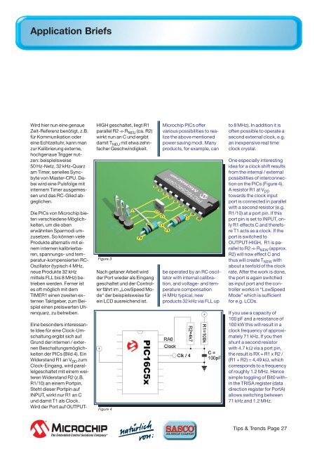
Eine besonders interessante<br />
Idee für eine Clock-Umschaltung<br />
ergibt sich auf<br />
Grund der internen / externenBeschaltungsmöglichkeiten<br />
der PICs (Bild 4). Ein<br />
Widerstand R1 an V DD zum<br />
Clock-Eingang, wird parallelgeschaltet<br />
mit einem weiteren<br />
Widerstand R2 (z.B.<br />
R1/10) an einem Portpin.<br />
Steht dieser Portpin auf<br />
INPUT, wirkt nur R1 an C<br />
und damit T1 als Clock.<br />
Wird der Port auf OUTPUT-<br />
HIGH geschaltet, liegt R1<br />
parallel R2 –> R NEU (ca. R2)<br />
wirkt nun an C und ergibt<br />
damit T NEU mit etwa zehnfacher<br />
Geschwindigkeit.<br />
Figure 3<br />
Nach getaner Arbeit wird<br />
der Port wieder als Eingang<br />
geschaltet und der Controller<br />
fährt im „LowSpeed Mode“<br />
der beispielsweise für<br />
ein LCD ausreichend ist.<br />
Figure 4<br />
Microchip PICs offer<br />
various possibilities to realize<br />
the above mentioned<br />
power saving modi. Many<br />
products, for example, can<br />
be operated by an RC oscillator<br />
with internal calibration,<br />
and voltage- and temperature<br />
compensation<br />
(4 MHz typical, new<br />
products 32 kHz via FLL up<br />
to 8 MHz). In addition it is<br />
often possible to operate a<br />
second external clock, e.g.<br />
an inexpensive real time<br />
clock crystal.<br />
One especially interesting<br />
idea for a clock shift results<br />
from the internal / external<br />
possibilities of interconnection<br />
on the PICs (Figure 4).<br />
A resistor R1 at V DD<br />
towards the clock input<br />
port is connected in parallel<br />
with a second resistor (e.g.<br />
R1/10) at a port pin. If this<br />
port pin is set to INPUT, only<br />
R1 effects C and therefore<br />
T1 acts as a clock. If the<br />
port is switched to<br />
OUTPUT-HIGH, R1 is parallel<br />
to R2 –> R NEW (approx.<br />
R2) will now effect C and<br />
thus will create T NEW with<br />
about a tenfold of the clock<br />
rate. After the work is done,<br />
the port is again switched<br />
as input port and the controller<br />
works in “LowSpeed<br />
Mode” which is sufficient<br />
for e.g. LCDs.<br />
If you use a capacity of<br />
100 pF and a resistance of<br />
100 kW this will result in a<br />
clock frequency of approximately<br />
71 kHz. If you then<br />
shunt a second resistor<br />
with 4.7 kΩ via a port pin,<br />
the result is RX = R1 x R2 /<br />
(R1 + R2) = 4,49 kΩ, which<br />
corresponds to a frequency<br />
of roughly 1.2 MHz. Hence<br />
simple toggling of Bit0 within<br />
the TRISA register (data<br />
direction register for PortA)<br />
allows switching between<br />
71 kHz and 1.2 MHz.<br />
Tips & Trends Page 27