Montage- und Reparaturanleitung SSB 16 - bei ELAFLEX
Montage- und Reparaturanleitung SSB 16 - bei ELAFLEX
Montage- und Reparaturanleitung SSB 16 - bei ELAFLEX
- Keine Tags gefunden...

Erfolgreiche ePaper selbst erstellen
Machen Sie aus Ihren PDF Publikationen ein blätterbares Flipbook mit unserer einzigartigen Google optimierten e-Paper Software.
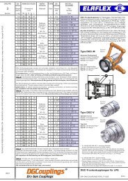
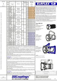
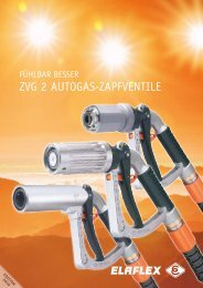
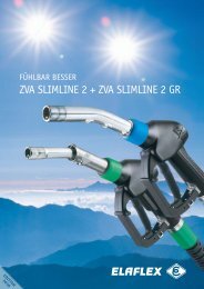
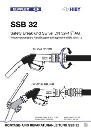
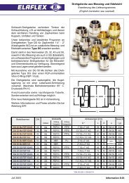
<strong>ELAFLEX</strong> SAFETY BREAKEN 13617-2WARNING REASSEMBLYAUTHORIZED PERSONNEL ONLYnozzle groove <strong>SSB</strong> <strong>16</strong> lip break sleeve BS <strong>16</strong> KS <strong>16</strong>The SAFETY SWIVEL BREAK "<strong>SSB</strong> <strong>16</strong>" is a self-sealing reusable break-away couplingdesigned to protect dispenser, hose assembly and car against damage which can occurby drive-off incidents. As a nozzle break it is directly fitted to the ZVA SLIMLINE orZVA SLIMLINE 2 nozzle. Before delivery each <strong>SSB</strong> <strong>16</strong> is tested regarding the break-off andtightness <strong>und</strong>er pressure (5.25 bar acc. to standard EN 13617-2). This is documented by thefactory date code, e.g. '1420' for 1 = Monday; 42 = calendar week 42; 0 = year 2010.When a pull between 80 kg (800 N) and 150 kg (1500N) is applied, either axially or at an angleas quite often occurs in practice, the coupling separates.warning : Before installation determine if the construction of the dispenser and the pullresistance of the hose is suitable for a pull force higher than the max. separation force,in all driveaway directions.An integral valve at the break-away part stops the flow of fuel at the hose end. Accordingto safety regulations max. 120 ml are allowed to flow out. After separation the <strong>SSB</strong> <strong>16</strong> mustbe reassembled by an authorised service engineer according to the instruction (oppositepage) and may then be used again after leakage test. The construction is such that fluid isnot sprayed out during reconnection action.installation instructionsl Switch off pump. Release pressure in hose.lRemove nozzle from hose assembly and drain hose.lRemove existing swivel from nozzle.lPush break sleeve BS <strong>16</strong> back over the hose assembly (and anti-kinking sleeve KS <strong>16</strong>).l Slightly lubricate thread; screw <strong>SSB</strong> <strong>16</strong> with assembled strainer into nozzle.l Lubricate thread and screw <strong>SSB</strong> <strong>16</strong> onto the hose assembly by using twoEW - M 36/41 wrenches, not a vice.l Prime pump and check carefully to ensure connections are tight.l Push BS <strong>16</strong> over <strong>SSB</strong> <strong>16</strong> until the lip rests in the groove.If the <strong>SSB</strong> <strong>16</strong> was factory fitted to the nozzle, the assembly on the hose is done the sameway as described above.The drawing below shows the assembled system with the correct position of the strainer.The break sleeve BS <strong>16</strong> is an integral part of the <strong>SSB</strong> <strong>16</strong> and helps protect the break-awaypart against external damage in the event of a drive-off. A range of colours is available forproduct identification to prevent misfuellings.strainerRevision12.11