ECHONews - SOCON Sonar Control Kavernenvermessung GmbH
ECHONews - SOCON Sonar Control Kavernenvermessung GmbH
ECHONews - SOCON Sonar Control Kavernenvermessung GmbH

Erfolgreiche ePaper selbst erstellen
Machen Sie aus Ihren PDF Publikationen ein blätterbares Flipbook mit unserer einzigartigen Google optimierten e-Paper Software.
The gas drying unit (GDU)<br />
When gas flows through the GDU the<br />
pressure and temperature is reduced.<br />
The pressure drop depends upon the volumetric<br />
flow and real values are used for<br />
the calibration. For a given rate the pressure<br />
drop can be interpolated by a spline.<br />
A „good“ approximation is yielded from<br />
a large number of accurate measured values<br />
and provides a „reasonable“ assessment<br />
of the pressure drop. When multiple<br />
GDU‘s are working in parallel the gas<br />
stream is split in line with the number of<br />
used GDU’s. The volumetric flow leads to<br />
a smaller pressure drop.<br />
The pressure reduction stream and<br />
heat exchanger<br />
If the combined cavern pressure compared<br />
to the transmission pipeline (national<br />
grid) pressure is very high, then<br />
the pressure is reduced to the pressure<br />
which is necessary to transfer the gas<br />
into the transmission pipeline plus pressure<br />
losses in the station piping and the<br />
meter streams. The heat exchanger has<br />
the job of raising the gas temperature to<br />
achieve a minimum temperature of 18°C<br />
downstream the pressure reduction station.<br />
Temperatures are generally calculated<br />
using the Joule-Thomson algorithm.<br />
The calculations have been taken from<br />
the worksheet G499 published by the<br />
German Technical Association for Gas<br />
and Water (DVGW) [5].<br />
Possible scenarios during injection /<br />
withdrawal<br />
Essentially four cases can be differentiated<br />
in the calculations for the above<br />
ground procedures:<br />
1. Withdrawal without compression<br />
2. Withdrawal with compression<br />
3. Injection without compression<br />
4. Injection with compression<br />
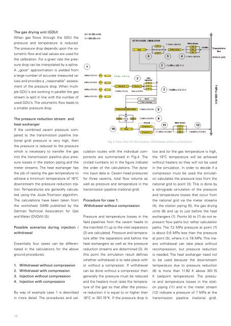
By way of example case 1 is described<br />
in more detail. The procedures and cal-<br />
10<br />
Fig.4: Flow chart for the situation: Withdrawal without compression<br />
culation routes with the individual components<br />
are summarised in Fig.4. The<br />
circled numbers (x) in the figure indicate<br />
the order of the calculations. The dynamic<br />
input data is: Cavern head pressures<br />
for three caverns, total flow volume as<br />
well as pressure and temperature in the<br />
transmission pipeline (national grid).<br />
Procedure for case 1:<br />
Withdrawal without compression<br />
Pressure and temperature losses in the<br />
field pipelines from the cavern heads to<br />
the manifold (1) up to the inlet separators<br />
(2) are calculated. Pressure and temperature<br />
after the separators and before the<br />
heat exchangers as well as the pressure<br />
reduction streams are determined (3). At<br />
this point the simulation result defines<br />
whether withdrawal is to take place with<br />
or without a compressor. If withdrawal<br />
can be done without a compressor then<br />
generally the pressure must be reduced<br />
and the heaters must raise the temperature<br />
of the gas so that after the pressure<br />
reduction it is equal to or higher than<br />
18°C or 301.15°K. If the pressure drop is<br />
low and /or the gas temperature is high,<br />
the 18°C temperature will be achieved<br />
without heaters so they will not be used<br />
in the simulation. In order to decide if a<br />
compressor must be used the simulation<br />
calculates the pressure loss from the<br />
national grid to point (3). This is done by<br />
a retrograde simulation of the pressure<br />
and temperature losses that occur from<br />
the national grid via the meter streams<br />
(4), the station piping (5), the gas drying<br />
units (6) and up to just before the heat<br />
exchangers (7). Points (4) to (7) do not represent<br />
flow paths but rather calculation<br />
paths. The 7.2 MPa pressure at point (7)<br />
is about 0.6 MPa less than the pressure<br />
at point (3), where it is 7.8 MPa. This means<br />
withdrawal can take place without<br />
recompression, but pressure reduction<br />
is needed. The heat exchanger need not<br />
to be used because the downstream<br />
temperature due to pressure reduction<br />
(8) is more than 11.92 K above 301.15<br />
K (setpoint temperature). The pressure<br />
and temperature losses in the station<br />
piping (11) and in the meter stream<br />
(12) indicate a pressure of 7 MPa at the<br />
transmission pipeline (national grid).