JB N55 Stage 1 and Stage 2 Install Guide
JB N55 Stage 1 and Stage 2 Install Guide
JB N55 Stage 1 and Stage 2 Install Guide

You also want an ePaper? Increase the reach of your titles
YUMPU automatically turns print PDFs into web optimized ePapers that Google loves.
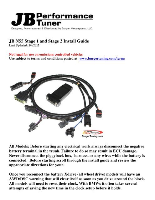
<strong>JB</strong> <strong>N55</strong> <strong>Stage</strong> 1 <strong>and</strong> <strong>Stage</strong> 2 <strong>Install</strong> <strong>Guide</strong><br />
Last Updated: 1/4/2012<br />
Not legal for use on emissions controlled vehicles<br />
Use subject to terms <strong>and</strong> conditions posted at: www.burgertuning.com/terms<br />
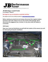
All Models: Before starting any electrical work always disconnect the negative<br />
battery terminal in the trunk. Failure to do so may result in ECU damage.<br />
Never disconnect the piggyback box, harness, or any wires while the battery is<br />
connected. Before starting scroll through the install guide <strong>and</strong> review the<br />
appropriate directions for your.<br />
Once you reconnect the battery Xdrive (all wheel drive) models will have an<br />
AWD/DSC warning that will clear itself as soon as you drive around the block.<br />
All models will need to reset their clock. With BMWs it often takes several<br />
attempts of saving the new time in the clock setup before it holds.
135 <strong>and</strong> E90 335:<br />
1) Remove the HVAC air filter <strong>and</strong> cowl. Refer to the N54 <strong>Stage</strong> 3 guide/video for detailed<br />
directions <strong>and</strong> photos.<br />
2) Remove the yellow ECU cover. This is where the <strong>Stage</strong>1 control unit will be placed at the<br />
conclusion of the harness install.<br />
3) Lay the harness along the top of the motor next to the existing harness with the <strong>Stage</strong>1 DB25<br />
connector located in the ECU box. Tuck it under the strut tower brace when routing.<br />
4) The harness consists of 4 plugs each of which intercept a particular sensor. The spacing is<br />
such that it is not possible to connect them in the wrong positions, but it may be possible to plug<br />
a connector in backwards, so take care of the orientation <strong>and</strong> ensure the tab on each connector is<br />
locking properly.<br />
5) Identify <strong>and</strong> plug in to each sensor as shown.
The first is the TMAP sensor. It can be useful to use the flat side of a USB cable to unlock the<br />
TMAP <strong>and</strong> MAP sensors. Just slide the USB in to unlock the tab <strong>and</strong> tug the plug out.<br />
Alternatively a penny or small screwdriver will also do the trick. Once unplugged insert the<br />
<strong>Stage</strong>1 TMAP plug <strong>and</strong> plug the original in to the <strong>Stage</strong>1 female plug as shown.
The MAP sensor is positioned partly under a plastic cover which can be lifted up with your<br />
h<strong>and</strong> as shown. <strong>Install</strong> is the same as the TMAP sensor.
The MAF sensor is the easiest to reach right on top of the engine. Note the orientation as shown<br />
in the photo as this connector can easily be plugged in backwards.
The boost solenoid is located on the passenger side of the engine <strong>and</strong> can be tricky to reach. It<br />
also gets very hot so either wear a glove or wait for your motor to cool down. You release the<br />
OEM connector by pushing in on the metal release clip <strong>and</strong> lifting the plug up. Similarly you<br />
push the metal release clip in when inserting the <strong>Stage</strong>1 connector. Plug the original in to the<br />
corresponding <strong>Stage</strong> 1 connector.
Finally connect the <strong>Stage</strong> 1 control box as shown <strong>and</strong> tighten the two screws h<strong>and</strong> tight with a<br />
small screwdriver. If you have opted for the optional USB cable for future software updates you<br />
can connect that to the small DB9 connector on the back of the <strong>Stage</strong> 1 at this time.<br />
Alternatively you can leave that connector unplugged if you do not have the optional USB<br />
cable.<br />
Slide the control box in to the yellow ECU area <strong>and</strong> reinstall the yellow ECU cover. Route the<br />
harness bundle between the rubber grommet <strong>and</strong> the yellow ECU cover under one of the two<br />
indented areas.<br />
For <strong>Stage</strong> 1 the additional wires bundled next to the <strong>Stage</strong>1 control box are not used <strong>and</strong><br />
should be left bundled.<br />
For <strong>Stage</strong> 2 refer to the additional directions at the bottom of this file for connecting the power,<br />
ground, <strong>and</strong> CAN communication wires.<br />
If you installed the optional USB cable you can route that between the smaller rubber grommet<br />
<strong>and</strong> the yellow ECU cover on the opposite side.<br />
Before reinstalling the cowl start the car. If you receive a CEL (check engine light, picture of a<br />
yellow engine inside the dash) double check each connection. If you’re unable to see any<br />
problems take photos of the install <strong>and</strong> email to terry@burgertuning.com for troubleshooting<br />
support.<br />
Assuming the car starts <strong>and</strong> idles without a CEL reinstall the cowl/HVAC cover <strong>and</strong> installation<br />
is complete. Both <strong>Stage</strong>1 <strong>and</strong> <strong>Stage</strong>2 come preset so no additional software changes are<br />
required. Just drive <strong>and</strong> enjoy!
RHD 135 / 335 <strong>Stage</strong> 1<br />
Directions are the same as above only instead of locating the <strong>Stage</strong>1 control box in the DME<br />
you will place it next to the passenger side brake booster as shown.
535 F10, X3, <strong>and</strong> X5 models:<br />
<strong>Install</strong>ation is the same as above with the following differences:<br />
1) You do not need to remove the cowl/HVAC assembly.<br />
2) To access the MAP sensor, connector #2, you must loosen <strong>and</strong> pull up the airbox assembly a<br />
few inches. Remove the rubber grommets holding wire bundles, loose the worm clamp, <strong>and</strong><br />
physically pull the airbox up off its rubber mounts high enough to reach the sensor below.<br />
3) The <strong>Stage</strong>1 control box will be located under a plastic cover on the passenger side as shown.
F30 Models:<br />
F30 models install similar to the F10 above, only you will connect #1/TMAP <strong>and</strong> #2/MAP<br />
connectors only. Connectors #3 & #4 are not utilized. Just tuck these out of the way during the<br />
install. Leaving them disconnected tells the control box to utilize the appropriate performance<br />
mapping for the F30. The additional wires bundled next to the <strong>Stage</strong>1 control box are not used<br />
<strong>and</strong> should be left bundled.<br />
135 / 335 <strong>Stage</strong> 2 Additional Wires:<br />
<strong>Stage</strong>2 has four additional wires which must be connected. Ground runs under the DME box<br />
grommet to the shock tower ground location as shown. Power gets pushed in along with the big<br />
red fuse in the DME box. And the two CAN communication wires attach to the CAN network<br />
as shown.<br />
Locate <strong>and</strong> remove the felt-tape holding the wire bundle together <strong>and</strong> pull out the blue <strong>and</strong> red<br />
CAN wire bundles as shown below. It will be the only bundle wrapped in black felt tape. If you<br />
can't find it, keep looking, it's easy to miss but is right in front of you. Each one will have a<br />
black cap on top of it. Pull the cap off <strong>and</strong> ensure the wire leads are clean. If needed you can<br />
clean them using a paper towel <strong>and</strong> rubbing alcohol. A clean connection here is critical to the<br />
CAN system functioning properly. wrap the <strong>Stage</strong>2 wire around the exposed leads <strong>and</strong> push the<br />
cap back over ensuring a solid connection. If your CAN wires have the white cap glued on you<br />
will need a heat gun or a hair dryer to remove it. Refer to those photos below for additional<br />
directions.
For RHD models you'll need the $30 right h<strong>and</strong> drive harness extender on our site.<br />
<strong>Install</strong>ation is the same as shown above only the DME is located on the opposite<br />
side of the engine bay.<br />
For additional <strong>Stage</strong>2 information on maps, wheel control directions,<br />
software, etc, please refer to this link:<br />
http://www.n54tech.com/forums/showthread.php?t=13189