Juice Box Stage 4 PnP - Burger Motorsports
Juice Box Stage 4 PnP - Burger Motorsports
Juice Box Stage 4 PnP - Burger Motorsports

You also want an ePaper? Increase the reach of your titles
YUMPU automatically turns print PDFs into web optimized ePapers that Google loves.
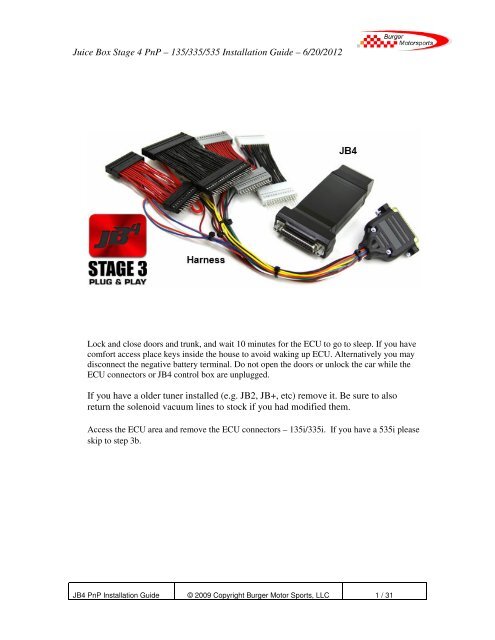
<strong>Juice</strong> <strong>Box</strong> <strong>Stage</strong> 4 <strong>PnP</strong> – 135/335/535 Installation Guide – 6/20/2012<br />
Lock and close doors and trunk, and wait 10 minutes for the ECU to go to sleep. If you have<br />
comfort access place keys inside the house to avoid waking up ECU. Alternatively you may<br />
disconnect the negative battery terminal. Do not open the doors or unlock the car while the<br />
ECU connectors or JB4 control box are unplugged.<br />
If you have a older tuner installed (e.g. JB2, JB+, etc) remove it. Be sure to also<br />
return the solenoid vacuum lines to stock if you had modified them.<br />
Access the ECU area and remove the ECU connectors – 135i/335i. If you have a 535i please<br />
skip to step 3b.<br />
JB4 <strong>PnP</strong> Installation Guide<br />
© 2009 Copyright <strong>Burger</strong> Motor Sports, LLC<br />
1 / 31
<strong>Juice</strong> <strong>Box</strong> <strong>Stage</strong> 4 <strong>PnP</strong> – 135/335/535 Installation Guide – 6/20/2012<br />
Reference Picture:<br />
JB4 <strong>PnP</strong> Installation Guide<br />
© 2009 Copyright <strong>Burger</strong> Motor Sports, LLC<br />
2 / 31
<strong>Juice</strong> <strong>Box</strong> <strong>Stage</strong> 4 <strong>PnP</strong> – 135/335/535 Installation Guide – 6/20/2012<br />
Remove the left and right plastic covers as shown with green arrows. Pull the rubber tab down,<br />
and use your fingers to snap each cover off. Place them out of the way.<br />
Pulling cover away:<br />
JB4 <strong>PnP</strong> Installation Guide<br />
© 2009 Copyright <strong>Burger</strong> Motor Sports, LLC<br />
3 / 31
<strong>Juice</strong> <strong>Box</strong> <strong>Stage</strong> 4 <strong>PnP</strong> – 135/335/535 Installation Guide – 6/20/2012<br />
Remove the left and right connectors/sensors as shown in purple. The passenger side<br />
sensor removes by pushing in a small clip and rotating, while the optional driver side will<br />
lift off it present. Pull the tabs holding the wires out by grasping the tabs and pulling<br />
towards you. The sensors will stay connected to the wires, just lay the sensors and wires<br />
towards the front of the engine out of the way.<br />
Optional driver side sensor:<br />
Passenger side sensor:<br />
JB4 <strong>PnP</strong> Installation Guide<br />
© 2009 Copyright <strong>Burger</strong> Motor Sports, LLC<br />
4 / 31
<strong>Juice</strong> <strong>Box</strong> <strong>Stage</strong> 4 <strong>PnP</strong> – 135/335/535 Installation Guide – 6/20/2012<br />
Remove the six 8mm bolts holding down the HVAC air filter (shown in orange) and pull off the<br />
filter. Place it on the ground out of the way.<br />
Remove the two 8mm machine bolts shown in blue. These hold down the plastic cowl that we<br />
will be removing. There are two rubber tabs on the left and right of the cowl that must be pulled<br />
out, as well as a wash fluid line on the left side.<br />
Using a flat head screwdriver, push down the clips and pull forward the plastic rail holding the<br />
battery cable as shown. This will remain in the car when the cowl is removed.<br />
JB4 <strong>PnP</strong> Installation Guide<br />
© 2009 Copyright <strong>Burger</strong> Motor Sports, LLC<br />
5 / 31
<strong>Juice</strong> <strong>Box</strong> <strong>Stage</strong> 4 <strong>PnP</strong> – 135/335/535 Installation Guide – 6/20/2012<br />
Next use the flat head screwdriver to release the cable bundle running right behind the power strip<br />
you just removed. Pull the cable forward while lifting up the cowl to release it. The cowl should<br />
now lift out of the engine bay. Place it on the ground out of the way.<br />
Once the cowl is removed your engine bay should look like this:<br />
JB4 <strong>PnP</strong> Installation Guide<br />
© 2009 Copyright <strong>Burger</strong> Motor Sports, LLC<br />
6 / 31
<strong>Juice</strong> <strong>Box</strong> <strong>Stage</strong> 4 <strong>PnP</strong> – 135/335/535 Installation Guide – 6/20/2012<br />
Finally remove the left yellow plastic cover to expose the ECU. It is held down by two sliding<br />
clips on the sides, and small plastic clips on the front and back.<br />
JB4 <strong>PnP</strong> Installation Guide<br />
© 2009 Copyright <strong>Burger</strong> Motor Sports, LLC<br />
7 / 31
<strong>Juice</strong> <strong>Box</strong> <strong>Stage</strong> 4 <strong>PnP</strong> – 135/335/535 Installation Guide – 6/20/2012<br />
3B. 535i ECU access. If you have a 135/335 you have already completed this step.<br />
Skip to step 4.<br />
535i engine bay reference picture:<br />
JB4 <strong>PnP</strong> Installation Guide<br />
© 2009 Copyright <strong>Burger</strong> Motor Sports, LLC<br />
8 / 31
<strong>Juice</strong> <strong>Box</strong> <strong>Stage</strong> 4 <strong>PnP</strong> – 135/335/535 Installation Guide – 6/20/2012<br />
Disconnect the two sensors located by the hvac filter as shown.<br />
Use a 12mm socket unlock the plastic bolt by gently turning it 1/4 turn, and then release the metal<br />
latch holding it down.<br />
JB4 <strong>PnP</strong> Installation Guide<br />
© 2009 Copyright <strong>Burger</strong> Motor Sports, LLC<br />
9 / 31
<strong>Juice</strong> <strong>Box</strong> <strong>Stage</strong> 4 <strong>PnP</strong> – 135/335/535 Installation Guide – 6/20/2012<br />
The filter should lift up and out as shown.<br />
Pull off the weather stripping by pulling straight up and away until it has cleared the left tray, or<br />
about half way across the engine.<br />
JB4 <strong>PnP</strong> Installation Guide<br />
© 2009 Copyright <strong>Burger</strong> Motor Sports, LLC<br />
10 / 31
<strong>Juice</strong> <strong>Box</strong> <strong>Stage</strong> 4 <strong>PnP</strong> – 135/335/535 Installation Guide – 6/20/2012<br />
Remove the slider as shown by lifting the clip and sliding towards the driver side.<br />
Release the left side tray by rotating the 4 plastic retaining bolts 1/4 turn.<br />
JB4 <strong>PnP</strong> Installation Guide<br />
© 2009 Copyright <strong>Burger</strong> Motor Sports, LLC<br />
11 / 31
<strong>Juice</strong> <strong>Box</strong> <strong>Stage</strong> 4 <strong>PnP</strong> – 135/335/535 Installation Guide – 6/20/2012<br />
Lift away the rubber guard as shown.<br />
Remove the t25 torx screw holding the tray to the shock tower.<br />
JB4 <strong>PnP</strong> Installation Guide<br />
© 2009 Copyright <strong>Burger</strong> Motor Sports, LLC<br />
12 / 31
<strong>Juice</strong> <strong>Box</strong> <strong>Stage</strong> 4 <strong>PnP</strong> – 135/335/535 Installation Guide – 6/20/2012<br />
Finally slide the tray towards the fender, up, and out.<br />
Use an allen wrench to remove the 5 screws holding down the ECU cover.<br />
JB4 <strong>PnP</strong> Installation Guide<br />
© 2009 Copyright <strong>Burger</strong> Motor Sports, LLC<br />
13 / 31
<strong>Juice</strong> <strong>Box</strong> <strong>Stage</strong> 4 <strong>PnP</strong> – 135/335/535 Installation Guide – 6/20/2012<br />
Release the sliding lock in the back of the box, and remove the lid.<br />
Finally, ECU access!<br />
JB4 <strong>PnP</strong> Installation Guide<br />
© 2009 Copyright <strong>Burger</strong> Motor Sports, LLC<br />
14 / 31
<strong>Juice</strong> <strong>Box</strong> <strong>Stage</strong> 4 <strong>PnP</strong> – 135/335/535 Installation Guide – 6/20/2012<br />
1) Remove both the large and small ECU connectors and slide out all 4 subconnectors.<br />
Large black and small white are from the larger left connector, small grey and small<br />
black are from the smaller right connector. The slider must be removed from the small<br />
ECU connector to get the subconnectors out. It is generally easier to pull the large<br />
harness grommets off of the ends of the yellow ECU box to make room to work. It may<br />
take some force to pull the sliders out.<br />
Removing the slider from the smaller driver side subconnector.<br />
JB4 <strong>PnP</strong> Installation Guide<br />
© 2009 Copyright <strong>Burger</strong> Motor Sports, LLC<br />
15 / 31
<strong>Juice</strong> <strong>Box</strong> <strong>Stage</strong> 4 <strong>PnP</strong> – 135/335/535 Installation Guide – 6/20/2012<br />
ECU with connectors removed. Refer to step 3 for details if needed.<br />
Removing large black subconnector. Refer to step 3 for details if needed.<br />
JB4 <strong>PnP</strong> Installation Guide<br />
© 2009 Copyright <strong>Burger</strong> Motor Sports, LLC<br />
16 / 31
<strong>Juice</strong> <strong>Box</strong> <strong>Stage</strong> 4 <strong>PnP</strong> – 135/335/535 Installation Guide – 6/20/2012<br />
All four subconnectors removed.<br />
2) The JB4 harness is organized in to red and black wires. The black wires go on the<br />
left larger ECU connector, the red wires go on the smaller right ECU connector.<br />
They will only slide in one way. Angle the wires as you insert them so they fully<br />
seat. The connectors should lock in place like the factory subconnectors. Newer<br />
JB4 harnesses will have a white connector with black wires to match the factory<br />
connector color. Older harnesses have a black connector with black wires. They<br />
are used interchangeably in the following photos so please pay close attention and<br />
verify you have the connecters with black wires installed on the larger of the two<br />
sub connectors and connectors with red wires on the smaller of the two.<br />
JB4 <strong>PnP</strong> Installation Guide<br />
© 2009 Copyright <strong>Burger</strong> Motor Sports, LLC<br />
17 / 31
<strong>Juice</strong> <strong>Box</strong> <strong>Stage</strong> 4 <strong>PnP</strong> – 135/335/535 Installation Guide – 6/20/2012<br />
JB4 <strong>PnP</strong> Installation Guide<br />
.<br />
3) Reinstall the small slider and reinstall the ECU connectors to the ECU. The larger<br />
connector can be a pain to get in, move the slider in and out as you wiggle the connector.<br />
As you push the slider in the connector should be sucked down when properly aligned.<br />
© 2009 Copyright <strong>Burger</strong> Motor Sports, LLC<br />
18 / 31
<strong>Juice</strong> <strong>Box</strong> <strong>Stage</strong> 4 <strong>PnP</strong> – 135/335/535 Installation Guide – 6/20/2012<br />
Do not reinstall the connectors without the slider.<br />
4) Plug in the original black 44 pin subconnector to the large black subconnector on the JB4<br />
harness. You can plug the connector in backwards so take care to ensure the horizontal<br />
slots / empty boxes at the front of each connector are to the right.<br />
JB4 <strong>PnP</strong> Installation Guide<br />
© 2009 Copyright <strong>Burger</strong> Motor Sports, LLC<br />
19 / 31
<strong>Juice</strong> <strong>Box</strong> <strong>Stage</strong> 4 <strong>PnP</strong> – 135/335/535 Installation Guide – 6/20/2012<br />
5) Plug in the factory short white subconnector to the small white or black<br />
subconnector (with black wires towards passenger side) on the JB4 harness.<br />
6)<br />
JB4 <strong>PnP</strong> Installation Guide<br />
© 2009 Copyright <strong>Burger</strong> Motor Sports, LLC<br />
20 / 31
<strong>Juice</strong> <strong>Box</strong> <strong>Stage</strong> 4 <strong>PnP</strong> – 135/335/535 Installation Guide – 6/20/2012<br />
7) Plug in the factory short black subconnector to the small black subconnector (with red<br />
wires) on the JB4 harness. Verify boxes line up.<br />
8) Plug in the factory short grey subconnector to the small grey subconnector on the JB4<br />
harness. Verify boxes line up.<br />
JB4 <strong>PnP</strong> Installation Guide<br />
© 2009 Copyright <strong>Burger</strong> Motor Sports, LLC<br />
21 / 31
<strong>Juice</strong> <strong>Box</strong> <strong>Stage</strong> 4 <strong>PnP</strong> – 135/335/535 Installation Guide – 6/20/2012<br />
12) Install the JB4 power wire as shown in these photos:<br />
JB4 <strong>PnP</strong> Installation Guide<br />
© 2009 Copyright <strong>Burger</strong> Motor Sports, LLC<br />
22 / 31
<strong>Juice</strong> <strong>Box</strong> <strong>Stage</strong> 4 <strong>PnP</strong> – 135/335/535 Installation Guide – 6/20/2012<br />
JB4 <strong>PnP</strong> Installation Guide<br />
© 2009 Copyright <strong>Burger</strong> Motor Sports, LLC<br />
23 / 31
<strong>Juice</strong> <strong>Box</strong> <strong>Stage</strong> 4 <strong>PnP</strong> – 135/335/535 Installation Guide – 6/20/2012<br />
JB4 <strong>PnP</strong> Installation Guide<br />
© 2009 Copyright <strong>Burger</strong> Motor Sports, LLC<br />
24 / 31
<strong>Juice</strong> <strong>Box</strong> <strong>Stage</strong> 4 <strong>PnP</strong> – 135/335/535 Installation Guide – 6/20/2012<br />
JB4 <strong>PnP</strong> Installation Guide<br />
© 2009 Copyright <strong>Burger</strong> Motor Sports, LLC<br />
25 / 31
<strong>Juice</strong> <strong>Box</strong> <strong>Stage</strong> 4 <strong>PnP</strong> – 135/335/535 Installation Guide – 6/20/2012<br />
JB4 <strong>PnP</strong> Installation Guide<br />
© 2009 Copyright <strong>Burger</strong> Motor Sports, LLC<br />
26 / 31
<strong>Juice</strong> <strong>Box</strong> <strong>Stage</strong> 4 <strong>PnP</strong> – 135/335/535 Installation Guide – 6/20/2012<br />
JB4 <strong>PnP</strong> Installation Guide<br />
© 2009 Copyright <strong>Burger</strong> Motor Sports, LLC<br />
27 / 31
<strong>Juice</strong> <strong>Box</strong> <strong>Stage</strong> 4 <strong>PnP</strong> – 135/335/535 Installation Guide – 6/20/2012<br />
Ensure the male/female power wire connection is secure as you push the green connector<br />
down. If this connection comes loose while driving the motor will stall out and not restart.<br />
13) Insert the JB4 AMP connector in to the JB4 box, and tighten screws. Not connecting<br />
the actual JB4 computer to the harness is the most common installation mistake made. Slide<br />
the JB4 box in to the left tray perpendicular to the ECU as shown above, or any available open<br />
ECU slot.<br />
14) If removed reinstall the harness grommets and fold over the JB4 harness and OEM<br />
subconnectors to make room for the yellow ECU cover. In some cars with certain options the<br />
long black subconnector will only fold over towards the firewall, in most cars it can be folded<br />
towards the front of the car. The other three smaller subconnectors fold towards the front of the<br />
car. Once folded gently push all of the connectors down with the palm of your hand so they stay<br />
relatively flat like the above photo.<br />
JB4 <strong>PnP</strong> Installation Guide<br />
© 2009 Copyright <strong>Burger</strong> Motor Sports, LLC<br />
28 / 31
<strong>Juice</strong> <strong>Box</strong> <strong>Stage</strong> 4 <strong>PnP</strong> – 135/335/535 Installation Guide – 6/20/2012<br />
15) Double check to ensure all subconnectors are fully plugged in, and reinstall yellow ECU<br />
cover.<br />
16) If you disconnected the battery reconnect the negative battery terminal. Upon first starting the<br />
car you will have a clock warning (triangle with ! in the middle of it). All wheel drive (Xi)<br />
models may also have a DTS/DTC warning message, which will turn itself off after a short drive.<br />
It is also not uncommon to have to set the clock 2 or 3 times before it saves.<br />
17) Before reinstalling cowl and covers start the car. If it fails to start, takes a long time to start,<br />
shows a picture of a half yellow engine in the dash (CEL), an orange service engine soon light<br />
(SES), or runs extremely rough, please refer to the troubleshooting guide below. Please note it is<br />
normal on an unmodified car for the SES light to illuminate with the ignition on before starting<br />
the motor. Only an SES light on with the motor running would be abnormal.<br />
18) Optional BMS USB cable. If you elected to purchase the BMS USB cable for free firmware<br />
updates, new features, etc, as we post them to N54Tech.com, connect it to the bottom of the JB4<br />
control box. For cable routing you have two options. Option 1 is to route it over the rubber<br />
grommet under the DME cover and leave it there for quick access. You'll just have to lift up the<br />
one snap on black panel and can then route it in the window or door jamb to your laptop. Option<br />
2 is to route it in to the glove box. There is a DIY here:<br />
http://www.n54tech.com/forums/showthread.php?t=6557<br />
Assuming all is well; reinstall the ECU cover, factory cowl, and related parts.<br />
Congratulations, installation is complete! It will take a few driving cycles for the ECU to adapt to<br />
the new tune, so drive as you normally would and the car will gradually pickup power as time<br />
passes. Keep in mind the JB4 includes cold/hot oil temperature protection so when oil<br />
temperatures are below 160F degrees or over 270F degrees you will experience stock like<br />
performance.<br />
By default map 1 is selected which is recommended for unmodified cars. For the full map and<br />
steering wheel control guide as well as the latest firmware and updates visit:<br />
http://www.n54tech.com/forums/showthread.php?t=10605<br />
If you have a 135i be sure to switch the steering wheel controls to 135i mode (menu 5 option 1)<br />
using guide in above link.<br />
Remember to always use 91 octane (USA RM/2 standard) or higher grade fuel. The higher the<br />
octane, the more power you will make. 93 octane will make more power than 91 octane, and 100<br />
octane or a mix will make more power than straight 93 octane. Never use leaded or low lead fuel<br />
as it will damage your o2 sensors and/or catalytic converters. For extended load use (e.g. road<br />
race course) mixing in higher octane fuel is suggested.<br />
JB4 <strong>PnP</strong> Installation Guide<br />
© 2009 Copyright <strong>Burger</strong> Motor Sports, LLC<br />
29 / 31
<strong>Juice</strong> <strong>Box</strong> <strong>Stage</strong> 4 <strong>PnP</strong> – 135/335/535 Installation Guide – 6/20/2012<br />
*** DISCLAIMER ***<br />
Because of its intended usage, <strong>Burger</strong> <strong>Motorsports</strong>, LLC & Terry <strong>Burger</strong> make no warranties<br />
whatsoever, expressed or implied, written or oral, to purchasers of <strong>Burger</strong> <strong>Motorsports</strong> products<br />
regarding performance, safety, fit, merchantability, length of service, or for any other criteria.<br />
Purchasers are responsible for selection of proper goods and must rely on their own skills and<br />
judgment that such goods are suitable for purchasers’ application.<br />
Use subject to terms and conditions posted at http://www.burgertuning.com/terms<br />
How to read engine codes / reduced power mode / service engine soon light:<br />
Any time you get check engine light (yellow half engine or reduced power indicator) or<br />
service engine soon light (orange SES) the first step is to read the codes. With a JB4<br />
installed there are two methods. The easiest method for beginners is to connect the laptop<br />
interface and use the "read codes" button under settings. This will give a full listing along<br />
with descriptions. Alternatively for more advanced users or if a laptop isn't available you<br />
may use the in dash reading on menu 1 option 1. Directions for that method are here:<br />
http://www.n54tech.com/forums/showpost.php?p=170898&postcount=1<br />
If a JB4 is not installed you can also use a BT or CT tool to do the scan. Once you have<br />
the exact code details email those in for advice.<br />
Troubleshooting Guide<br />
Troubleshooting is broken in to two distinct groups. The first are issues that come up during<br />
installation, like failure to start, yellow engine light (CEL) upon first start, etc. The second are<br />
issues that arise after the tuner has been installed and working properly for some time.<br />
This guide deals only with installation related issues. But should you ever experience a yellow<br />
engine light (CEL) or service engine soon code (SES), you should email BMS directly at<br />
terry@burgertuning.com for technical advice. We have seen it all and can quickly help you<br />
determine whether or not the issue is related to the JB4 and what to do next. We encourage<br />
customers NOT to make pleas for help on internet forums as more often than not they receive<br />
incorrect or bad information. By purchasing a tuner from BMS you have paid for support, so feel<br />
free to use it!<br />
JB4 <strong>PnP</strong> Installation Guide<br />
© 2009 Copyright <strong>Burger</strong> Motor Sports, LLC<br />
30 / 31
<strong>Juice</strong> <strong>Box</strong> <strong>Stage</strong> 4 <strong>PnP</strong> – 135/335/535 Installation Guide – 6/20/2012<br />
Common installation problems:<br />
Engine cranks and cranks but will not start or takes a long time to start:<br />
Cause 1) One or both ECU connectors are not fully seated. They can be tricky to get in but when<br />
done properly the connector will seat itself as you are pushing the slider in. Remove connectors<br />
and try again until you are positive they are fully seated.<br />
Cause 2) One of the subconnectors is installed backwards, or is not lined up properly. Unplug all<br />
subconnectors and carefully reinsert using install guide photos as reference.<br />
Cause 3) You forgot to plug the JB4 box in to the harness.<br />
Engine starts but has a big yellow check engine light showing (CEL):<br />
Cause 1) One of the subconnectors is installed backwards, or is not lined up properly. Unplug all<br />
connectors and try again.<br />
Cause 2) JB4 control box not plugged in.<br />
Cause 3) Physical wire harness issue. You can use this guide to verify your JB4 harness and the<br />
<strong>PnP</strong> connectors are mated properly. Also verify each harness wire runs straight up and down from<br />
male to female and that no two wires were switched during final assembly.<br />
http://www.burgertuning.com/instructions/JB4_pnp_upgrade.pdf<br />
Cause 4) Incompatibility issue with O2 simulator. This only effects customers with<br />
aftermarket O2 simulators/downpipes. Contact us for further instruction.<br />
Engine starts with no lights, but upon first drive a big yellow engine light (CEL) appears:<br />
Cause 1) Normal ECU adaptation. It takes the ECU a few cycles to fully adapt to the JB4, and in<br />
rare cases this can result in a CEL. Especially if pushing the car hard after the tuner is first<br />
installed. Restart the car (the code will disappear) and continue driving. If the code does not<br />
reappear then no further action is needed.<br />
Cause 2) Map incompatibility. Although the JB4 is designed to work for all vehicles, some ECU<br />
versions, fuels, and ambient conditions require special mapping. Contact us for further<br />
instruction.<br />
Engine starts but an orange "Service Engine Soon" (SES) light appears:<br />
Cause 1) During the installation process you had some issue that you have since<br />
corrected, but the SES light is still on. The JB4 includes code reading/deleting ability<br />
detailed in the command center document linked above. Refer to this document on how<br />
to read and delete the SES code.<br />
JB4 <strong>PnP</strong> Installation Guide<br />
© 2009 Copyright <strong>Burger</strong> Motor Sports, LLC<br />
31 / 31