JB N20 Stage 1 Install Guide
JB N20 Stage 1 Install Guide
JB N20 Stage 1 Install Guide

Create successful ePaper yourself
Turn your PDF publications into a flip-book with our unique Google optimized e-Paper software.
<strong>JB</strong> <strong>N20</strong> <strong>Stage</strong> 1 <strong>Install</strong> <strong>Guide</strong><br />
Last Updated: 12/6/2012<br />
Not legal for use on emissions controlled vehicles<br />
Use subject to terms and conditions posted at: www.burgertuning.com/terms<br />
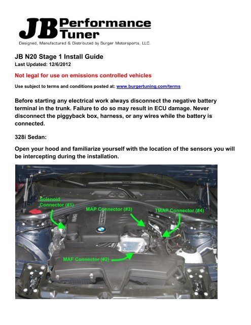
Before starting any electrical work always disconnect the negative battery<br />
terminal in the trunk. Failure to do so may result in ECU damage. Never<br />
disconnect the piggyback box, harness, or any wires while the battery is<br />
connected.<br />
328i Sedan:<br />
Open your hood and familiarize yourself with the location of the sensors you will<br />
be intercepting during the installation.
Starting near the oil cap, you will be locating the first connector for the solenoid connection. Firmly<br />
pull up on the engine cover to release it from its retainers.
Once the cover is loose you will be able to hold it up to access the solenoid connector (#1) aft of the oil<br />
cap as shown below (green arrow). If this connector is not present on your vehicle, leave this<br />
connector disconnected on the <strong>JB</strong> <strong>N20</strong> <strong>Stage</strong> 1 harness. It will remain unused.<br />
Below is a photo of the connector with the engine cover removed for illustrative purposes.
Push down on the metal retaining clip as shown and slide the connector back. Do not pull directly on<br />
the wires, make sure to pull on the connector.<br />
Lay the <strong>JB</strong> <strong>N20</strong> <strong>Stage</strong> 1 harness over the engine and locate the connector pair with blue wires. Plug<br />
the female connector on the <strong>JB</strong> <strong>N20</strong> <strong>Stage</strong> 1 harness over the factory connection as shown, making<br />
sure that the retaining clip clicks into place. Then, plug the factory harness connection you removed in<br />
the last step onto the male connector on the <strong>JB</strong> <strong>N20</strong> <strong>Stage</strong> 1 harness, making sure that the retaining<br />
clip clicks into place.
Now route the wire harness over the back of the engine cover area as shown below.<br />
Next, locate the MAF connector plug (#2) near the factory airbox at the front of the engine.
Using your fingers, push lightly on the release clip while pulling on the connector to release it. Do not<br />
pull directly on the wires.<br />
Once released, locate the connector pair with purple wires on the <strong>JB</strong> <strong>N20</strong> <strong>Stage</strong> 1 harness. Plug the<br />
small connector into the MAF sensor, with the grey retaining clip in the orientation as shown.
Now connect the large connector on the <strong>JB</strong> <strong>N20</strong> <strong>Stage</strong> 1 harness to the factory MAF connector you<br />
removed from the MAF sensor in the last step. Be sure to connect using the orientation shown.<br />
Locate the MAP Connector (#3) near the throttle body (green arrow).<br />
Using light pressure with your fingers, press on the release clip while pulling back on the connector as<br />
shown. Do not pull directly on the wires.
Once removed, locate the connector pair with brown wires on the <strong>JB</strong> <strong>N20</strong> <strong>Stage</strong> 1 harness and plug the<br />
small connector into the MAP sensor as shown. Connect the large connector from the <strong>JB</strong> <strong>N20</strong> <strong>Stage</strong> 1<br />
harness to the factory harness connector as shown below. Please note the orientation of each plug.<br />
Now locate the TMAP connector (#4) near the MAP connector and throttle body from the last step.
Push lightly on the release clip to release the connector from the sensor. Do not pull directly on the<br />
wires. Be careful to ensure that, once released, the factory connector does not fall backwards. Hold<br />
onto the connector until you have connected it to the last, multi-colored wire connector pair of the <strong>JB</strong><br />
<strong>N20</strong> <strong>Stage</strong> 1 Harness as shown. Please note the orientation of the clips in this picture. Connectors #3<br />
and #4 are both shown in this photo.<br />
Now locate the plastic cover over the brake booster as shown. Note the small ring near the side of the<br />
vehicle.
Pull up on the ring and pull the plastic cover forward to remove.<br />
Now locate the overlapping weather seal shown.
Pull the weather seal forward as shown.
Now run the <strong>JB</strong> <strong>N20</strong> <strong>Stage</strong> 1 wire harness between the split in the weather seal and replace the weather<br />
seal as shown. The portion of the wire harness with the AMP cover on the connector should now be<br />
near the brake booster.<br />
Find the <strong>JB</strong> <strong>N20</strong> <strong>Stage</strong> 1 control box and connect to the <strong>JB</strong> <strong>N20</strong> <strong>Stage</strong> 1 wire harness as shown, using a<br />
small screwdriver to secure the small screws as shown. If you have opted for the optional USB cable<br />
for future software updates you can connect that to the small connector at the opposite side of the<br />
control box at this time.
Route the <strong>JB</strong> <strong>N20</strong> <strong>Stage</strong> 1 harness and control box to a location that allows you to replace the cover.<br />
Now replace the plastic cover over the brake booster area as shown. Note the position of the <strong>JB</strong> <strong>N20</strong><br />
<strong>Stage</strong> 1 harness near the weather seal.<br />
Finally, press firmly on each side of the engine cover until it snaps into place.
Before closing the hood, reconnect your negative battery cable and start the car. If you receive a CEL<br />
(check engine light, picture of a yellow engine on the instrument display), double check each<br />
connection and the orientation of the connectors. If you’re unable to see any problems, please take<br />
photos of the install, including each connector and email to terry@burgertuning.com for<br />
troubleshooting support.<br />
Assuming the car starts and idles without a CEL, you can close the hood and trunk and your<br />
installation is complete. The <strong>JB</strong> <strong>N20</strong> <strong>Stage</strong> 1 unit is preset so no additional software changes are<br />
required. Just drive and enjoy!