BMS N54 / N55 Oil Catch Can - BurgerTuning.com
BMS N54 / N55 Oil Catch Can - BurgerTuning.com
BMS N54 / N55 Oil Catch Can - BurgerTuning.com

You also want an ePaper? Increase the reach of your titles
YUMPU automatically turns print PDFs into web optimized ePapers that Google loves.
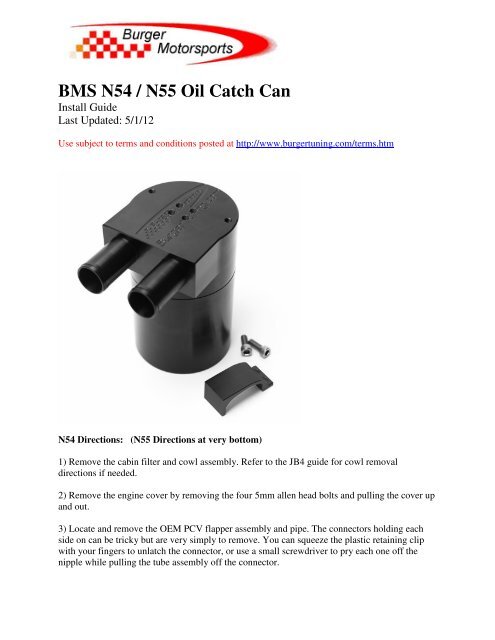
<strong>BMS</strong> <strong>N54</strong> / <strong>N55</strong> <strong>Oil</strong> <strong>Catch</strong> <strong>Can</strong><br />
Install Guide<br />
Last Updated: 5/1/12<br />
Use subject to terms and conditions posted at http://www.burgertuning.<strong>com</strong>/terms.htm<br />
<strong>N54</strong> Directions: (<strong>N55</strong> Directions at very bottom)<br />
1) Remove the cabin filter and cowl assembly. Refer to the JB4 guide for cowl removal<br />
directions if needed.<br />
2) Remove the engine cover by removing the four 5mm allen head bolts and pulling the cover up<br />
and out.<br />
3) Locate and remove the OEM PCV flapper assembly and pipe. The connectors holding each<br />
side on can be tricky but are very simply to remove. You can squeeze the plastic retaining clip<br />
with your fingers to unlatch the connector, or use a small screwdriver to pry each one off the<br />
nipple while pulling the tube assembly off the connector.
4) Once removed you will separate the flapper/connector assembly from the plastic tube. The<br />
tube is pressed on but easy to remove by hand. We strongly suggest using a heat gun or hair<br />
dryer to heat the plastic tube up and then simply pulling it off. Later, when it <strong>com</strong>es time to go<br />
back to stock, you will push the tube back on.<br />
5) Once removed cut a 16-17" piece of 3/4 hosing and press it over the flapper/connector<br />
assembly as shown. In addition cut a 6-7" piece of 3/4" hose and push it over the UBEND<br />
connection as shown. *** NOTE *** some kits are shipped with a molded 1 piece UBEND hose<br />
that dose not require any extra hose. No clamps are required on these hoses. You should now<br />
have everything shown here.
6) Push the UBEND over the OEM nipple as shown. The fit will be snug but ensure it's fully<br />
seated. No clamp is required.
7) Reinstall the flapper valve / hose assembly by clicking it in place.
8) Remove the rear diverter valve line by twisting the gray lock and pulling the tube out so it<br />
moves around freely. Only one end needs to be removed. When <strong>com</strong>plete your engine bay<br />
should look like this with two hoses ready to connect to the oil catch can.
9) Finally insert the hoses on to the <strong>BMS</strong> OCC. The UBEND hose should connect to the<br />
connection furthest away from the firewall as shown. If you find the hoses are too long at this<br />
point you can remove and trim them. No clamps are required.
10) Holding the DV line out of the way swing the OCC under the strut brace and attach using the<br />
included allen screws and bracket. Only one screw is required to hold the OCC up but both can<br />
be installed .<br />
11) When it <strong>com</strong>es times to empty the OCC every 3-6 months you will remove the cowl, the<br />
allen screw(s) holding the bracket to the strut brace, pull put the DV line, and swing the can<br />
forward so you can unscrew the can from the base. You do not need to remove the lines or<br />
engine cover to empty.<br />
12) Push the UBEND tube back as far as you can under the cowl to allow ample room to reinstall<br />
the engine cover.
13) Reinstall the engine cover. It will slightly touch the rear UBEND hose and may require a bit<br />
of force to push it back in to place and align the four 5mm allen bolts. If you find it difficult to<br />
reinstall one or both of the rear allen bolts they can be left out. Spend a little extra time here to<br />
ensure you do not "fold over" the UBEND blocking flow when reinstalling the engine cover.
13b) If the car is out of warranty and/or you don't mind trimming the engine cover to make life a<br />
little easier for yourself along with a cleaner install, you can also trim the plastic cover as shown.<br />
Use a hacksaw, cutoff wheel, or similar.
14) Once the engine cover is installed you can reinstall the cowl and cabin filter. Installation is<br />
<strong>com</strong>plete!
<strong>N55</strong> Install Directions:<br />
With <strong>N55</strong> models the OCC mounts in the front of the engine next to the coolant overflow tank as<br />
shown.<br />
1) Remove the "Twin Power" engine cover exposing the valve cover as shown above<br />
2) Unscrew the two torx screws holding the PCV assembly to the intake pipe in position C.<br />
3) Unplug the heater element wire shown in position D.<br />
4) Unlatch the PCV assembly from position A above by using a screwdriver to push back each of<br />
the 4 clips while tugging it out. It can be a bit tricky to get it off so just keep at it. Once removed<br />
store the oem pipe/valve in a safe place as it won't be used.<br />
5) Insert the <strong>BMS</strong> nipple in position C and tighten the OEM torx screws snug.<br />
6) Remove the 10mm screw in position B and slide the OCC bracket under as shown. Install the<br />
two hex screws holding the OCC to the bracket.<br />
7) Slide the 1" tube over the crank case vent A and loosely tighten the clamps.<br />
8) Cut the 3/4" hose to length and install as shown above. Note no clamps are used on the 3/4"<br />
hoses.<br />
9) Position the hoses as above and tighten the hose clamps.<br />
10) Route the unused electrical connector D over the air conditioning line as shown. It will<br />
remain unused. The OCC itself serves the same purpose of isolating water condensation from air<br />
intake path in cold weather thus this heating element is no longer required with the OCC in<br />
place.<br />
11) Reinstall the 'Twin Power" engine cover. Note it should slightly touch the OCC inlet hose.