Snap-Fit Joints for Plastics - A Design Guide - MIT
Snap-Fit Joints for Plastics - A Design Guide - MIT
Snap-Fit Joints for Plastics - A Design Guide - MIT

You also want an ePaper? Increase the reach of your titles
YUMPU automatically turns print PDFs into web optimized ePapers that Google loves.
Deflection <strong>for</strong>ce<br />
Using the equations given in Table 1, the permissible<br />
deflection y can be determined easily<br />
even <strong>for</strong> cross sections of complex shapes.<br />
The procedure is explained with the aid of an<br />
example which follows.<br />
A particularly favorable <strong>for</strong>m of snap-fitting<br />
arm is design 2 in Table 1, with the thickness<br />
of the arm decreasing linearly to half its initial<br />
value. This version increases the permissible<br />
deflection by more than 60% compared to a<br />
snap-fitting arm of constant cross section<br />
(design 1).<br />
Complex designs such as that shown in Fig. 15<br />
may be used in applications to increase the<br />
effec-tive length. Polymers Division <strong>Design</strong><br />
Engineering Services would be pleased to<br />
assist you in a curved beam analysis if you<br />
choose this type of design.<br />
The deflection <strong>for</strong>ce P required to bend the<br />
finger can be calculated by use of the equations<br />
in the bottom row of Table 1 <strong>for</strong> cross<br />
sections of various shapes.<br />
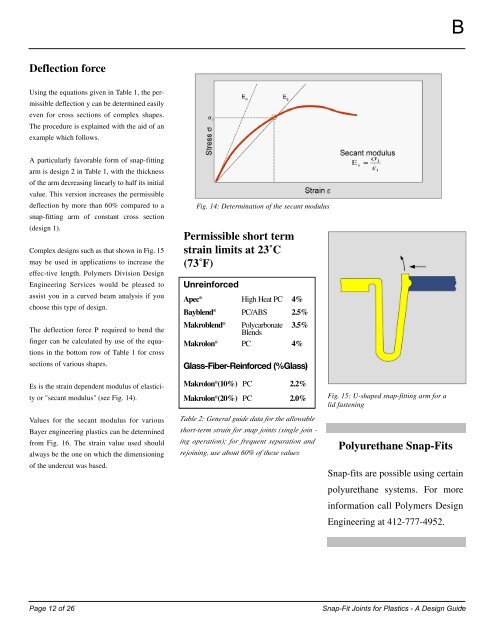
Es is the strain dependent modulus of elasticity<br />
or "secant modulus" (see Fig. 14).<br />
Values <strong>for</strong> the secant modulus <strong>for</strong> various<br />
Bayer engineering plastics can be determined<br />
from Fig. 16. The strain value used should<br />
always be the one on which the dimensioning<br />
of the undercut was based.<br />
Fig. 14: Determination of the secant modulus<br />
Permissible short term<br />
strain limits at 23˚C<br />
(73˚F)<br />
Unrein<strong>for</strong>ced<br />
Ap e c ® High Heat PC 4 %<br />
B ay bl e n d ® PC/ABS 2 . 5 %<br />
M a k ro bl e n d ® P o l y c a r b o n a t e<br />
B l e n d s<br />
3 . 5 %<br />
M a k ro l o n ® P C 4 %<br />
G l a s s - F i b e r- R e i n f o rced (%Glass)<br />
M a k ro l o n ® (10%) P C 2 . 2 %<br />
M a k ro l o n ® (20%) P C 2 . 0 %<br />
Table 2: General guide data <strong>for</strong> the allowable<br />
short-term strain <strong>for</strong> snap joints (single join -<br />
ing operation); <strong>for</strong> frequent separation and<br />
rejoining, use about 60% of these values<br />
Fig. 15: U-shaped snap-fitting arm <strong>for</strong> a<br />
lid fastening<br />
Polyurethane <strong>Snap</strong>-<strong>Fit</strong>s<br />
B<br />
<strong>Snap</strong>-fits are possible using certain<br />
polyurethane systems. For more<br />
in<strong>for</strong>mation call Polymers <strong>Design</strong><br />
Engineering at 412-777-4952.<br />
Page 12 of 26 <strong>Snap</strong>-<strong>Fit</strong> <strong>Joints</strong> <strong>for</strong> <strong>Plastics</strong> - A <strong>Design</strong> <strong>Guide</strong><br />
13