Snap-Fit Joints for Plastics - A Design Guide - MIT
Snap-Fit Joints for Plastics - A Design Guide - MIT
Snap-Fit Joints for Plastics - A Design Guide - MIT

Create successful ePaper yourself
Turn your PDF publications into a flip-book with our unique Google optimized e-Paper software.
Annular <strong>Snap</strong> <strong>Joints</strong> D<br />
Deflection <strong>for</strong>ce, mating <strong>for</strong>ce<br />
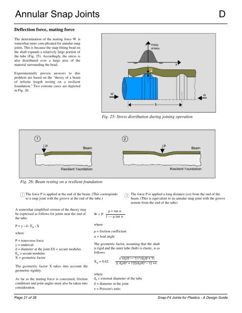
The determination of the mating <strong>for</strong>ce W is<br />
somewhat more com-plicated <strong>for</strong> annular snap<br />
joints. This is because the snap-fitting bead on<br />
the shaft expands a relatively large portion of<br />
the tube (Fig. 25). Accordingly, the stress is<br />
also distributed over a large area of the<br />
material surrounding the bead.<br />
Experimentally proven answers to this<br />
problem are based on the "theory of a beam<br />
of infinite length resting on a resilient<br />
foundation." Two extreme cases are depicted<br />
in Fig. 26.<br />
A somewhat simplified version of the theory may<br />
be expressed as follows <strong>for</strong> joints near the end of<br />
the tube:<br />
P=y• d • E s • X<br />
where<br />
22<br />
Fig. 26: Beam resting on a resilient foundation<br />
1<br />
The <strong>for</strong>ce P is applied at the end of the beam. (This corresponds<br />
to a snap joint with the groove at the end of the tube.)<br />
P = transverse <strong>for</strong>ce<br />
y = undercut<br />
d = diameter at the joint ES = secant modulus<br />
E s = secant modulus<br />
X = geometric factor<br />
The geometric factor X takes into account the<br />
geometric rigidity.<br />
As far as the mating <strong>for</strong>ce is concerned, friction<br />
conditions and joint angles must also be taken into<br />
consideration.<br />
W=P<br />
where<br />
µ + tan �<br />
1—µtan�<br />
µ = friction coefficient<br />
� = lead angle<br />
The geometric factor, assuming that the shaft<br />
is rigid and the outer tube (hub) is elastic, is as<br />
follows:<br />
X N = 0.62<br />
Fig. 25: Stress distribution during joining operation<br />
� (d 0/d — 1) / (d 0/d + 1)<br />
[( d 0/d) 2 + 1]/[(d 0/d) 2 –1]+�<br />
where<br />
d0 = external diameter of the tube<br />
d = diameter at the joint<br />
� = Poisson's ratio<br />
2<br />
The <strong>for</strong>ce P is applied a long distance (co) from the end of the<br />
beam. (This is equivalent to an annular snap joint with the groove<br />
remote from the end of the tube)<br />
Page 21 of 26 <strong>Snap</strong>-<strong>Fit</strong> <strong>Joints</strong> <strong>for</strong> <strong>Plastics</strong> - A <strong>Design</strong> <strong>Guide</strong>