Snap-Fit Joints for Plastics - A Design Guide - MIT
Snap-Fit Joints for Plastics - A Design Guide - MIT
Snap-Fit Joints for Plastics - A Design Guide - MIT

You also want an ePaper? Increase the reach of your titles
YUMPU automatically turns print PDFs into web optimized ePapers that Google loves.
<strong>Snap</strong> <strong>Joints</strong>/General A<br />
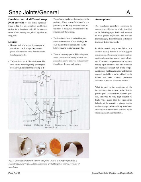
Combination of different snap<br />
joint systems – The traffic light illus-<br />
trated in Fig. 7 is an example of an effective<br />
design <strong>for</strong> a functional unit. All the components<br />
of the housing are joined together by<br />
snap joint.<br />
Details:<br />
• Housing and front access door engage at<br />
the fulcrum 1a. The lugs 1b (pressure<br />
point) hold the door open, which is useful<br />
<strong>for</strong> changing bulbs.<br />
• The cantilever hook 2 locks the door. The<br />
door can be opened again by pressing the<br />
hook through the slit in the housing at 2.<br />
8<br />
• The reflector catches at three points on the<br />
periphery. Either a snap-fittin hook 3a or a<br />
pressure point 3b may be chosen here, so<br />
that there is polygonal de<strong>for</strong>mation of the<br />
inner ring of the housing.<br />
• The lens in the front door is either pro<br />
duced in the second of two moldings 4a<br />
or, if a glass lens is desired, this can be<br />
held by several cantilever snaps 4b .<br />
• The sun visor engages at 5 like a bayonet<br />
catch. Good service-ability and low-cost<br />
production can be achieved with carefully<br />
thought-out designs such as this.<br />
Fig. 7: Cross-sectional sketch (above) and photo (below) of a traffic light made of<br />
Makrolon®polycarbonate. All the components are held together entirely be means of<br />
snap joints<br />
Assumptions<br />
The calculation procedures applicable to<br />
various types of joints are briefly described<br />
on the following pages, but in such a way as<br />
to be as general as possible. The user can<br />
there<strong>for</strong>e apply this in<strong>for</strong>mation to types of<br />
joints not dealt with directly.<br />
In all the snap-fit designs that follow, it is<br />
assumed initially that one of the mating parts<br />
remains rigid. This assumption represents an<br />
additional precaution against material failure.<br />
If the two com-ponents are of approximately<br />
equal stiffness, half the deflection<br />
can be assigned to each part. If one component<br />
is more rigid than the other and the total<br />
strength available is to be utilized to the<br />
fullest, the more complex procedure<br />
described in Section E must be adopted.<br />
What is said in the remainder of the<br />
brochure takes into account the fact that the<br />
plastics parts concerned are, <strong>for</strong> brief periods,<br />
subjected to very high mechanical<br />
loads. This means that the stress-strain<br />
behavior of the material is already outside<br />
the linear range and the ordinary modulus of<br />
elasticity must there<strong>for</strong>e be replaced by the<br />
strain dependent secant modulus.<br />
Page 7 of 26 <strong>Snap</strong>-<strong>Fit</strong> <strong>Joints</strong> <strong>for</strong> <strong>Plastics</strong> - A <strong>Design</strong> <strong>Guide</strong>