Snap-Fit Joints for Plastics - A Design Guide - MIT
Snap-Fit Joints for Plastics - A Design Guide - MIT
Snap-Fit Joints for Plastics - A Design Guide - MIT

Create successful ePaper yourself
Turn your PDF publications into a flip-book with our unique Google optimized e-Paper software.
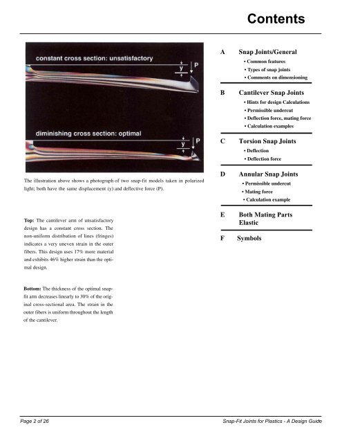
The illustration above shows a photograph of two snap-fit models taken in polarized<br />
light; both have the same displacement (y) and deflective <strong>for</strong>ce (P).<br />
Top: The cantilever arm of unsatisfactory<br />
design has a constant cross section. The<br />
non-uni<strong>for</strong>m distribution of lines (fringes)<br />
indicates a very uneven strain in the outer<br />
fibers. This design uses 17% more material<br />
and exhibits 46% higher strain than the optimal<br />
design.<br />
Bottom: The thickness of the optimal snapfit<br />
arm decreases linearly to 30% of the original<br />
cross-sectional area. The strain in the<br />
outer fibers is uni<strong>for</strong>m throughout the length<br />
of the cantilever.<br />
A <strong>Snap</strong> <strong>Joints</strong>/General<br />
• Common features<br />
Types of snap joints<br />
Comments on dimensioning<br />
B Cantilever <strong>Snap</strong> <strong>Joints</strong><br />
Hints <strong>for</strong> design Calculations<br />
Permissible undercut<br />
Deflection <strong>for</strong>ce, mating <strong>for</strong>ce<br />
Calculation examples<br />
C Torsion <strong>Snap</strong> <strong>Joints</strong><br />
Deflection<br />
Deflection <strong>for</strong>ce<br />
D Annular <strong>Snap</strong> <strong>Joints</strong><br />
Permissible undercut<br />
Mating <strong>for</strong>ce<br />
Calculation example<br />
E Both Mating Parts<br />
Elastic<br />
F Symbols<br />
Contents<br />
Page 2 of 26 <strong>Snap</strong>-<strong>Fit</strong> <strong>Joints</strong> <strong>for</strong> <strong>Plastics</strong> - A <strong>Design</strong> <strong>Guide</strong><br />
3