Snap-Fit Joints for Plastics - A Design Guide - MIT
Snap-Fit Joints for Plastics - A Design Guide - MIT
Snap-Fit Joints for Plastics - A Design Guide - MIT

You also want an ePaper? Increase the reach of your titles
YUMPU automatically turns print PDFs into web optimized ePapers that Google loves.
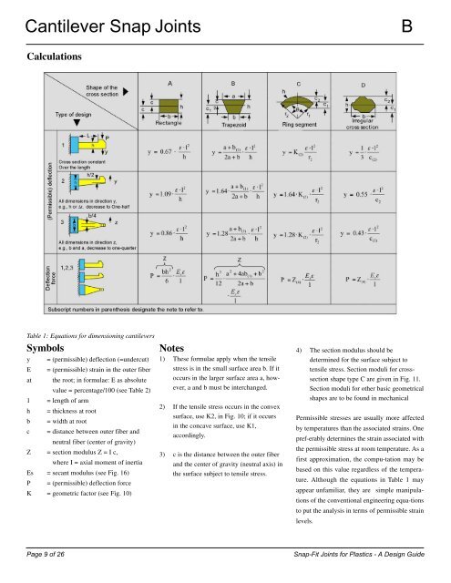
Cantilever <strong>Snap</strong> <strong>Joints</strong> B<br />
Calculations<br />
Table 1: Equations <strong>for</strong> dimensioning cantilevers<br />
Symbols<br />
y = (permissible) deflection (=undercut)<br />
E = (permissible) strain in the outer fiber<br />
at the root; in <strong>for</strong>mulae: E as absolute<br />
value = percentage/100 (see Table 2)<br />
1 = length of arm<br />
h = thickness at root<br />
b = width at root<br />
c = distance between outer fiber and<br />
neutral fiber (center of gravity)<br />
Z = section modulus Z = I c,<br />
where I = axial moment of inertia<br />
Es = secant modulus (see Fig. 16)<br />
P = (permissible) deflection <strong>for</strong>ce<br />
K = geometric factor (see Fig. 10)<br />
10<br />
Notes<br />
1) These <strong>for</strong>mulae apply when the tensile<br />
stress is in the small surface area b. If it<br />
occurs in the larger surface area a, however,<br />
a and b must be interchanged.<br />
2) If the tensile stress occurs in the convex<br />
surface, use K2, in Fig. 10; if it occurs<br />
in the concave surface, use K1,<br />
accordingly.<br />
3) c is the distance between the outer fiber<br />
and the center of gravity (neutral axis) in<br />
the surface subject to tensile stress.<br />
4) The section modulus should be<br />
determined <strong>for</strong> the surface subject to<br />
tensile stress. Section moduli <strong>for</strong> crosssection<br />
shape type C are given in Fig. 11.<br />
Section moduli <strong>for</strong> other basic geometrical<br />
shapes are to be found in mechanical<br />
Permissible stresses are usually more affected<br />
by temperatures than the associated strains. One<br />
pref-erably determines the strain associated with<br />
the permissible stress at room temperature. As a<br />
first approximation, the compu-tation may be<br />
based on this value regardless of the temperature.<br />
Although the equations in Table 1 may<br />
appear unfamiliar, they are simple manipulations<br />
of the conventional engineering equa-tions<br />
to put the analysis in terms of permissible strain<br />
levels.<br />
Page 9 of 26 <strong>Snap</strong>-<strong>Fit</strong> <strong>Joints</strong> <strong>for</strong> <strong>Plastics</strong> - A <strong>Design</strong> <strong>Guide</strong>