Snap-Fit Joints for Plastics - A Design Guide - MIT
Snap-Fit Joints for Plastics - A Design Guide - MIT
Snap-Fit Joints for Plastics - A Design Guide - MIT

You also want an ePaper? Increase the reach of your titles
YUMPU automatically turns print PDFs into web optimized ePapers that Google loves.
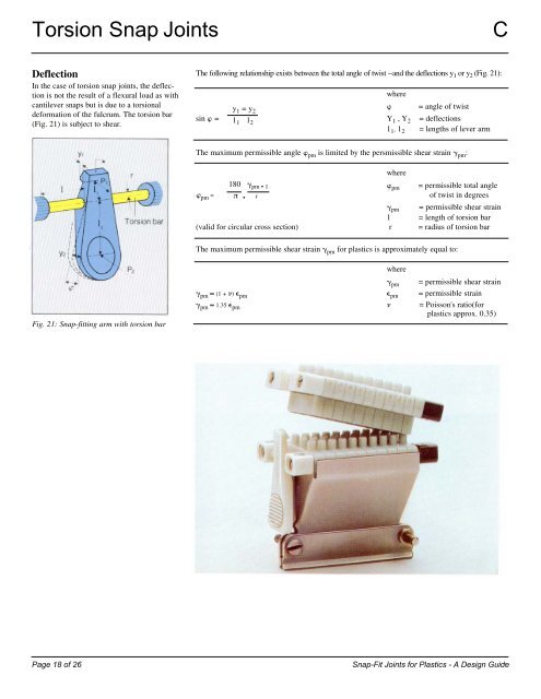
Torsion <strong>Snap</strong> <strong>Joints</strong> C<br />
Deflection<br />
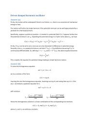
In the case of torsion snap joints, the deflection<br />
is not the result of a flexural load as with<br />
cantilever snaps but is due to a torsional<br />
de<strong>for</strong>mation of the fulcrum. The torsion bar<br />
(Fig. 21) is subject to shear.<br />
Fig. 21: <strong>Snap</strong>-fitting arm with torsion bar<br />
The following relationship exists between the total angle of twist --and the deflections y 1 or y 2 (Fig. 21):<br />
y1 =y2 where<br />
� = angle of twist<br />
sin � = 11 12 Y1 ,Y2 11 , 12 = deflections<br />
= lengths of lever arm<br />
The maximum permissible angle � pm is limited by the persmissible shear strain � pm :<br />
�pm =<br />
180 �pm • 1<br />
� • r<br />
where<br />
�pm = permissible total angle<br />
of twist in degrees<br />
�pm = permissible shear strain<br />
1 = length of torsion bar<br />
(valid <strong>for</strong> circular cross section) r = radius of torsion bar<br />
The maximum permissible shear strain � pm <strong>for</strong> plastics is approximately equal to:<br />
where<br />
�pm = permissible shear strain<br />
�pm � (1 + �) �pm �pm = permissible strain<br />
�pm � 1.35 �pm � = Poisson's ratio(<strong>for</strong><br />
plastics approx. 0.35)<br />
Page 18 of 26 <strong>Snap</strong>-<strong>Fit</strong> <strong>Joints</strong> <strong>for</strong> <strong>Plastics</strong> - A <strong>Design</strong> <strong>Guide</strong><br />
19