AuV - Uni Standard P2 - Layher
AuV - Uni Standard P2 - Layher
AuV - Uni Standard P2 - Layher

Create successful ePaper yourself
Turn your PDF publications into a flip-book with our unique Google optimized e-Paper software.
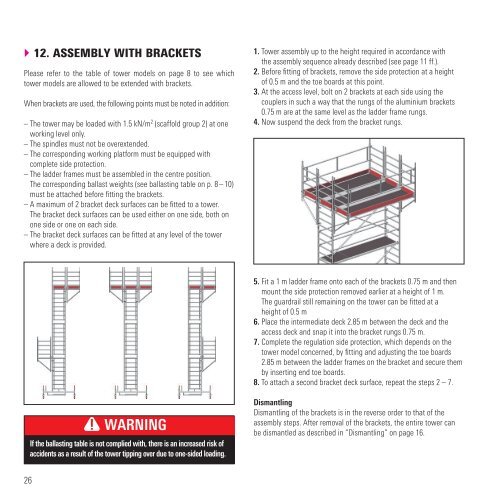
} 12. ASSEMBLY WITH BRACKETS<br />
Please refer to the table of tower models on page 8 to see which<br />
tower models are allowed to be extended with brackets.<br />
When brackets are used, the following points must be noted in addition:<br />
– The tower may be loaded with 1.5 kN/m 2 (scaffold group 2) at one<br />
working level only.<br />
– The spindles must not be overextended.<br />
– The corresponding working platform must be equipped with<br />
complete side protection.<br />
– The ladder frames must be assembled in the centre position.<br />
The corresponding ballast weights (see ballasting table on p. 8 – 10)<br />
must be attached before fitting the brackets.<br />
– A maximum of 2 bracket deck surfaces can be fitted to a tower.<br />
The bracket deck surfaces can be used either on one side, both on<br />
one side or one on each side.<br />
– The bracket deck surfaces can be fitted at any level of the tower<br />
where a deck is provided.<br />
26<br />
WARNING<br />
If the ballasting table is not complied with, there is an increased risk of<br />
accidents as a result of the tower tipping over due to one-sided loading.<br />
1. Tower assembly up to the height required in accordance with<br />
the assembly sequence already described (see page 11 ff.).<br />
2. Before fitting of brackets, remove the side protection at a height<br />
of 0.5 m and the toe boards at this point.<br />
3. At the access level, bolt on 2 brackets at each side using the<br />
couplers in such a way that the rungs of the aluminium brackets<br />
0.75 m are at the same level as the ladder frame rungs.<br />
4. Now suspend the deck from the bracket rungs.<br />
5. Fit a 1 m ladder frame onto each of the brackets 0.75 m and then<br />
mount the side protection removed earlier at a height of 1 m.<br />
The guardrail still remaining on the tower can be fitted at a<br />
height of 0.5 m<br />
6. Place the intermediate deck 2.85 m between the deck and the<br />
access deck and snap it into the bracket rungs 0.75 m.<br />
7. Complete the regulation side protection, which depends on the<br />
tower model concerned, by fitting and adjusting the toe boards<br />
2.85 m between the ladder frames on the bracket and secure them<br />
by inserting end toe boards.<br />
8. To attach a second bracket deck surface, repeat the steps 2 – 7.<br />
Dismantling<br />
Dismantling of the brackets is in the reverse order to that of the<br />
assembly steps. After removal of the brackets, the entire tower can<br />
be dismantled as described in “Dismantling” on page 16.