AuV - Uni Standard P2 - Layher
AuV - Uni Standard P2 - Layher
AuV - Uni Standard P2 - Layher

You also want an ePaper? Increase the reach of your titles
YUMPU automatically turns print PDFs into web optimized ePapers that Google loves.
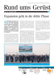
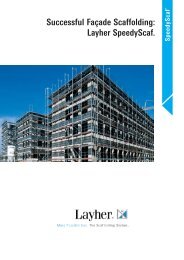
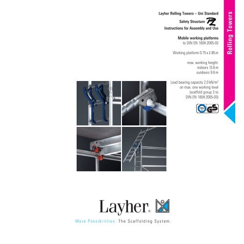
<strong>Layher</strong> Rolling Towers – <strong>Uni</strong> <strong>Standard</strong><br />
Safety Structure<br />
Instructions for Assembly and Use<br />
Mobile working platforms<br />
to DIN EN 1004:2005-03<br />
Working platform 0.75 x 2.85 m<br />
max. working height:<br />
indoors 13.6 m<br />
outdoors 9.6 m<br />
Load bearing capacity 2.0 kN/m 2<br />
on max. one working level<br />
(scaffold group 3 to<br />
DIN EN 1004:2005-03)<br />
Rolling Towers
} CONTENTS<br />
2<br />
1. Introduction ....................................................................4<br />
2. General directions for assembly and use ......................4<br />
3. Measures to prevent falls ..............................................6<br />
4. Tower models .................................................................8<br />
5. Assembly ......................................................................11<br />
6. Dismantling ..................................................................16<br />
7. Ascent via suspended ladder ......................................17<br />
8. Parts list ........................................................................18<br />
9. Ballasting ......................................................................20<br />
10. Stabilizer attachment ...................................................24<br />
11. Wall support and anchoring ........................................25<br />
12. Assembly with brackets ...............................................26<br />
13. Components of the system ..........................................27<br />
14. Certificate .....................................................................30<br />
15. Identification sign ........................................................31
} NOTE<br />
The products or assembly variants shown in these instructions for<br />
assembly and use may be subject to country-specific regulations. The<br />
user of the products bears the responsibility for compliance with such<br />
regulations. Subject to local regulations, we reserve the right not to<br />
supply all the products illustrated here.<br />
Your <strong>Layher</strong> partner on the spot will be happy to provide advice and<br />
answers to all questions relating to the approvals for the products, to<br />
their use or to specific assembly regulations.<br />
3
} 1. INTRODUCTION<br />
General<br />
These instructions for assembly and use relate to the assembly,<br />
modification and dismantling of the <strong>Layher</strong> <strong>Uni</strong> <strong>Standard</strong> rolling tower<br />
from Wilhelm <strong>Layher</strong> GmbH & Co. KG, of Gueglingen-Eibensbach,<br />
Germany. These instructions cannot cover all possible applications.<br />
If you have any questions about specific applications, please contact<br />
your <strong>Layher</strong> partner.<br />
Caution: <strong>Layher</strong> <strong>Uni</strong> <strong>Standard</strong> equipment may only be assembled,<br />
modified and dismantled under the supervision of a qualified expert<br />
and by technically trained employees.<br />
} 2. GENERAL DIRECTIONS<br />
FOR ASSEMBLY AND USE<br />
The rolling tower may be used for the scaffolding group as specified<br />
in DIN EN 1004.<br />
The user of the rolling tower must comply with the following<br />
instructions:<br />
1. The user must check the suitability of the selected rolling tower for<br />
the work to be performed (Section 4 of BetrSichV – German Ordinance<br />
on Industrial Safety and Health).<br />
2. According to DIN EN 1004:2005-03 the maximum platform height is<br />
• 12.0 m when inside buildings<br />
• 8.0 m when outside buildings<br />
The specifications governing ballasting and components on pages<br />
8 – 10 and 18 – 19 must be observed. There is a risk of accident if this<br />
is not done. Stability and load-bearing capacity are no longer assured.<br />
Any variations in assembly that differ from the specifications may<br />
require additional design measures. In such a case, the stability and<br />
load-bearing capacity would have to be verified for the individual case.<br />
3. The assembly, modification or dismantling of the rolling tower in<br />
accordance with the present instructions for assembly and use may<br />
only be performed under the supervision of a qualified expert and<br />
by technically trained employees after special instruction. Only the<br />
4<br />
scaffolding types shown in these instructions for assembly and use<br />
may be used. After assembly and before being put into service, the<br />
equipment must be inspected by persons qualified to do so (Sections<br />
4 and 10 of BetrSichV). The inspection must be documented (Section<br />
11 of BetrSichV). During assembly, modification or dismantling, the<br />
rolling tower must be provided with a prohibition sign indicating “No<br />
access allowed” and be adequately safeguarded by means of barriers<br />
preventing access to the danger zone (BetrSichV Annex 2, para. 5.2.5).<br />
4. Before installation, all parts must be inspected to ensure they are in<br />
perfect condition. Only undamaged original parts from <strong>Layher</strong>‘s mobile<br />
working platform systems may be used. Scaffolding parts such as snapon<br />
claws and spigots must be cleaned of dirt after use. Scaffolding<br />
components must be secured against slipping and impacts when transported<br />
by truck. Scaffolding components must be handled in such a way<br />
that they are not damaged. See the tables on pages 8 – 10 of these<br />
instructions for wall bracing and attachment of the ballast weights.<br />
5. In order to assemble the upper sections of the rolling tower, the<br />
individual parts must be handed up from one level to the next. Tools<br />
and small amounts of materials can be carried up by the personnel,<br />
otherwise hoisted up to the working level using transport ropes.<br />
6. The ladder frame joints must always be secured with locking pins.<br />
7. Suitable materials must be inserted underneath to ensure that<br />
the scaffolding is perpendicular. The permitted deviation from the<br />
perpendicular must not be more than 1 %.<br />
8. Stability must be ensured at every phase of assembly.<br />
9. Toe boards can be omitted from intermediate platforms that are only<br />
used for ascent. Small towers in which the deck surface is more than<br />
1.00 m high must include equipment that permits attachment of side<br />
protection in accordance with DIN EN 1004:2005-03.<br />
10. Access up to the working platform is generally only permitted on the<br />
inside of the scaffolding. Scaffolding types with an assembly height of<br />
less than 1 m are an exception to this rule.<br />
11. Work must not take place on two or more working levels at the same<br />
time. The manufacturer must be consulted regarding any variations. If<br />
work is to take place on more than one level, they must be fully fitted<br />
with 3-piece side protection.
12. It is not permitted to push against adjacent objects (such as walls)<br />
when working on mobile working platforms.<br />
13. Lifting gear must not be attached to or used on mobile working<br />
platforms.<br />
14. Assembly and movement is only permitted on sufficiently strong<br />
surfaces, and only in the longitudinal direction or diagonally. All impacts<br />
must be avoided. If the base is widened on one side with wall bracing,<br />
movement must always be parallel to the wall. Movement should not<br />
be faster than normal walking pace.<br />
15. No personnel and/or loose objects may be on the tower while it is<br />
being moved.<br />
16. After movement, the wheels must be locked by pressing down the<br />
brake lever.<br />
17. The towers must not be subjected to any aggressive fluids or gases.<br />
18. Mobile working platforms must not be connected by bridging unless<br />
a special verification of structural stability is provided. The same applies<br />
to all special structures such as suspended scaffolding. The attachment<br />
of any bridging elements between one mobile working platform and a<br />
building is also not permitted.<br />
19. When used in the open air, or in open buildings, the mobile<br />
working platform must be moved to an area protected from the wind<br />
or secured by other suitable means to prevent it falling over if the<br />
wind strength exceeds 6 on the Beaufort scale, or at the end of the<br />
working shift. (Wind that exceeds strength 6 can be recognized from<br />
the difficulty felt when walking into the wind.) If possible, rolling towers<br />
used outside buildings should be securely fastened to the building or to<br />
some other structure. It is recommended that mobile working platforms<br />
are anchored down if they are left unsupervised. The scaffolding must<br />
be aligned perpendicular either by use of the compensating screw, or by<br />
inserting suitable materials underneath. The permitted deviation from<br />
the perpendicular must not be more than 1 %.<br />
20. Decks can also be raised or lowered one rung in order to obtain a<br />
different working height. In that case it is necessary to make sure that<br />
the specified side protection heights of 1.0 m and 0.5 m are maintained.<br />
When assembled this way, deck diagonals are to be used.<br />
The manufacturer must be consulted regarding a stability<br />
verification.<br />
21. The access hatches must always be kept closed except when<br />
climbing through them.<br />
22. All couplers are to be tightened up to 50 Nm.<br />
23. It is forbidden to climb over from rolling towers.<br />
24. Jumping onto the deck surfaces is forbidden.<br />
25. A check must be made on whether all the parts, auxiliary tools<br />
and safety equipment (ropes etc.) needed for assembly of the mobile<br />
working platforms are available on the building site.<br />
26. Horizontal and vertical loads that could cause the mobile working<br />
platform to tip over must be avoided. These include:<br />
– forces caused by pushing against adjacent objects (e.g. walls)<br />
– additional wind loads (the tunnel effect of buildings with throughpassages,<br />
buildings without facings or building corners).<br />
27. Mobile beams, stabilizers or outriggers and ballast must be installed<br />
if specified.<br />
28. It is forbidden to increase the height of the deck surfaces by using<br />
ladders, boxes or any other objects.<br />
29. Mobile working platforms are not designed to be lifted or<br />
suspended.<br />
30. The item numbers for components given in blue in the text refer to<br />
the list of individual parts on pages 27 – 29.<br />
5
} 3. MEASURES TO PREVENT FALLS<br />
Preventing falls during assembly,<br />
modification or dismantling of the tower<br />
General<br />
In line with local regulations or as the result of a risk analysis performed<br />
by the scaffolding erector, personal safety apparatus (PSA), an assembly<br />
guardrail or a combination of the two may be necessary for assembly,<br />
modification or dismantling of the scaffolding.<br />
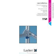
Attachment points on the tower for the personal<br />
safety apparatus (PSA)<br />
The tower can be assembled/dismantled optionally with personal<br />
safety apparatus (PSA) too. Suspend the snap hook during ascent<br />
at least 1.0 m above the standing area of the still unsecured level.<br />
The platform height must be at least 5.75 m. This results in a<br />
minimum attachment height for the PSA of 6.75 m (Fig. 1).<br />
Fig. 2: Minimum heights for use of PSA<br />
The tower level can then be secured with the rear guardrails.<br />
Fig. 1: Attachment of PSA during ascent onto the unsecured level Fig. 3: Safe assembly of rear guardrails using PSA<br />
6<br />
1.00 m<br />
5.75 m<br />
Standing area
How the <strong>Layher</strong> advance guardrail system works<br />
The <strong>Layher</strong> advance guardrail consists of two basic components –<br />
advance guardrail post and telescoping guardrail. The assembly post<br />
a) or b) must be used depending on local regulations.<br />
a. Advance guardrail post with connection for telescoping guardrail<br />
at 1 m height<br />
b. Advance guardrail post with connection for telescoping guardrail<br />
at 0.5 m and 1 m heights<br />
c. Advance telescopic guardrail of aluminium<br />
a b c<br />
The advance guardrail post of the assembly safety<br />
rail can be fitted and dismantled by an erector from two<br />
positions:<br />
1. Assembly/dismantling from above<br />
2. Assembly/dismantling from below<br />
Ensure that both claws of the advance guardrail snap<br />
in completely and that the telescoping guardrail is<br />
attached using the tilting pins.<br />
To prevent unintended slipping of<br />
the advance guardrail post, fit a rear<br />
guardrail at the level of a snap-on<br />
claw.<br />
Fig. 4: Connection of advance guardrail post to the ladder frame<br />
Fig. 5: Upward movement of the advance guardrail system<br />
Fig. 6: Safe assembly of rear guardrails using advance guardrail system<br />
7
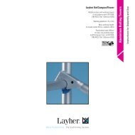
} 4. TOWER MODELS<br />
In the case of assembly outdoors, do not exceed the height limit!<br />
Tower models<br />
1401101 – 1401111<br />
Working height<br />
Scaffolding<br />
height<br />
Platform<br />
height<br />
1401101 1401102 1401103 1401104<br />
1401105 1401106 1401107 1401108 1401109 1401110 1401111<br />
Tower model 1401101 1401102 1401103 1401104 1401105 1401106 1401107 1401108 1401109 1401110 1401111<br />
Working height [m] 3.5 4.5 5.5 6.5 7.5 8.5 9.6 10.6 11.6 12.6 13.6<br />
Scaffolding height [m] 2.6 3.75 4.75 5.75 6.75 7.75 8.79 9.79 10.79 11.79 12.79<br />
Platform height [m] 1.5 2.5 3.5 4.5 5.5 6.5 7.6 8.6 9.6 10.6 11.6<br />
Weight [kg] (without ballast)<br />
Ballasting<br />
Indoors<br />
85.6 184.0 218.9 245.8 280.7 307.6 393.7 420.6 455.5 482.4 517.3<br />
Assembly central l2 r2 0 0 0 0 0 0 0 0 0 0<br />
Assembly off-set X 0 0 L0 R4 L0 R4 L0 R6 L0 R4 L0 R6 L0 R6 L0 R8 L0 R10<br />
Assembly off-set with wall bracing X 0 0 0 0 0 0 0 0 0 0<br />
Assembly central with 1 bracket X 0 0 L0 R2 L0 R4 L0 R6 0 0 0 0 0<br />
Assembly central with 2 brackets<br />
Outdoors<br />
X 0 0 0 0 0 0 0 0 0 0<br />
Assembly central l2 r2 0 l1 r1 l5 r5 l9 r9 l15 r15 l2 r2 X X X X<br />
Assembly off-set X L0 R2 L0 R6 L0 R10 L4 R16 L10 R22 L0 R18 X X X X<br />
Assembly off-set with wall bracing X 0 0 0 L4 R0 L10 R0 0 X X X X<br />
Assembly central with 1 bracket X L0 R4 L0 R8 L0 R2 L0 R16 L12 R12 X X X X X<br />
Assembly central with 2 brackets X l2 r2 l5 r5 l8 r8 X X X X X X X<br />
When assembling with adjustable mobile beam, it must be fully extended. X = not permissible / possible 0 = no ballast required Table gives the number of ballast weights each of 10 kg.<br />
For ballasting, use <strong>Layher</strong> ballast weights, Ref. No. 1249.000, 10 kg each. These are fastened quickly and securely at the right place using the star handle coupling.<br />
Liquid or granular ballast materials must not be used. The ballast weights must be distributed evenly to all ballast fixing points (see pages 20 – 23).<br />
Example: l2, r2 � 2 ballast weights of 10 kg each must be fastened to the left-hand side of the ladder frame, and 2 ballast weights of 10 kg each to its right-hand side<br />
L6, R16 � 6 ballast weights of 10 kg each must be fastened to the left-hand side of the mobile beam, and 16 ballast weights of 10 kg each to its right-hand side<br />
8<br />
r and R always relate, in the case of off-centre assembly, to that side facing away from the scaffolding; l and L relate to the side facing the scaffolding (see also Section 9, Ballasting, on pages 20 – 23)
} TOWER MODELS WITH STABILIZERS, EXTENDABLE<br />
In the case of assembly outdoors, do not exceed the height limit!<br />
Tower models<br />
1401124 – 1401131<br />
Working height<br />
Scaffolding<br />
height<br />
Platform<br />
height<br />
1401124 1401125<br />
1401126 1401127 1401128 1401129 1401130 1401131<br />
Tower model 1401124 1401125 1401126 1401127 1401128 1401129 1401130 1401131<br />
Working height [m] 6.5 7.5 8.5 9.5 10.5 11.5 12.5 13.5<br />
Scaffolding height [m] 5.7 6.7 7.7 8.7 9.7 10.7 11.7 12.7<br />
Platform height [m] 4.5 5.5 6.5 7.5 8.5 9.5 10.5 11.5<br />
Weight [kg] (without ballast)<br />
Ballasting<br />
Indoors<br />
234.7 286.0 296.5 347.8 358.3 409.6 420.1 471.4<br />
Assembly central 0 0 0 0 0 0 0 0<br />
Assembly off-set L0 R6 L0 R8 L0 R12 L0 R12 L0 R16 L0 R18 L0 R20 L0 R22<br />
Assembly off-set with wall bracing<br />
Outdoors<br />
0 0 0 0 0 0 0 0<br />
Assembly central 0 0 0 0 X X X X<br />
Assembly off-set L0 R16 L0 R20 L0 R28 L0 R34 X X X X<br />
Assembly off-set with wall bracing 0 0 0 0 X X X X<br />
When assembling with adjustable mobile beam, it must be fully extended. X = not permissible / possible 0 = no ballast required Table gives the number of ballast weights each of 10 kg.<br />
For ballasting, use <strong>Layher</strong> ballast weights, Ref. No. 1249.000, 10 kg each. These are fastened quickly and securely at the right place using the star handle coupling.<br />
Liquid or granular ballast materials must not be used. The ballast weights must be distributed evenly to all ballast fixing points (see pages 20 – 23).<br />
Example: l2, r2 � 2 ballast weights of 10 kg each must be fastened to the left-hand side of the ladder frame, and 2 ballast weights of 10 kg each to its right-hand side<br />
L6, R16 � 6 ballast weights of 10 kg each must be fastened to the left-hand side of the stabilizers, and 16 ballast weights of 10 kg each to its right-hand side<br />
r and R always relate, in the case of off-centre assembly, to that side facing away from the scaffolding; l and L relate to the side facing the scaffolding (see also Section 9, Ballasting, on pages 20 – 23)<br />
9
} TOWER MODELS WITH STABILIZERS, 5 M<br />
In the case of assembly outdoors, do not exceed the height limit!<br />
Tower models<br />
1401145 – 1401151<br />
Working height<br />
Scaffolding<br />
height<br />
Platform<br />
height<br />
10<br />
1401145 1401146<br />
1401147 1401148 1401149 1401150 1401151<br />
Tower model 1401145 1401146 1401147 1401148 1401149 1401150 1401151<br />
Working height [m] 7.5 8.5 9.5 10.5 11.5 12.5 13.5<br />
Scaffolding height [m] 6.7 7.7 8.7 9.7 10.7 11.7 12.7<br />
Platform height [m] 5.5 6.5 7.5 8.5 9.5 10.5 11.5<br />
Weight [kg] (without ballast)<br />
Ballasting<br />
Indoors<br />
311.6 322.1 373.4 383.9 435.2 445.7 497.0<br />
Assembly central 0 0 0 0 0 0 0<br />
Assembly off-set L0 R6 L0 R8 L0 R8 L0 R10 L0 R12 L0 R14 L0 R14<br />
Assembly off-set with wall bracing<br />
Outdoors<br />
0 0 0 0 0 0 0<br />
Assembly central 0 0 0 X X X X<br />
Assembly off-set L0 R16 L0 R20 X X X X X<br />
Assembly off-set with wall bracing 0 0 0 X X X X<br />
When assembling with adjustable mobile beam, it must be fully extended. X = not permissible / possible 0 = no ballast required Table gives the number of ballast weights each of 10 kg.<br />
For ballasting, use <strong>Layher</strong> ballast weights, Ref. No. 1249.000, 10 kg each. These are fastened quickly and securely at the right place using the star handle coupling.<br />
Liquid or granular ballast materials must not be used. The ballast weights must be distributed evenly to all ballast fixing points (see pages 20 – 23).<br />
Example: l2, r2 � 2 ballast weights of 10 kg each must be fastened to the left-hand side of the ladder frame, and 2 ballast weights of 10 kg each to its right-hand side<br />
L6, R16 � 6 ballast weights of 10 kg each must be fastened to the left-hand side of the stabilizers, and 16 ballast weights of 10 kg each to its right-hand side<br />
r and R always relate, in the case of off-centre assembly, to that side facing away from the scaffolding; l and L relate to the side facing the scaffolding (see also Section 9, Ballasting, on pages 20 – 23)
} 5. ASSEMBLY Safety Structure <strong>P2</strong><br />
Observe the general directions for assembly and use on pages 4 – 5. The<br />
assembly examples shown are intended for use indoors up to a maximum<br />
platform height of 12 m and outdoors up to a maximum platform height of<br />
8 m. Snap the snap-on claws of all parts into the ladder frames from above.<br />
Level the tower after the basic assembly process. This is done using the<br />
threaded spindles of the castors 1.<br />
The castors must be locked during assembly, modification or<br />
dismantling, and when there are people on the scaffolding.<br />
Wedges in the system must be hammered home until the blow<br />
bounces off. Screw couplers must generally be tightened (50 Nm).<br />
On the topmost scaffolding level, a double guardrail 16 or a tower<br />
beam 17 can be fitted instead of two rear guardrails. Please remember<br />
in this case that for assembly and dismantling two additional rear<br />
guardrails must be present to ensure collective side protection. These<br />
can be removed again after insertion of the double guardrail or of the<br />
tower beam.<br />
The item numbers of the parts relate to the individual part list on page<br />
27 – 29.<br />
Basic assembly<br />
Tower model 1401101<br />
1. Insert the castors 1 into the 2.00 m ladder frames 13 and secure<br />
them against falling out by fastening the wing screws on the spindle<br />
nuts.<br />
2. Connect the two ladder frames 13 using two double guardrails 16.<br />
Suspend the access deck 23 from the fourth rung from below of the<br />
2.00 m ladder frames 13.<br />
Basic assembly<br />
Tower models 1401102, 1401104, 1401106,<br />
1401108 and 1401110<br />
1. Insert the castors 1 into the mobile beams 5/6 and secure them<br />
against falling out by fastening the wing screws on the spindle<br />
nuts.<br />
2. Connect the mobile beams 5/6 using a basic tube 7 / basic strut 8<br />
and a deck 24.<br />
3. Fit two 1.00 m ladder frames 12 onto the mobile beams and<br />
secure them using spring clips 14.<br />
Further assembly is in accordance with page 13 “Assembly of intermediate<br />
platforms”.<br />
11
Basic assembly<br />
Tower models 1401103, 1401105, 1401107,<br />
1401109 and 1401111<br />
1. Insert the castors 1 into the mobile beams 5/6 and secure them against<br />
falling out by fastening the wing screws on the spindle nuts.<br />
2. Connect the mobile beams 5/6 using a basic tube 7 / basic strut 8<br />
and a rear guardrail 15 to the bar of the mobile beam.<br />
3. Fit a 2.00 m ladder frame 13 onto the mobile beam 5/6 and secure<br />
it with spring clips 14. Suspend two rear guardrails 15 from the top<br />
rung and connect them with a second 2.00 m ladder frame 13. Then fit<br />
the second 2.00 m ladder frame 13 onto the mobile beam and secure<br />
it using spring clips 14. (Any double guardrails in stock must be installed<br />
as side protection for the first level. The rear guardrails previously<br />
installed as an advance side protection are removed again after the<br />
double guardrails have been fitted.)<br />
4. Fit two diagonal braces 19 and the access deck 23. Ensure here that<br />
the two diagonal braces are installed parallel to one another in the<br />
direction of the access hatch.<br />
5. Climb up to the next level and fit additional rear guardrails 15 to the<br />
second rung above the platform surface.<br />
Further assembly is in accordance with page 13 “Assembly of intermediate<br />
platforms”.<br />
12<br />
Basic assembly<br />
Tower models 1401124, 1401126, 1401128, 1401130,<br />
1401146, 1401148 and 1401150<br />
1. Insert the castors 1 into the 1.00 m ladder frames 12 and secure them<br />
against falling out by fastening the wing screws on the spindle nuts.<br />
2. Fit further 2.00 m ladder frames 13. Connect the two rolling tower<br />
side parts to the top rungs and to the bottom rungs, using two rear<br />
guardrails 15 in each case.<br />
3. Install two diagonal braces 18 crosswise. Then suspend an access<br />
deck 23.<br />
4. To keep to the maximum spacing from the first rung, fit an access<br />
ledger 9 on the access side of the rolling tower.<br />
5. Climb up to the next level and fit additional rear guardrails 15 to the<br />
second rung above the platform surface.<br />
Further assembly is in accordance with page 13 “Assembly of intermediate<br />
platforms”.
Basic assembly<br />
Tower models 1401125, 1401127, 1401129, 1401131,<br />
1401145, 1401147, 1401149 and 1401151<br />
1. Insert the castors 1 into the 2.00 m ladder frames 13 and secure them<br />
against falling out by fastening the wing screws on the spindle nuts.<br />
2. Connect the two rolling tower side parts to the top rungs and to the<br />
bottom rungs, using two rear guardrails 15 in each case.<br />
3. Fit two diagonal braces 19 and the access deck 23. Ensure here that<br />
the two diagonal braces are installed parallel to one another in the<br />
direction of the access hatch.<br />
4. To keep to the maximum spacing from the first rung, fit an access<br />
ledger 9 on the access side of the rolling tower.<br />
5. Climb up to the next level and fit additional rear guardrails 15 to the<br />
second rung above the platform surface. (Any double guardrails 16 in<br />
stock must be installed as side protection for the first level. The rear<br />
guardrails previously installed as an advance side protection are removed<br />
again after the double guardrails have been fitted.)<br />
Further assembly is in accordance with “Assembly of intermediate<br />
platforms” (see on the right side).<br />
Assembly of intermediate platforms<br />
All tower models<br />
The following assembly steps 1 to 5 are repeated several<br />
times depending on the assembly height.<br />
1. Fit the first 2.00 m ladder frame 13 and secure it with spring clips 14.<br />
2. Attach the <strong>Uni</strong> assembly hook 25 and position the second ladder<br />
frame 13 for fitting the rear guardrails 15.<br />
3. Swing the ladder frame with the rear guardrail upwards, fit it in place<br />
and secure it with spring clips 14.<br />
13
4. Insert diagonal braces 18 and an access deck 23. The diagonal<br />
braces must be installed in a tower-like (zig-zag) form on both sides.<br />
5. Climb up to the next level and fit additional rear guardrails 15 to the<br />
second rung above the platform surface.<br />
14<br />
Completion of working platform<br />
All tower models<br />
1. To complete the working platform, attach toe boards with claw 28<br />
and end toe boards 29.<br />
If an intermediate platform is also to be used as a working<br />
platform, attach toe boards here too.<br />
Operating the castors<br />
During assembly and while working, keep<br />
the castors locked by pressing down the<br />
brake lever labelled STOP.<br />
When the brake is locked, the lever<br />
labelled STOP is in the down position.<br />
For movement, unlock the castors by<br />
pushing the opposite lever down.
max.<br />
15 cm<br />
max.<br />
15 cm<br />
Adjustment of the mobile beam<br />
1<br />
5<br />
Models: 1401108, 1401110<br />
K<br />
M S<br />
Maximum spindle adjustment<br />
of the various models<br />
Assembly with 1323.180<br />
max.<br />
40 cm<br />
Models: 1401102, 1401104, 1401106<br />
Assembly with 1323.320<br />
max.<br />
40 cm<br />
max.<br />
60 cm<br />
V<br />
max.<br />
30 cm<br />
Models: 1401103, 1401105<br />
max.<br />
60 cm<br />
The adjustable mobile beam 5 permits operation in the centre position<br />
and at the wall without dismantling the scaffolding. It can be retracted<br />
and extended in the assembled state. Ensure before adjustment the<br />
ballast weights specified in the ballasting table are always attached<br />
at the right place (see pages 8 –10). For adjustment in the assembled<br />
state, lower the central support M attached to the mobile beam 5 as<br />
far as possible and secure it. Relieve the castors 1 at the sliding parts<br />
by turning the spindle S until the adjustment part V can be adjusted<br />
when the clamping wedge K has been loosened. After adjustment, fix<br />
the clamping wedge K, subject the castor 1 to load again by turning<br />
the spindle, and move the central support M upwards and secure it.<br />
max.<br />
30 cm<br />
Models: 1401109, 1401111<br />
Assembly directly on castors with<br />
access ledger<br />
max. 20 cm<br />
max.<br />
40 cm<br />
Models: 1401101<br />
(access ledger add. required)<br />
1401124 – 1401131<br />
1401145 – 1401151<br />
Assembly directly on castors<br />
0 cm<br />
Model: 1401101<br />
max.<br />
40 cm<br />
15
} 6. DISMANTLING<br />
Dismantling is in the reverse order to assembly (see page 11 –15).<br />
When dismantling, do not remove the bracing elements such as<br />
diagonal braces, rear guardrails or access decks until the ladder<br />
frames above them have been dismantled.<br />
To lift out the individual parts, open the snap-on claws by pressing<br />
their locking clips.<br />
16<br />
During dismantling of an intermediate or working platform, first remove<br />
the topmost rear guardrails from the level underneath them. This is<br />
done with the aid of a rear guardrail installed at knee level.<br />
It is placed from above onto the 2nd rung and acts as a lever for opening<br />
the snap-on claw (see detail).<br />
The red locking clips of the decks permit effortless installation and<br />
removal by a single person; first open them and place the deck with<br />
the opened clips on the rung, then open the opposite clips and lift out<br />
the deck.
} 7. ASCENT VIA SUSPENDED LADDER<br />
The types 1401102 – 1401111, 1401124 – 1401131 and 1401145 – 1401151<br />
can easily be equipped with the scaffolding access ladder 33 to provide<br />
more convenient access. The ladder is simply dropped into the<br />
8th rung of the ladder frame (deck level) on the access hatch side and<br />
placed on the deck below.<br />
17
} 8. PARTS LIST<br />
Tower model Ref. No. 1401101 1401102 1401103 1401104 1401105 1401106 1401107 1401108 1401109 1401110 1401111<br />
Guardrail 2.85 m 1205.285 0 4 9 8 13 12 17 16 21 20 25<br />
Double guardrail 2.85 m 1206.285 2 0 0 0 0 0 0 0 0 0 0<br />
Diagonal brace 3.35 m 1208.285 0 2 2 4 4 6 6 8 8 10 10<br />
Diagonal brace 2.95 m 1208.295 0 0 2 0 2 0 2 0 2 0 2<br />
Basic tube 2.85 m 1211.285 0 1 1 1 1 1 1 1 1 1 1<br />
End toe board 0.75 m 1238.075 0 2 2 2 2 2 2 2 2 2 2<br />
Toe board 2.85 m, with claw 1239.285 0 2 2 2 2 2 2 2 2 2 2<br />
Deck 2.85 m 1241.285 0 1 0 1 0 1 0 1 0 1 0<br />
Access deck 2.85 m 1242.285 1 1 2 2 3 3 4 4 5 5 6<br />
Spring clip 11 mm 1250.000 0 8 8 12 12 16 16 20 20 24 24<br />
Castor 700 – 7 kN 1259.200 4 4 4 4 4 4 4 4 4 4 4<br />
Ladder frame 75/4 – 1.00 m 1297.004 0 2 0 2 0 2 0 2 0 2 0<br />
Ladder frame 75/8 – 2.00 m 1297.008 2 2 4 4 6 6 8 8 10 10 12<br />
Mobile beam with bar 1323.180 0 2 2 2 2 2 0 0 0 0 0<br />
Mobile beam with bar, adjustable 1323.320 0 0 0 0 0 0 2 2 2 2 2<br />
<strong>Uni</strong> assembly hook 1300.001 0 1 1 1 1 1 1 1 1 1 1<br />
Ballast 1249.000 For the number of ballasting weights see the ballasting table, see pages 8 – 10<br />
Assembly variants with stabilizers, extendable: 1124 – 1131; with stabilizer, 5 m: 1145 – 1151<br />
Tower model Ref. No. 1401124 1401125 1401126 1401127 1401128 1401129 1401130 1401131 1401145 1401146 1401147 1401148 1401149 1401150 1401151<br />
Guardrail 2.85 m 1205.285 10 14 14 18 20 22 22 26 14 14 18 20 22 22 26<br />
Diagonal brace 3.35 m 1208.285 4 4 6 6 8 8 10 10 4 6 6 8 8 10 10<br />
Diagonal brace 2.95 m 1208.295 0 2 0 2 0 2 0 2 2 0 2 0 2 0 2<br />
End toe board 0.75 m 1238.075 2 2 2 2 2 2 2 2 2 2 2 2 2 2 2<br />
Toe board 2.85 m, with claw 1239.285 2 2 2 2 2 2 2 2 2 2 2 2 2 2 2<br />
Access deck 2.85 m 1242.285 2 3 3 4 4 5 5 6 3 3 4 4 5 5 6<br />
Stabilizer, extendable 1248.260 4 4 4 4 4 4 4 4 0 0 0 0 0 0 0<br />
Tower rotation lock 1248.261 4 4 4 4 4 4 4 4 4 4 4 4 4 4 4<br />
Stabilizer, 5 m 1248.500 0 0 0 0 0 0 0 0 4 4 4 4 4 4 4<br />
Spring clip 11 mm 1250.000 12 12 16 16 20 20 24 24 12 16 16 20 20 24 24<br />
Castor 700 – 7 kN 1259.200 4 4 4 4 4 4 4 4 4 4 4 4 4 4 4<br />
Ladder frame 75/4 – 1.00 m 1297.004 2 0 2 0 2 0 2 0 0 2 0 2 0 2 0<br />
Ladder frame 75/8 – 2.00 m 1297.008 4 6 6 8 8 10 10 12 6 6 8 8 10 10 12<br />
Access ledger 1344.002 1 1 1 1 1 1 1 1 1 1 1 1 1 1 1<br />
<strong>Uni</strong> assembly hook 1300.001 1 1 1 1 1 1 1 1 1 1 1 1 1 1 1<br />
Ballast 1249.000 For the number of ballasting weights see the ballasting table, see pages 8 –10<br />
18
Additional requirement for special structure with bracket deck surfaces<br />
Tower model Ref. No. 1 bracket deck surface 2 bracket deck surfaces<br />
End toe board 0.75 m 1238.075 2 4<br />
Deck 2.85 m 1241.285 1 2<br />
Spring clip 1250.000 4 8<br />
Ladder frame 75/4 1297.004 2 4<br />
Intermediate deck 1339.285 1 2<br />
Aluminium bracket 0.75 m 1341.075 4 4<br />
The tower models, which can be extended with bracket deck surfaces are shown on pages 8 – 10 (Ballasting). When operating with<br />
brackets, the tower may be loaded with 1.5 kN/m 2 (scaffold group 2) at one working level only. A maximum of 2 bracket deck surfaces<br />
may be assembled. When bracket deck surfaces are fitted, the spindles mustn‘t be extended. The corresponding working level must be equipped<br />
with complete side protection.<br />
19
} 9. BALLASTING<br />
Attachment of ballast weights<br />
Assembly central:<br />
Model:<br />
1401101<br />
l r<br />
l<br />
20<br />
l r<br />
r<br />
Models:<br />
1401102 – 1401106<br />
L l r R<br />
L<br />
l r<br />
l r<br />
L R<br />
Models:<br />
1401107 – 1401111<br />
l r<br />
L R<br />
R<br />
L<br />
Models:<br />
1401124 – 1401131<br />
1401145 – 1401151<br />
L<br />
l<br />
l<br />
l<br />
L R<br />
r<br />
r<br />
r<br />
R<br />
R
Assembly off-set:<br />
L l r R L l r<br />
L<br />
l r<br />
Models:<br />
1401102 – 1401106<br />
L R<br />
R<br />
L<br />
l r<br />
Models:<br />
1401107 – 1401111<br />
l r l r<br />
L R<br />
R<br />
R<br />
l<br />
l<br />
L<br />
L<br />
L<br />
Models:<br />
1401124 – 1401131<br />
1401145 – 1401151<br />
l r<br />
r<br />
r<br />
R<br />
R<br />
R<br />
21
Assembly central with brackets:<br />
l r<br />
L R<br />
L R<br />
l r<br />
l r<br />
l r<br />
L R L R<br />
22<br />
l r<br />
L R<br />
L R<br />
l r
Example for assembly, model 1401104<br />
Assembly outdoors in off-centre position<br />
Ballast: see page 8<br />
Tower model 1401104<br />
Working height [m] 6.5<br />
Scaffolding height [m] 5.75<br />
Platform height [m] 4.5<br />
Weight [kg] (without ballast) 245.8<br />
Ballasting<br />
Indoors<br />
Assembly central 0<br />
Assembly off-set L0 R4<br />
Assembly off-set with wall bracing 0<br />
Assembly central with 1 bracket L0 R2<br />
Assembly central with 2 brackets 0<br />
Outdoors<br />
Assembly central l5 r5<br />
Assembly off-set L0 R10<br />
Assembly off-set with wall bracing 0<br />
Assembly central with 1 bracket L0 R2<br />
Assembly central with 2 brackets l8 r8<br />
23
} 10. STABILIZER ATTACHMENT<br />
Read and understand “Basic Assembly for Rolling Tower Types<br />
Without Mobile Beams” on pages 12 – 13 before assembly. The fixed<br />
and adjustable mobile beams are not included when assembled this<br />
way. They are replaced by extendable stabilizers 30.<br />
Attach a stabilizer 30/31 to every stile of the ladder frame 13. To do<br />
so, attach the half-coupler directly underneath the rung of the ladder<br />
frame 13 . Before tightening the star-knobs (hand wheels), fix the stabilizers<br />
in the correct position against the wall, or free-standing, then<br />
tighten using the star-knobs. Move the half-coupler on the stabilizer<br />
to make sure that the foot is standing firmly on the ground. Fasten the<br />
lower half-coupler above the lowest rung of the ladder frame 13 and<br />
tighten it with the star-knob.<br />
The position of the stabilizers must be adjusted as follows:<br />
Free-standing assembly: Each about 60° to the long side of the<br />
tower (illustration on the left).<br />
Assembly against a wall: On the wall side, about 90° to the end<br />
face of the tower, and on the side away<br />
from the wall at about 60° to the long<br />
side of the tower (illustration on the<br />
right).<br />
After the stabilizers have been fitted, the angles mentioned above can<br />
be checked using the “Distance L” dimension.<br />
24<br />
To ensure that the position cannot change, now attach the rolling<br />
tower rotation lock 32 to the stabilizer 30/31 and to the rung of the<br />
ladder frame 13.<br />
Adjust the rolling tower rotation preventer by moving the half-coupler<br />
on the stabilizer 30/31 such that the half-coupler is fastened underneath<br />
the first rung of the ladder frame. It must be ensured that the<br />
locking pins engage securely in the telescoping parts on the scaffold<br />
frame in such a way that they can be withdrawn. When moving the<br />
rolling tower, the stabilizer must be lifted no more than 2 cm from the<br />
ground.<br />
For work to be carried out on a wall that can support a load, the<br />
ballasting may be done in accordance with the ballasting table<br />
(see pages 8 – 10).<br />
Free-standing assembly Assembly against a wall<br />
ca. 60°<br />
Distance L = min. 3.20 m<br />
ca. 90°<br />
Distance L = min. 3.20 m
} 11. WALL SUPPORT (under load)<br />
ANCHORING (under load and tension)<br />
For work performed on a load-bearing wall, ballasting can be reduced<br />
in accordance with the Ballasting table (see pages 8 to 10). In this<br />
case, wall supports or anchoring must be installed on both<br />
sides of the tower. Use the <strong>Uni</strong> distance tube 21 and fix it to the<br />
ladder frame 12/13 using two couplers 22 in each case. The rubber<br />
mount is positioned on the wall to provide support (see detail A).<br />
The <strong>Uni</strong> distance tube, rotated by 180°, is used for anchoring and<br />
is fitted in an eyebolt which was attached to the wall previously<br />
(see detail B). The mobile beams must be installed so that they<br />
project at the side facing away from the wall. The wall supports/<br />
anchoring must be attached at the level of the top working platform or<br />
at most 1 m below that.<br />
Detail A<br />
Detail B<br />
25
} 12. ASSEMBLY WITH BRACKETS<br />
Please refer to the table of tower models on page 8 to see which<br />
tower models are allowed to be extended with brackets.<br />
When brackets are used, the following points must be noted in addition:<br />
– The tower may be loaded with 1.5 kN/m 2 (scaffold group 2) at one<br />
working level only.<br />
– The spindles must not be overextended.<br />
– The corresponding working platform must be equipped with<br />
complete side protection.<br />
– The ladder frames must be assembled in the centre position.<br />
The corresponding ballast weights (see ballasting table on p. 8 – 10)<br />
must be attached before fitting the brackets.<br />
– A maximum of 2 bracket deck surfaces can be fitted to a tower.<br />
The bracket deck surfaces can be used either on one side, both on<br />
one side or one on each side.<br />
– The bracket deck surfaces can be fitted at any level of the tower<br />
where a deck is provided.<br />
26<br />
WARNING<br />
If the ballasting table is not complied with, there is an increased risk of<br />
accidents as a result of the tower tipping over due to one-sided loading.<br />
1. Tower assembly up to the height required in accordance with<br />
the assembly sequence already described (see page 11 ff.).<br />
2. Before fitting of brackets, remove the side protection at a height<br />
of 0.5 m and the toe boards at this point.<br />
3. At the access level, bolt on 2 brackets at each side using the<br />
couplers in such a way that the rungs of the aluminium brackets<br />
0.75 m are at the same level as the ladder frame rungs.<br />
4. Now suspend the deck from the bracket rungs.<br />
5. Fit a 1 m ladder frame onto each of the brackets 0.75 m and then<br />
mount the side protection removed earlier at a height of 1 m.<br />
The guardrail still remaining on the tower can be fitted at a<br />
height of 0.5 m<br />
6. Place the intermediate deck 2.85 m between the deck and the<br />
access deck and snap it into the bracket rungs 0.75 m.<br />
7. Complete the regulation side protection, which depends on the<br />
tower model concerned, by fitting and adjusting the toe boards<br />
2.85 m between the ladder frames on the bracket and secure them<br />
by inserting end toe boards.<br />
8. To attach a second bracket deck surface, repeat the steps 2 – 7.<br />
Dismantling<br />
Dismantling of the brackets is in the reverse order to that of the<br />
assembly steps. After removal of the brackets, the entire tower can<br />
be dismantled as described in “Dismantling” on page 16.
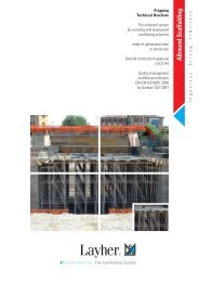
} 13. COMPONENTS OF THE SYSTEM<br />
1<br />
2<br />
3<br />
4<br />
5<br />
1259.200 Castor 700<br />
with spindle and lock<br />
Steel. Plastic wheel, dia. 200 mm.<br />
Permissible load-bearing capacity 7 kN<br />
( 700 kg). With double brake lever and<br />
load centering in the braked state. Wheel<br />
and slewing ring can be locked. Adjustment<br />
range 0.3 – 0.6 m, weight 7.7 kg.<br />
1260.200 Castor 1000<br />
with spindle and lock<br />
Steel. Plastic wheel, dia. 200 mm.<br />
Permissible load-bearing capacity 10 kN<br />
( 1000 kg). With double brake lever and<br />
load centering in the braked state. Wheel<br />
and slewing ring can be locked. Adjustment<br />
range 0.3 – 0.6 m, weight 9.4 kg.<br />
1268.200 Castor 1000 with<br />
spindle and lock<br />
Aluminium rim with Vulkollan tyre, dia.<br />
200 mm. Permissible load-bearing capacity<br />
10 kN ( 1000 kg). Special wheel for<br />
sensitive floor surfaces. Wheel and<br />
slewing ring can be locked. Adjustment<br />
range 0.3 – 0.6 m, weight 10.0 kg.<br />
1323.180 Mobile beam with bar, 1.8 m<br />
Steel rectangular tube, hot-dip-<br />
galvanized. For widening the base of<br />
towers with up to 6.6 m platform<br />
height. Width 1.8 m, weight 16.8 kg.<br />
1323.320 Mobile beam<br />
with bar, 3.2 m, adjustable<br />
Steel rectangular tube, hot-dip-galvanized.<br />
For widening the base of towers with up<br />
to 11.6 m platform height. Width<br />
max. 3.2 m, min. 2.3 m, weight 42.5 kg.<br />
6<br />
7<br />
8<br />
9<br />
10<br />
11<br />
1338.320 Mobile beam<br />
with 2 spigots, 3.2 m, adjustable<br />
Steel rectangular tube, hot-dip-<br />
galvanized. For base widening in<br />
special rolling tower structures. Width<br />
max. 3.2 m, min. 2.3 m, weight 42.6 kg.<br />
1211.285<br />
Basic tube 2.85 m<br />
Steel tube, hot-dip-galvanized.<br />
Length 2.85 m, weight 12.2 kg.<br />
1324.285<br />
Basic strut 2.85 m<br />
with 2 half-couplers, steel tube<br />
hot-dip-galvanized,<br />
length 2.85 m, weight 9.3 kg.<br />
1344.002<br />
Access ledger 0.3<br />
Aluminium,<br />
length 0.27 m,<br />
weight 2.9 kg.<br />
1249.000<br />
Ballast (10 kg)<br />
Steel, hot-dip-galvanized<br />
with half-coupler.<br />
1337.000<br />
Spigot, adjustable<br />
for twin towers, steel, hot-dip-<br />
galvanized. For use with mobile<br />
beam No. 1338.320.<br />
Weight 2.1 kg.<br />
27
12<br />
13<br />
14<br />
15<br />
16<br />
28<br />
1297.004 Ladder frame 75/4<br />
Aluminium, with press-in spigot.<br />
Rungs with non-slip grooving.<br />
Height 1.0 m, width 0.75 m,<br />
weight 4.7 kg.<br />
1298.004 Ladder frame 75/4<br />
Aluminium, with screw-in spigot.<br />
1297.008 Ladder frame 75/8<br />
Aluminium, with press-in spigot.<br />
Rungs with non-slip grooving.<br />
Height 2.0 m, width 0.75 m,<br />
weight 8.6 kg.<br />
1298.008 Ladder frame 75/8<br />
Aluminium, with screw-in spigot.<br />
1250.000 Spring clip<br />
Steel.<br />
Weight 0.1 kg.<br />
1205.285 Rear guardrail 2.85 m<br />
Aluminium.<br />
Length 2.85 m,<br />
weight 3.6 kg.<br />
1206.285<br />
Double guardrail 2.85 m<br />
Aluminium.<br />
Length 2.85 m, height 0.5 m,<br />
weight 8.0 kg.<br />
17<br />
18<br />
19<br />
20<br />
21<br />
22<br />
23<br />
1207.285 Beam 2.85 m<br />
Aluminium. Support elements in<br />
tower construction kit or double<br />
side protection.<br />
Length 2.85 m, height 0.5 m,<br />
weight 9.6 kg.<br />
1208.285 Diagonal brace 3.35 m<br />
Aluminium.<br />
Length 3.35 m,<br />
weight 4.1 kg.<br />
1208.295 Diagonal brace 2.95 m<br />
Aluminium.<br />
Length 2.95 m,<br />
weight 3.8 kg.<br />
1347.335<br />
Deck diagonal brace 3.35 m<br />
Weight 5.0 kg.<br />
1275.110 <strong>Uni</strong> distance tube<br />
Aluminium tube with hook and<br />
rubber foot. Dia. 48.3 mm,<br />
length 1.1 m, weight 1.4 kg.<br />
1269.019/1269.022<br />
Special tower screw coupler,<br />
rigid<br />
WS 19 or 22 mm, weight 1.1 kg.<br />
1242.285 Access deck 2.85 m<br />
Aluminium frame, with plywood<br />
deck and hatch (BFU 100 G) with<br />
phenolic resin coating.<br />
Length 2.85 m, width 0.68 m,<br />
weight 21.6 kg.
24<br />
25<br />
26<br />
27<br />
28<br />
29<br />
1241.285 Deck 2.85 m<br />
Aluminium frame, with plywood<br />
deck (BFU 100G) with phenolic<br />
resin coating.<br />
Length 2.85 m, width 0.68 m,<br />
weight 20.0 kg.<br />
1300.001<br />
<strong>Uni</strong> assembly hook<br />
Polyethylene, set of 2.<br />
Weight 1.2 kg.<br />
1341.075<br />
Bracket 0.75 m<br />
for rolling towers, aluminium.<br />
For widening of the work platform<br />
on one or two sides.<br />
Width 0.75 m, height 0.9 m,<br />
weight 5.4 kg.<br />
1339.285<br />
Intermediate deck 2.85 m<br />
Aluminium. For console bracket<br />
structures. Length 2.85 m,<br />
width 0.23 m, weight 10.5 kg.<br />
1239.285<br />
Toe board 2.85 m, with claw<br />
Wood.<br />
Length 2.86 m, height 0.15 m,<br />
weight 5.6 kg.<br />
1238.075<br />
End toe board 0.75 m<br />
Wood.<br />
Length 0.73 m, height 0.15 m,<br />
weight 1.6 kg.<br />
30<br />
31<br />
32<br />
33<br />
34<br />
35<br />
Identification and Approval Inspection Record<br />
of mobile working platforms (rolling towers) as per DIN EN 1004<br />
as per Sections 10 and 11 of the German Ordinance on Industrial Safety and Health (BetrSichV)<br />
Scaffolding erector:<br />
Qualified person during assembly:<br />
Assembly period:<br />
Tower No.: ____________________________<br />
Qualified person for inspection:<br />
Telephone number:<br />
Inspection period:<br />
Yes No<br />
Place of erection:<br />
Tower No.:<br />
Scaffolding group: � 2 (150 kg/m²) � 3 (200 kg/m²)<br />
Ladder Frames paired ladders with double bracing � �<br />
The sum of the live loads of all scaffolding levels positioned one above the other inside one scaffolding bay<br />
horizontal bracing in the basic structure � �<br />
must not exceed the above value.<br />
standard joints secured (spring clip) � �<br />
Access type: � A Stairway � B Step Ladder � C Angled Ladder � D Vertical Ladder<br />
Decks decks / hatches in suitable number / spacing � �<br />
Maximum permissible platform height as per instructions for assembly and use.<br />
Accesses stairway, step ladder, angled ladder or vertical � �<br />
ladder provided<br />
outside buildings: ________________ m<br />
inside buildings: ________________ m<br />
Side protection 3-part side protection fitted at all working levels � �<br />
Restrictions on use applying to the user:<br />
Ballast ballasting as per instructions for assembly and use � �<br />
Widening suitable for height � �<br />
Special structures According to Instructions for Assembly and Use / Static � �<br />
Unauthorized changes to the scaffolding are prohibited unless the scaffolding erector<br />
has been consulted beforehand! The castors must be locked during work on the scaffolding.<br />
The instructions for assembly and use must be carefully complied with!<br />
Notes and comments:<br />
Inspected and approved<br />
Qualified person of scaffolding erector:<br />
Date, signature<br />
Wilhelm <strong>Layher</strong> GmbH & Co. KG<br />
Scaffolding Grandstands Ladders<br />
Ochsenbacher Strasse 56<br />
D-74363 Gueglingen-Eibensbach<br />
Client:<br />
Telephone number:<br />
Qualified person of user:<br />
Date, signature<br />
Scaffolding components no visible damaged � �<br />
Castors load bearing capacity suitable � �<br />
provided with locking brake / � �<br />
secured by locking screw against breaking loose � �<br />
Inspected and approved<br />
Qualified person of scaffolding erector:<br />
Date, signature<br />
Qualified person of user:<br />
Date, signature<br />
1248.260<br />
Stabilizer, extendable<br />
Aluminium.<br />
Length 2.6 m,<br />
weight 8.5 kg.<br />
1248.500 Stabilizer, 5 m<br />
Aluminium.<br />
Length 5.0 m,<br />
weight 14.9 kg.<br />
1248.261 Rotation lock<br />
Aluminium.<br />
Length 0.5 m,<br />
weight 2.8 kg.<br />
1314.008 Suspended ladder<br />
8 rungs,<br />
weight 5.8 kg.<br />
6344.200 Prohibition sign<br />
Identification sign<br />
for rolling towers.<br />
Orderable only in German.<br />
29
} 14. CERTIFICATE<br />
30
} 15. IDENTIFICATION SIGN<br />
Identification and Approval Inspection Recor<br />
of mobile working platforms (rolling towers) as per DIN EN 1004<br />
as per Sections 10 and 11 of the German Ordinance on Industrial<br />
Scaffolding erector:<br />
Telephone number:<br />
Place of erection:<br />
Tower No.:<br />
Scaffolding group:<br />
Access type:<br />
outside buildings: ________________ m<br />
inside buildings: ________________ m<br />
Restrictions on use applying to the user:<br />
Inspected and approved<br />
Qualified person of scaffolding erector:<br />
Date, signature<br />
Qualified person during assembly:<br />
Assembly period:<br />
Qualified person for inspection:<br />
Inspection period:<br />
Client:<br />
Telephone number:<br />
� 2 (150 kg/m²) � 3 (200 kg/m²)<br />
The sum of the live loads of all scaffolding levels positioned one above the other inside one scaffolding bay<br />
must not exceed the above value.<br />
� A Stairway � B Step Ladder � C Angled Ladder � D Vertical Ladder<br />
Maximum permissible platform height as per instructions for assembly and use.<br />
Unauthorized changes to the scaffolding are prohibited unless the scaffolding erector<br />
has been consulted beforehand! The castors must be locked during work on the scaffolding.<br />
The instructions for assembly and use must be carefully complied with!<br />
Wilhelm <strong>Layher</strong> GmbH & Co. KG<br />
Scaffolding Grandstands Ladders<br />
Ochsenbacher Strasse 56<br />
D-74363 Gueglingen-Eibensbach<br />
Qualified person of user:<br />
Date, signature<br />
Tower No.: ____________________________<br />
Scaffolding components no visible damaged<br />
Castors load bearing capacity suitable<br />
provided with locking brake /<br />
secured by locking screw against breaking<br />
Ladder Frames paired ladders with double bracing<br />
horizontal bracing in the basic structure<br />
standard joints secured (spring clip)<br />
Decks decks / hatches in suitable number / spac<br />
Accesses stairway, step ladder, angled ladder or ve<br />
ladder provided<br />
Side protection 3-part side protection fitted at all working le<br />
Ballast ballasting as per instructions for assembly<br />
Widening suitable for height<br />
Special structures According to Instructions for Assembly an<br />
Notes and comments:<br />
Inspected and approved<br />
Qualified person of scaffolding erector:<br />
MASTER COPY<br />
Date, signature<br />
The identification sign incl. inspection record can be<br />
downloaded from www.layher.com.<br />
Qualified per<br />
Date, signature<br />
31
Wilhelm <strong>Layher</strong> GmbH & Co. KG<br />
Scaffolding Grandstands Ladders<br />
Post Box 40<br />
D-74361 Gueglingen-Eibensbach<br />
Phone +49 71 35 70-0<br />
Fax +49 71 35 70-3 72<br />
E-Mail export@layher.com<br />
www.layher.com<br />
Edition 01.08.2012 Ref. No. 8107.260