Machine Vision Introduction (6.5Mb allow 30 secs - Sick
Machine Vision Introduction (6.5Mb allow 30 secs - Sick
Machine Vision Introduction (6.5Mb allow 30 secs - Sick

Create successful ePaper yourself
Turn your PDF publications into a flip-book with our unique Google optimized e-Paper software.
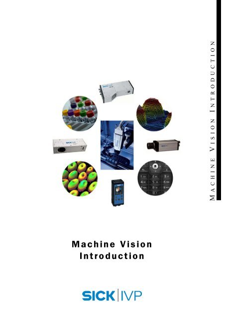
<strong>Machine</strong> <strong>Vision</strong><br />
<strong>Introduction</strong><br />
M ACHINE V ISION I NTRODUCTION
Contents<br />
© SICK IVP<br />
Version 2.2, December 2006<br />
All rights reserved<br />
Subject to change without prior notice<br />
2 SICK IVP • Industrial Sensors • www.sickivp.com • All rights reserved<br />
<strong>Machine</strong> <strong>Vision</strong> <strong>Introduction</strong>
<strong>Machine</strong> <strong>Vision</strong> <strong>Introduction</strong><br />
Contents<br />
Contents<br />
1 <strong>Introduction</strong>............................................................................................................................................................7<br />
1.1 Objective ......................................................................................................................................7<br />
1.2 Application Types ........................................................................................................................8<br />
1.2.1 Locate.............................................................................................................................8<br />
1.2.2 Measure .........................................................................................................................8<br />
1.2.3 Inspect............................................................................................................................8<br />
1.2.4 Identify............................................................................................................................8<br />
1.3 Branch Types ...............................................................................................................................9<br />
1.4 Camera Types..............................................................................................................................9<br />
1.4.1 <strong>Vision</strong> Sensors ...............................................................................................................9<br />
1.4.2 Smart Cameras........................................................................................................... 10<br />
1.4.3 PC-based Systems...................................................................................................... 11<br />
2 Imaging................................................................................................................................................................. 12<br />
2.1 Basic Camera Concepts...........................................................................................................12<br />
2.1.1 Digital Imaging............................................................................................................ 12<br />
2.1.2 Lenses and Focal Length........................................................................................... 13<br />
2.1.3 Field of View in 2D...................................................................................................... 14<br />
2.1.4 Aperture and F-stop.................................................................................................... 14<br />
2.1.5 Depth of Field ............................................................................................................. 15<br />
2.2 Basic Image Concepts ............................................................................................................. 16<br />
2.2.1 Pixels and Resolution................................................................................................. 16<br />
2.2.2 Intensity.......................................................................................................................17<br />
2.2.3 Exposure ..................................................................................................................... 18<br />
2.2.4 Gain ............................................................................................................................. 19<br />
2.2.5 Contrast and Histogram............................................................................................. 19<br />
3 Illumination.......................................................................................................................................................... 21<br />
3.1 Illumination Principles ............................................................................................................. 21<br />
3.1.1 Light and Color ........................................................................................................... 21<br />
3.1.2 Reflection, Absorption, and Transmission ............................................................... 22<br />
3.2 Lighting Types........................................................................................................................... 23<br />
3.2.1 Ring Light .................................................................................................................... 23<br />
3.2.2 Spot Light.................................................................................................................... 23<br />
3.2.3 Backlight ..................................................................................................................... 24<br />
3.2.4 Darkfield...................................................................................................................... 24<br />
3.2.5 On-Axis Light ............................................................................................................... 25<br />
3.2.6 Dome Light.................................................................................................................. 26<br />
3.2.7 Laser Line ................................................................................................................... 26<br />
3.3 Lighting Variants and Accessories.......................................................................................... 27<br />
3.3.1 Strobe or Constant Light............................................................................................ 27<br />
3.3.2 Diffusor Plate.............................................................................................................. 27<br />
3.3.3 LED Color .................................................................................................................... 27<br />
3.3.4 Optical Filters.............................................................................................................. 28<br />
3.4 Safety and Eye Protection .......................................................................................................29<br />
3.4.1 Laser Safety................................................................................................................ 29<br />
3.4.2 LEDs ............................................................................................................................<strong>30</strong><br />
3.4.3 Protective Eyewear..................................................................................................... <strong>30</strong><br />
4 Laser Triangulation ........................................................................................................................................... 31<br />
4.1 Field of View in 3D.................................................................................................................... 31<br />
SICK IVP • Industrial Sensors • www.sickivp.com • All rights reserved 3
Contents<br />
4 SICK IVP • Industrial Sensors • www.sickivp.com • All rights reserved<br />
<strong>Machine</strong> <strong>Vision</strong> <strong>Introduction</strong><br />
4.2 3D Image and Coordinate System.......................................................................................... 32<br />
4.3 Scanning Speed........................................................................................................................ 32<br />
4.4 Occlusion and Missing Data.................................................................................................... 33<br />
4.5 System Components ................................................................................................................ 34<br />
4.6 Ambient Light Robustness....................................................................................................... 34<br />
5 Processing and Analysis..................................................................................................................................35<br />
5.1 Region of Interest..................................................................................................................... 35<br />
5.2 Pixel Counting ........................................................................................................................... 35<br />
5.3 Digital Filters and Operators.................................................................................................... 36<br />
5.4 Thresholds................................................................................................................................. 37<br />
5.5 Edge Finding ............................................................................................................................. 38<br />
5.6 Blob Analysis............................................................................................................................. 38<br />
5.7 Pattern Matching...................................................................................................................... 39<br />
5.8 Coordinate Transformation and Calibration .......................................................................... 39<br />
5.9 Code Reading ........................................................................................................................... 40<br />
5.9.1 Barcode ....................................................................................................................... 40<br />
5.9.2 Matrix Code................................................................................................................. 40<br />
5.10 Text Verification and Reading ................................................................................................. 40<br />
5.10.1 Optical Character Verification: OCV .......................................................................... 40<br />
5.10.2 Optical Character Recognition: OCR ......................................................................... 41<br />
5.11 Cycle Time ................................................................................................................................. 42<br />
5.12 Camera Programming..............................................................................................................42<br />
6 Communication...................................................................................................................................................44<br />
6.1 Digital I/O .................................................................................................................................. 44<br />
6.2 Serial Communication.............................................................................................................. 44<br />
6.3 Protocols ................................................................................................................................... 44<br />
6.4 Networks ................................................................................................................................... 45<br />
6.4.1 Ethernet....................................................................................................................... 45<br />
6.4.2 LAN and WAN.............................................................................................................. 45<br />
7 <strong>Vision</strong> Solution Principles................................................................................................................................46<br />
7.1 Standard Sensors..................................................................................................................... 46<br />
7.2 <strong>Vision</strong> Qualifier.......................................................................................................................... 46<br />
7.2.1 Investment Incentive.................................................................................................. 46<br />
7.2.2 Application Solvability ................................................................................................ 46<br />
7.3 <strong>Vision</strong> Project Parts .................................................................................................................. 47<br />
7.3.1 Feasibility Study.......................................................................................................... 47<br />
7.3.2 Investment .................................................................................................................. 47<br />
7.3.3 Implementation .......................................................................................................... 47<br />
7.3.4 Commissioning and Acceptance Testing ................................................................. 47<br />
7.4 Application Solving Method..................................................................................................... 48<br />
7.4.1 Defining the Task ....................................................................................................... 48<br />
7.4.2 Choosing Hardware.................................................................................................... 48<br />
7.4.3 Choosing Image Processing Tools ............................................................................ 48<br />
7.4.4 Defining a Result Output ........................................................................................... 48<br />
7.4.5 Testing the Application .............................................................................................. 48<br />
7.5 Challenges ................................................................................................................................ 49<br />
7.5.1 Defining Requirements.............................................................................................. 49<br />
7.5.2 Performance ............................................................................................................... 49<br />
7.5.3 System Flexibility ........................................................................................................ 49<br />
7.5.4 Object Presentation Repeatability ............................................................................ 49<br />
7.5.5 Mechanics and Environment..................................................................................... 49
<strong>Machine</strong> <strong>Vision</strong> <strong>Introduction</strong><br />
Contents<br />
8 Appendix .............................................................................................................................................................. 50<br />
A Lens Selection .......................................................................................................................... 50<br />
B Lighting Selection..................................................................................................................... 52<br />
C Resolution, Repeatability, and Accuracy................................................................................ 53<br />
D Motion Blur Calculation ........................................................................................................... 54<br />
E IP Classification ........................................................................................................................ 54<br />
F Ethernet LAN Communication................................................................................................. 55<br />
SICK IVP • Industrial Sensors • www.sickivp.com • All rights reserved 5
<strong>Introduction</strong><br />
Chapter 1 <strong>Machine</strong> <strong>Vision</strong> <strong>Introduction</strong><br />
6 SICK IVP • Industrial Sensors • www.sickivp.com • All rights reserved
<strong>Machine</strong> <strong>Vision</strong> <strong>Introduction</strong> Chapter 1<br />
1 <strong>Introduction</strong><br />
<strong>Introduction</strong><br />
<strong>Machine</strong> vision is the technology to replace or complement manual inspections and<br />
measurements with digital cameras and image processing. The technology is used in a<br />
variety of different industries to automate the production, increase production speed and<br />
yield, and to improve product quality.<br />
<strong>Machine</strong> vision in operation can be described by a four-step flow:<br />
1. Imaging: Take an image.<br />
2. Processing and analysis: Analyze the image to obtain a result.<br />
3. Communication: Send the result to the system in control of the process.<br />
4. Action: Take action depending on the vision system's result.<br />
Wait for new object<br />
1. Take image<br />
4. Take action 2. Analyze image<br />
3. Send result<br />
This introductory text covers basic theoretical topics that are useful in the practical work<br />
with machine vision, either if your profession is in sales or in engineering. The level is set<br />
for the beginner and no special knowledge is required, however a general technical orientation<br />
is essential. The contents are chosen with SICK IVP's cameras in mind, but focus is<br />
on understanding terminology and concepts rather than specific products.<br />
The contents are divided into eight chapters:<br />
1. <strong>Introduction</strong> (this chapter)<br />
2. Imaging<br />
3. Illumination<br />
4. Laser Triangulation<br />
5. Processing and Analysis<br />
6. Communication<br />
7. <strong>Vision</strong> Solution Principles<br />
8. Appendix<br />
The appendix contains some useful but more technical issues needed for a deeper understanding<br />
of the subject.<br />
1.1 Objective<br />
The objective is that you, after reading this document:<br />
1. Understand basic machine vision terminology.<br />
2. Are aware of some possibilities and limitations of machine vision.<br />
3. Have enough theoretical understanding to begin practical work with machine vision.<br />
SICK IVP • Industrial Sensors • www.sickivp.com • All rights reserved 7
<strong>Introduction</strong><br />
Chapter 1 <strong>Machine</strong> <strong>Vision</strong> <strong>Introduction</strong><br />
1.2 Application Types<br />
<strong>Machine</strong> vision applications can be divided into four types from a technical point of view:<br />
Locate, measure, inspect, and identify.<br />
1.2.1 Locate<br />
In locating applications, the purpose of<br />
the vision system is to find the object and<br />
report its position and orientation.<br />
In robot bin picking applications the<br />
camera finds a reference coordinate on<br />
the object, for example center of gravity or<br />
a corner, and then sends the information<br />
to a robot which picks up the object.<br />
1.2.2 Measure<br />
In measurement applications the purpose<br />
of the vision system is to measure physical<br />
dimensions of the object. Examples of<br />
physical dimensions are distance, diameter,<br />
curvature, area, height, and volume.<br />
In the example to the right, a camera<br />
measures multiple diameters of a bottleneck.<br />
1.2.3 Inspect<br />
In inspection applications the purpose of<br />
the vision system is to validate certain<br />
features, for example presence or absence<br />
of a correct label on a bottle,<br />
screws in an assembly, chocolates in a<br />
box, or defects.<br />
In the example to the right, a camera<br />
inspects brake pads for defects.<br />
1.2.4 Identify<br />
In an identification application the vision<br />
system reads various codes and alphanumeric<br />
characters (text and numbers).<br />
In the example to the right, a camera<br />
reads the best before date on a food<br />
package.<br />
Examples of codes that can be read<br />
simultaneously on the same package are<br />
barcodes and matrix codes.<br />
8 SICK IVP • Industrial Sensors • www.sickivp.com • All rights reserved
<strong>Introduction</strong><br />
<strong>Machine</strong> <strong>Vision</strong> <strong>Introduction</strong> Chapter 1<br />
1.3 Branch Types<br />
<strong>Machine</strong> vision applications can also be categorized according to branch type, for example:<br />
• Automotive<br />
• Electronics<br />
• Food<br />
• Logistics<br />
• Manufacturing<br />
• Robotics<br />
• Packaging<br />
• Pharmaceutical<br />
• Steel and mining<br />
• Wood.<br />
The branch categories often overlap, for example when a vision-guided robot (robotics) is<br />
used to improve the quality in car production (automotive).<br />
1.4 Camera Types<br />
Cameras used for machine vision are categorized into vision sensors, smart cameras, and<br />
PC-based systems. All camera types are digital, as opposed to analog cameras in traditional<br />
photography. <strong>Vision</strong> sensors and smart cameras analyze the image and produce a<br />
result by themselves, whereas a PC-based system needs an external computer to produce<br />
a result.<br />
1.4.1 <strong>Vision</strong> Sensors<br />
A vision sensor is a specialized vision system that is<br />
configured to perform a specific task, unlike general<br />
camera systems that have more flexible configuration<br />
software.<br />
Thanks to the specific functionality of the vision<br />
sensor, the setup time is short relative to other vision<br />
systems.<br />
Example<br />
The CVS product range includes vision sensors for<br />
color sorting, contour verification, and text reading<br />
functionality.<br />
For example, the vision sensors are used to inspect<br />
lid color on food packages and to verify best before<br />
dates on bottles.<br />
Lid color verification on food packages.<br />
Best before date inspection on bottles.<br />
SICK IVP • Industrial Sensors • www.sickivp.com • All rights reserved 9
<strong>Introduction</strong><br />
Chapter 1 <strong>Machine</strong> <strong>Vision</strong> <strong>Introduction</strong><br />
1.4.2 Smart Cameras<br />
A smart camera is a camera with a built-in image analysis unit that <strong>allow</strong>s the camera to<br />
operate stand alone without a PC. The flexible built-in image analysis functionality provides<br />
inspection possibilities in a vast range of applications.<br />
Smart cameras are very common in 2D machine vision. SICK IVP also produces a smart<br />
camera for 3D analysis.<br />
Example: 2D Smart<br />
The IVC-2D (Industrial <strong>Vision</strong> Camera) is a<br />
stand-alone vision system for 2D analysis.<br />
For example, the system can detect the<br />
correct label and its position on a whisky<br />
cap. A faulty pattern or a misalignment is<br />
reported as a fail.<br />
Measurement of ceramic part dimensions.<br />
Example: 3D Smart<br />
The IVC-3D is a stand-alone vision system<br />
for 3D analysis. It scans calibrated 3D data<br />
in mm, analyzes the image, and outputs<br />
the result.<br />
For example, the system can detect surface<br />
defects, measure height and volume, and<br />
inspect shape.<br />
Scanned wood surface with defects.<br />
10 SICK IVP • Industrial Sensors • www.sickivp.com • All rights reserved<br />
Misaligned label on the cap.<br />
Brake pad (automotive) with defects.
<strong>Introduction</strong><br />
<strong>Machine</strong> <strong>Vision</strong> <strong>Introduction</strong> Chapter 1<br />
1.4.3 PC-based Systems<br />
In a PC-based system the camera captures the image and transfers it to the PC for processing<br />
and analysis. Because of the large amounts of data that need to be transferred to<br />
the PC, these cameras are also referred to as streaming devices.<br />
Example: 3D Camera<br />
The Ruler collects calibrated 3D-shape data in<br />
mm and sends the image to a PC for analysis.<br />
For example, it detects the presence of apples<br />
in a fruit box and measures log dimensions to<br />
optimize board cutting in sawmills.<br />
Volume measurement and presence<br />
detection of apples in a box.<br />
Log scanning for knot detection and<br />
board cutting optimization.<br />
Example: MultiScan Camera<br />
The Ranger has a unique MultiScan functionality that can perform multiple scans simultaneously<br />
in one camera unit, for example generating a 2D gray scale and a 3D image in one<br />
scan. MultiScan is accomplished by simultaneous line scanning on different parts of the<br />
object, where each part is illuminated in a special way.<br />
Example<br />
The Ranger C55 (MultiScan) scans three different kinds of<br />
images of a CD simultaneously:<br />
1. Gray scale for print verification<br />
2. Gloss for crack detection<br />
3. 3D for shape verification.<br />
Gray scale.<br />
Gloss.<br />
3D.<br />
SICK IVP • Industrial Sensors • www.sickivp.com • All rights reserved 11
Imaging<br />
Chapter 2 <strong>Machine</strong> <strong>Vision</strong> <strong>Introduction</strong><br />
2 Imaging<br />
The term imaging defines the act of creating an image. Imaging has several technical<br />
names: Acquiring, capturing, or grabbing. To grab a high-quality image is the number one<br />
goal for a successful vision application.<br />
This chapter covers the most basic concepts that are essential to understand when learning<br />
how to grab images.<br />
2.1 Basic Camera Concepts<br />
A simplified camera setup consists of camera, lens, lighting, and object. The lighting<br />
illuminates the object and the reflected light is seen by the camera. The object is often<br />
referred to as target.<br />
Camera<br />
Lens<br />
2.1.1 Digital Imaging<br />
In the digital camera, a sensor chip is used to<br />
grab a digital image, instead of using a<br />
photographic film as in traditional photography.<br />
On the sensor there is an array of lightsensitive<br />
pixels. The sensor is also referred<br />
to as imager.<br />
12 SICK IVP • Industrial Sensors • www.sickivp.com • All rights reserved<br />
Lighting<br />
Object/target<br />
Sensor chip with an array of<br />
light-sensitive pixels.<br />
There are two technologies used for digital image sensors:<br />
1. CCD (Charge-Coupled Device)<br />
2. CMOS (Complementary Metal Oxide Semiconductor).<br />
Each type has its technical pros and cons. The difference of the technologies is beyond the<br />
scope of this introductory text.<br />
In PC-based systems, a frame grabber takes the raw image data into a format that is<br />
suitable for the image analysis software.<br />
A line scan camera is a special case of the above where the sensor has only one pixel row.<br />
It captures one line at a time, which can either be analyzed by itself or several lines can be<br />
put together to form a complete image.<br />
Sensor<br />
Lens<br />
Light
Imaging<br />
<strong>Machine</strong> <strong>Vision</strong> <strong>Introduction</strong> Chapter 2<br />
2.1.2 Lenses and Focal Length<br />
The lens focuses the light that enters the camera in<br />
a way that creates a sharp image. Another word for<br />
lens is objective.<br />
An image in focus means that the object edges<br />
appear sharp. If the object is out of focus, the<br />
image becomes blurred. Lenses for photography<br />
often have auto-focus, whereas lenses for machine<br />
vision either have a fixed focus or manually adjustable<br />
focus.<br />
Focused or sharp image.<br />
Unfocused or blurred image.<br />
The main differences between lens types are their angle of view and focal length. The two<br />
terms are essentially different ways of describing the same thing.<br />
The angle of view determines how much of the visual scene the camera sees. A wide<br />
angle lens sees a larger part of the scene, whereas the small angle of view of a tele lens<br />
<strong>allow</strong>s seeing details from longer distances.<br />
Lens<br />
Angle of view<br />
The focal length is the distance between the lens and the focal point. When the focal point<br />
is on the sensor, the image is in focus.<br />
Lens<br />
Sensor<br />
Wide angle<br />
Focal length<br />
Normal<br />
Lens<br />
Parallel light beams<br />
Focal length is related to angle of view in that a long focal length corresponds to a small<br />
angle of view, and vice versa.<br />
Tele<br />
SICK IVP • Industrial Sensors • www.sickivp.com • All rights reserved 13
Imaging<br />
Chapter 2 <strong>Machine</strong> <strong>Vision</strong> <strong>Introduction</strong><br />
Example<br />
Image taken with a wide<br />
angle lens, i.e. having a<br />
small focal length (8mm).<br />
Image taken from the same<br />
distance with a medium<br />
focal length (25 mm)<br />
14 SICK IVP • Industrial Sensors • www.sickivp.com • All rights reserved<br />
Image taken from the same<br />
distance with a long focal<br />
length (50 mm tele).<br />
In addition to the standard lenses there are other types for special purposes, described in<br />
further detail in the Appendix.<br />
2.1.3 Field of View in 2D<br />
The FOV (Field of View) in 2D systems is the full area that a camera sees. The FOV is<br />
specified by its width and height. The object distance is the distance between the lens<br />
and the object.<br />
The object distance is also called LTO (lens-to-object) distance or working distance.<br />
2.1.4 Aperture and F-stop<br />
The aperture is the opening in the lens that controls the amount of light that is let onto the<br />
sensor. In quality lenses, the aperture is adjustable.<br />
Large<br />
aperture<br />
Object distance<br />
Large aperture, much light is let through.<br />
Small aperture, only lets a small<br />
amount of light through.<br />
The size of the aperture is measured by its F-stop value. A large F-stop value means a<br />
small aperture opening, and vice versa. For standard CCTV lenses, the F-stop value is<br />
adjustable in the range between F1.4 and F16.<br />
FOV<br />
Small<br />
aperture
Imaging<br />
<strong>Machine</strong> <strong>Vision</strong> <strong>Introduction</strong> Chapter 2<br />
2.1.5 Depth of Field<br />
The minimum object distance (sometimes abbreviated MOD) is the closest distance in<br />
which the camera lens can focus and maximum object distance is the farthest distance.<br />
Standard lenses have no maximum object distance (infinity), but special types such as<br />
macro lenses do.<br />
The focal plane is found at the distance where the focus is as sharp as possible. Objects<br />
closer or farther away than the focal plane can also be considered to be in focus. This<br />
distance interval where good-enough focus is obtained is called depth of field (DOF).<br />
The depth of field depends on both the focal length and the aperture adjustment (described<br />
in next section). Theoretically, perfect focus is only obtained in the focal plane at<br />
an exact distance from the lens, but for practical purposes the focus is good enough within<br />
the depth of field. Rules of thumb:<br />
1. A long focal length gives a sh<strong>allow</strong> depth of field, and vice versa.<br />
2. A large aperture gives a sh<strong>allow</strong> depth of field, and vice versa.<br />
Example<br />
Small aperture and deep depth of field.<br />
Impossible to focus Possible to focus<br />
Minimum object distance<br />
Impossible to focus<br />
Minimum object distance<br />
Focal plane<br />
Out of<br />
focus<br />
In focus<br />
Depth of<br />
field<br />
Out of<br />
focus<br />
Large aperture and sh<strong>allow</strong> depth of field.<br />
Notice how the far-away text is blurred.<br />
SICK IVP • Industrial Sensors • www.sickivp.com • All rights reserved 15
Imaging<br />
Chapter 2 <strong>Machine</strong> <strong>Vision</strong> <strong>Introduction</strong><br />
By adding a distance ring between the camera and the lens, the focal plane (and thus the<br />
MOD) can be moved closer to the camera. A distance ring is also referred to as shim,<br />
spacer, or extension ring.<br />
A thick distance ring is called an extension tube. It makes it possible to position the<br />
camera very close to the object, also known as macro functionality.<br />
Distance rings and extension tubes are used to decrease the minimum object distance.<br />
The thicker the ring or tube, the smaller the minimum object distance.<br />
A side-effect of using a distance ring is that a maximum object distance is introduced and<br />
that the depth of field range decreases.<br />
Distance ring<br />
1 mm<br />
2.2 Basic Image Concepts<br />
Maximum object distance<br />
Impossible<br />
to focus<br />
Minimum<br />
object<br />
distance<br />
This section treats basic image terminology and concepts that are needed when working<br />
with any vision sensor or system.<br />
2.2.1 Pixels and Resolution<br />
A pixel is the smallest element in a digital image. Normally, the pixel in the image corresponds<br />
directly to the physical pixel on the sensor.<br />
Pixel is an abbreviation of 'picture element'. x<br />
Normally, the pixels are so small that they<br />
Pixel<br />
only become distinguishable from one another<br />
if the image is enlarged.<br />
y<br />
To the right is an example of a very small<br />
image with dimension 8x8 pixels. The dimensions<br />
are called x and y, where x corresponds<br />
to the image columns and y to the rows.<br />
16 SICK IVP • Industrial Sensors • www.sickivp.com • All rights reserved<br />
In<br />
focus<br />
Depth of<br />
field<br />
Impossible to focus
Imaging<br />
<strong>Machine</strong> <strong>Vision</strong> <strong>Introduction</strong> Chapter 2<br />
Typical values of sensor resolution in 2D machine vision are:<br />
1. VGA (Video Graphics Array): 640x480 pixels<br />
2. XGA (Extended Graphics Array): 1024x768 pixels<br />
3. SXGA (Super Extended Graphics Array): 1280x1024 pixels<br />
Note the direction of the y axis, which is opposite from what is taught in school mathematics.<br />
This is explained by the image being treated as a matrix, where the upper-left corner is<br />
the (0,0) element. The purpose of the coordinate system and matrix representation is to<br />
make calculations and programming easier.<br />
The object resolution is the physical dimension on the object that corresponds to one<br />
pixel on the sensor. Common units for object resolution are μm (microns) per pixel and mm<br />
per pixel. In some measurements the resolution can be smaller than a pixel. This is<br />
achieved by interpolation algorithms that extract subpixel information from pixel data.<br />
Example: Object Resolution Calculation<br />
The following practical method gives a good<br />
approximation of the object resolution:<br />
FOV width = 50 mm<br />
Sensor resolution = 640x480 pixels<br />
Calculation of object resolution in x:<br />
50<br />
= = 0.<br />
08 mm / pix<br />
640<br />
Result: The object resolution is 0.08 mm<br />
per pixel in x.<br />
2.2.2 Intensity<br />
The brightness of a pixel is called intensity. The intensity information is stored for each<br />
pixel in the image and can be of different types. Examples:<br />
1. Binary: One bit per pixel.<br />
0<br />
y<br />
2. Gray scale: Typically one byte per pixel.<br />
x<br />
0 255<br />
SICK IVP • Industrial Sensors • www.sickivp.com • All rights reserved 17<br />
1
Imaging<br />
Chapter 2 <strong>Machine</strong> <strong>Vision</strong> <strong>Introduction</strong><br />
3. Color: Typically one byte per pixel and color. Three bytes are needed to obtain full<br />
color information. One pixel thus contains three components (R, G, B).<br />
When the intensity of a pixel is digitized and described by a byte, the information is quantized<br />
into discrete levels. The number of bits per byte is called bit-depth. Most often in<br />
machine vision, 8 bits per pixel are enough. Deeper bit-depths can be used in high-end<br />
sensors and sensitive applications.<br />
Example<br />
Binary image.<br />
Gray scale image.<br />
18 SICK IVP • Industrial Sensors • www.sickivp.com • All rights reserved<br />
Color image.<br />
Because of the different amounts of data needed to store each pixel (e.g. 1, 8, and 24<br />
bits), the image processing time will be longer for color and gray scale than for binary.<br />
2.2.3 Exposure<br />
Exposure is how much light is detected by the photographic film or sensor. The exposure<br />
amount is determined by two factors:<br />
1. Exposure time: Duration of the exposure, measured in milliseconds (ms). Also<br />
called shutter time from traditional photography.<br />
2. Aperture size: Controls the amount of light that passes through the lens.<br />
Thus the total exposure is the combined result of these two parameters.<br />
If the exposure time is too short for the sensor to capture enough light, the image is said to<br />
be underexposed. If there is too much light and the sensor is saturated, the image is said<br />
to be overexposed.<br />
Example<br />
0<br />
0<br />
0<br />
Underexposed image.<br />
Normally exposed image.<br />
255<br />
255<br />
255<br />
Overexposed image with<br />
saturated areas (white).
Imaging<br />
<strong>Machine</strong> <strong>Vision</strong> <strong>Introduction</strong> Chapter 2<br />
A topic related to exposure time is motion blur. If the object is moving and exposure time<br />
is too long, the image will be blurred and application robustness is threatened. In applications<br />
where a short exposure time is necessary because of object speed, there are three<br />
methods to make the image bright enough:<br />
1. Illuminate the object with high-intensity lighting (strobe)<br />
2. Open up the aperture to <strong>allow</strong> more light into the camera<br />
3. Electronic gain (described in next section)<br />
Example<br />
A short exposure time yields<br />
a sharp image.<br />
A long exposure time causes motion blur<br />
if the object is moving fast.<br />
2.2.4 Gain<br />
Exposure time and aperture size are the physical ways to control image intensity. There is<br />
also an electronic way called gain that amplifies the intensity values after the sensor has<br />
already been exposed, very much like the volume control of a radio (which doesn’t actually<br />
make the artist sing louder). The tradeoff of compensating insufficient exposure with a<br />
high gain is amplified noise. A grainy image appears.<br />
Normally exposed image.<br />
Image where underexposure has been<br />
compensated with a high gain.<br />
2.2.5 Contrast and Histogram<br />
Contrast is the relative difference between bright and dark areas in an image. Contrast is<br />
necessary to see anything at all in an image.<br />
Low contrast.<br />
Normal contrast.<br />
High contrast.<br />
SICK IVP • Industrial Sensors • www.sickivp.com • All rights reserved 19
Imaging<br />
Chapter 2 <strong>Machine</strong> <strong>Vision</strong> <strong>Introduction</strong><br />
A histogram is a diagram where the pixels are sorted in order of increasing intensity<br />
values. Below is an example image that only contains six different gray values. All pixels of<br />
a specific intensity in the image (left) become one bar in the histogram (right).<br />
Example image.<br />
→<br />
20 SICK IVP • Industrial Sensors • www.sickivp.com • All rights reserved<br />
Histogram of the example image.<br />
Histograms for color images work the same way as for grayscale, where each color channel<br />
(R, G, B) is represented by its individual histogram.<br />
Typically the gray scale image contains many more gray levels than those present in the<br />
example image above. This gives the histogram a more continuous appearance. The<br />
histogram can now be used to understand the concept of contrast better, as shown in the<br />
example below. Notice how a lower contrast translates into a narrower histogram.<br />
Normal contrast.<br />
Low contrast.<br />
→<br />
→<br />
Number of pixels<br />
0<br />
0<br />
The histogram covers a large part of the gray scale.<br />
Number of pixels<br />
0<br />
0<br />
Number of pixels<br />
0<br />
0<br />
Intensity value 255<br />
Intensity value 255<br />
Intensity value 255<br />
The histogram is compressed.
Illumination<br />
<strong>Machine</strong> <strong>Vision</strong> <strong>Introduction</strong> Chapter 3<br />
3 Illumination<br />
Light is of crucial importance in machine vision. The goal of lighting in machine vision is to<br />
obtain a robust application by:<br />
1. Enhancing the features to be inspected.<br />
2. Assuring high repeatability in image quality.<br />
Illumination is the way an object is lit up and lighting is the actual lamp that generates the<br />
illumination.<br />
Light can be ambient, such as normal indoor light or sunlight, or special light that has<br />
been chosen with the particular vision application's needs in mind.<br />
Most machine vision applications are sensitive to lighting variations, why ambient light<br />
needs to be eliminated by a cover, called shroud.<br />
3.1 Illumination Principles<br />
Using different illumination methods on the same object can yield a wide variety of results.<br />
To enhance the particular features that need to be inspected, it is important to understand<br />
basic illumination principles.<br />
3.1.1 Light and Color<br />
Light can be described as waves with three properties:<br />
1. Wavelength or color, measured in nm (nanometers)<br />
2. Intensity<br />
3. Polarization.<br />
Mainly wavelength and intensity is of importance in machine vision, whereas the polarization<br />
is only considered in special cases.<br />
Different wavelengths correspond to different colors. The human eye can see colors in the<br />
visible spectrum, whose colors range from violet to red. Light with shorter wavelength<br />
than violet is called UV (ultraviolet) and longer wavelength than red is called IR (infrared).<br />
UV<br />
The spectral response of a sensor is the sensitivity curve for different wavelengths. Camera<br />
sensors can have a different spectral response than the human eye.<br />
Example<br />
Visible spectrum IR<br />
400 nm 500 nm 600 nm<br />
700 nm<br />
Spectral response of a gray scale CCD sensor. Maximum sensitivity is for green (500 nm).<br />
SICK IVP • Industrial Sensors • www.sickivp.com • All rights reserved 21
Illumination<br />
Chapter 3 <strong>Machine</strong> <strong>Vision</strong> <strong>Introduction</strong><br />
3.1.2 Reflection, Absorption, and Transmission<br />
The optical axis is a thought line through the center of the lens, i.e. the direction the<br />
camera is looking.<br />
Camera Lens<br />
The camera sees the object thanks to light that is reflected on its surface. In the figure<br />
below, all light is reflected in one direction. This is called direct or specular reflection and<br />
is most prevalent when the object is glossy (mirror-like).<br />
Incident light<br />
Angle of incidence<br />
The angle of incidence and angle of reflection are always equal when measured from the<br />
surface normal.<br />
When the surface is not glossy, i.e. has a matte finish, there is also diffuse reflection.<br />
Light that is not reflected is absorbed in the material.<br />
Transparent or semi-transparent materials also transmit light.<br />
The above principles, reflection, absorption, and transmission, constitute the basis of most<br />
lighting methods in machine vision.<br />
There is a fourth principle, emission, when a material produces light, for example when<br />
molten steel glows red because of its high temperature.<br />
22 SICK IVP • Industrial Sensors • www.sickivp.com • All rights reserved<br />
Optical axis<br />
Reflected light<br />
Incident light Main reflection<br />
Incident light<br />
Semi-transparent<br />
surface<br />
Surface<br />
normal<br />
Glossy surface<br />
Angle of reflection<br />
Diffuse reflection<br />
Absorbed light<br />
Matte surface<br />
Direct reflection<br />
Absorbed light<br />
Transmitted light
Illumination<br />
<strong>Machine</strong> <strong>Vision</strong> <strong>Introduction</strong> Chapter 3<br />
3.2 Lighting Types<br />
There is a large variety of different lighting types that are available for machine vision. The<br />
types listed here represent some of the most commonly used techniques. The most accepted<br />
type for machine vision is the LED (Light-Emitting Diode), thanks to its even light,<br />
long life, and low power consumption.<br />
3.2.1 Ring Light<br />
A ring light is mounted around the optical axis of the lens, either on the camera or somewhere<br />
in between the camera and the object. The angle of incidence depends on the ring<br />
diameter, where the lighting is mounted, and at what angle the LEDs are aimed.<br />
Pros<br />
• Easy to use<br />
• High intensity and short exposure<br />
times possible<br />
Example<br />
Ambient light.<br />
Ring light<br />
Cons<br />
• Direct reflections, called hot spots,<br />
on reflective surfaces<br />
Ring light. The printed matte surface is<br />
evenly illuminated. Hot spots appear on<br />
shiny surfaces (center), one for each of the<br />
12 LEDs of the ring light.<br />
3.2.2 Spot Light<br />
A spot light has all the light emanating from one direction that is different from the optical<br />
axis. For flat objects, only diffuse reflections reach the camera.<br />
Spot light<br />
Mainly direct reflections<br />
reach the camera<br />
Object<br />
Object<br />
Mainly diffuse reflections<br />
reach the camera<br />
SICK IVP • Industrial Sensors • www.sickivp.com • All rights reserved 23
Illumination<br />
Chapter 3 <strong>Machine</strong> <strong>Vision</strong> <strong>Introduction</strong><br />
Pros<br />
• No hot spots<br />
24 SICK IVP • Industrial Sensors • www.sickivp.com • All rights reserved<br />
Cons<br />
• Uneven illumination<br />
• Requires intense light since it is<br />
dependent on diffuse reflections<br />
3.2.3 Backlight<br />
The backlight principle has the object being illuminated from behind to produce a contour<br />
or silhouette. Typically, the backlight is mounted perpendicularly to the optical axis.<br />
Pros<br />
• Very good contrast<br />
• Robust to texture, color, and ambient<br />
light<br />
Example<br />
Ambient light.<br />
Cons<br />
• Dimensions must be larger than<br />
object<br />
Backlight: Enhances contours<br />
by creating a silhouette.<br />
3.2.4 Darkfield<br />
Darkfield means that the object is illuminated at a large angle of incidence. Direct reflections<br />
only occur where there are edges. Light that falls on flat surfaces is reflected away<br />
from the camera.<br />
Darkfield ring<br />
light<br />
Object Backlight<br />
Only direct reflections<br />
on edges are seen by<br />
the camera<br />
Object
Illumination<br />
<strong>Machine</strong> <strong>Vision</strong> <strong>Introduction</strong> Chapter 3<br />
Pros<br />
• Good enhancement of scratches,<br />
protruding edges, and dirt on surfaces<br />
Example<br />
Ambient light.<br />
Cons<br />
• Mainly works on flat surfaces with<br />
small features<br />
• Requires small distance to object<br />
• The object needs to be somewhat<br />
reflective<br />
Darkfield: Enhances relief contours,<br />
i.e. lights up edges.<br />
3.2.5 On-Axis Light<br />
When an object needs to be illuminated parallel to the optical axis, i.e. directly from the<br />
front, a semi-transparent mirror is used to create an on-axial light source. On-axis is also<br />
called coaxial. Since the beams are parallel to the optical axis, direct reflexes appear on<br />
all surfaces parallel to the focal plane.<br />
Pros<br />
• Very even illumination, no hot<br />
spots<br />
• High contrast on materials with different<br />
reflectivity<br />
Example<br />
Semi-transparent<br />
mirror<br />
Inside of a can as seen with ambient light.<br />
Coaxial light<br />
Light source<br />
Object<br />
Cons<br />
• Low intensity requires long exposure<br />
times<br />
• Cleaning of semi-transparent mirror<br />
(beam-splitter) often needed<br />
Inside of the same can as seen with a<br />
coaxial (on-axis) light:<br />
SICK IVP • Industrial Sensors • www.sickivp.com • All rights reserved 25
Illumination<br />
Chapter 3 <strong>Machine</strong> <strong>Vision</strong> <strong>Introduction</strong><br />
3.2.6 Dome Light<br />
Glossy materials can require a very diffuse illumination without hot spots or shadows. The<br />
dome light produces the needed uniform light intensity thanks to LEDs illuminating the<br />
bright, matte inside of the dome walls. The middle of the image becomes darker because<br />
of the hole in the dome through which the camera is looking.<br />
Pros<br />
• Works well on highly reflective materials<br />
• Uniform illumination, except for<br />
the darker middle of the image. No<br />
hot spots<br />
Example<br />
Dome<br />
Ambient light. On top of the key numbers<br />
is a curved, transparent material causing<br />
direct reflections.<br />
26 SICK IVP • Industrial Sensors • www.sickivp.com • All rights reserved<br />
Cons<br />
• Low intensity requires long exposure<br />
times<br />
• Dimensions must be larger than<br />
object<br />
• Dark area in the middle of the image<br />
The direct reflections are eliminated by<br />
the dome light’s even illumination.<br />
3.2.7 Laser Line<br />
Low-contrast and 3D inspections normally require a 3D camera. In simpler cases where<br />
accuracy and speed are not critical, a 2D camera with a laser line can provide a costefficient<br />
solution.<br />
Pros<br />
• Robust against ambient light.<br />
• Allows height measurements (z<br />
parallel to the optical axis).<br />
• Low-cost 3D for simpler applications.<br />
Object<br />
Cons<br />
• Laser safety issues.<br />
• Data along y is lost in favor of z<br />
(height) data.<br />
• Lower accuracy than 3D cameras.
Illumination<br />
<strong>Machine</strong> <strong>Vision</strong> <strong>Introduction</strong> Chapter 3<br />
Example<br />
+ --<br />
Ambient light. Contact lens containers,<br />
the left is facing up (5 mm high at cross)<br />
and the right is facing down (1 mm high at<br />
minus sign).<br />
3.3 Lighting Variants and Accessories<br />
The laser line clearly shows the<br />
height difference.<br />
3.3.1 Strobe or Constant Light<br />
A strobe light is a flashing light. Strobing <strong>allow</strong>s the LED to emit higher light intensity than<br />
what is achieved with a constant light by turbo charging. This means that the LED is<br />
powered with a high current during on-time, after which it is <strong>allow</strong>ed to cool off during the<br />
off-time. The on-time relative to the total cycle time (on-time plus off-time) is referred to as<br />
duty cycle (%).<br />
With higher intensity, the exposure time can be shortened and motion blur reduced. Also,<br />
the life of the lamp is extended.<br />
Strobing a LED lighting requires both software and hardware support.<br />
3.3.2 Diffusor Plate<br />
Many lighting types come in two versions, with or without a diffusor plate. The diffusor<br />
plate converts direct light into diffuse.<br />
The purpose of a diffusor plate is to avoid<br />
bright spots in the image, caused by the direct<br />
light's reflections in glossy surfaces.<br />
Rules of thumb:<br />
1. Glossy objects require diffuse light.<br />
2. Diffusor plates steal light intensity.<br />
Typically, 20-40% of the intensity is lost in the<br />
diffusor plate, which can be an issue in highspeed<br />
applications where short exposure times<br />
are needed.<br />
Two identical white bar lights, with<br />
diffusor plate (top) and without<br />
(bottom).<br />
Diffusor plates work well on multi-LED arrays, whereas single LEDs will still give bright “hot<br />
spots” in the image.<br />
3.3.3 LED Color<br />
LED lightings come in several colors. Most common are red and green. There are also<br />
LEDs in blue, white, UV, and IR. Red LEDs are the cheapest and have up to 10 times longer<br />
life than blue and green LEDs.<br />
SICK IVP • Industrial Sensors • www.sickivp.com • All rights reserved 27
Illumination<br />
Chapter 3 <strong>Machine</strong> <strong>Vision</strong> <strong>Introduction</strong><br />
Ultra-violet (UV)<br />
Not visible to<br />
the eye.<br />
Blue<br />
Green<br />
White, consisting of equal parts<br />
of red, green, and blue.<br />
28 SICK IVP • Industrial Sensors • www.sickivp.com • All rights reserved<br />
Red<br />
Infra-red (IR)<br />
Not visible to<br />
the eye.<br />
Different objects reflect different colors. A blue object appears blue because it reflects the<br />
color blue. Therefore, if blue light is used to illuminate a blue object, it will appear bright in<br />
a gray scale image. If a red light is used to illuminate a blue object it will appear dark. It is<br />
thus possible to use color to an advantage, even in gray scale imaging.<br />
3.3.4 Optical Filters<br />
An optical filter is a layer in front of the sensor or lens that<br />
absorbs certain wavelengths (colors) or polarizations. For example,<br />
sunglasses have an optical filter to protect your eyes from<br />
hazardous UV radiation. Similarly, we can use a filter in front of<br />
the camera to keep the light we want to see and suppress the<br />
rest.<br />
Two main optical filter types are used for machine vision:<br />
1. Band-pass filter: Only transmits light of a certain color, i.e. within a certain wavelength<br />
interval. For example, a red filter only lets red through.<br />
2. Polarization filter: Only transmits light with a certain polarization. Light changes<br />
its polarization when it is reflected, which <strong>allow</strong>s us to filter out unwanted reflections.<br />
Very robust lighting conditions can be achieved by combining an appropriate choice of LED<br />
color with an optical filter having the corresponding band-pass wavelength.<br />
Example<br />
By combining optical filters and selected LED colors, it is possible to improve contrast<br />
between an object of a certain color in the image and its surrounding.<br />
Original image.<br />
Image seen by gray scale camera with<br />
ambient light and without filter.
Illumination<br />
<strong>Machine</strong> <strong>Vision</strong> <strong>Introduction</strong> Chapter 3<br />
Red light and a red band-pass filter.<br />
3.4 Safety and Eye Protection<br />
Green light and a green<br />
band-pass filter.<br />
Light can be harmful if the intensity is too high. Lightings for<br />
vision sometimes reach harmful intensity levels, especially in<br />
techniques where lasers are used but sometimes also for<br />
LEDs. It is important to know the safety classification of the<br />
lighting before using it in practice.<br />
Damage of the eye can be temporary or permanent, depending on the exposure amount.<br />
When the damage is permanent, the light-sensitive cells on the eye's retina have died and<br />
will not grow back. The resulting blindness can be partial or total, depending on how much<br />
of the retina that has been damaged.<br />
3.4.1 Laser Safety<br />
A laser is a light source that emits parallel light beams of one wavelength (color), which<br />
makes the laser light dangerous for the eye.<br />
Lasers are classified into laser classes, ranging from 1 to 4. Classes 2 and 3 are most<br />
common in machine vision. Below is an overview of the classifications.<br />
European<br />
class<br />
American<br />
class<br />
Practical meaning<br />
1-1M I Harmless. Lasers of class 1M may become hazardous<br />
with the use of optics (magnifying glass, telescope, etc).<br />
2-2M II Caution. Not harmful to the eye under normal circumstances.<br />
Blink reflex is fast enough to protect the eye<br />
from permanent damage. Lasers of class 2M may become<br />
hazardous with the use of optics.<br />
3R-3B IIIb Danger. Harmful at direct exposure of the retina or after<br />
reflection on a glossy surface. Usually doesn't produce<br />
harmful diffuse reflections.<br />
4 IV Extreme danger. With hazardous diffuse reflections.<br />
Example<br />
Example of warning label for laser class II/2M.<br />
SICK IVP • Industrial Sensors • www.sickivp.com • All rights reserved 29
Illumination<br />
Chapter 3 <strong>Machine</strong> <strong>Vision</strong> <strong>Introduction</strong><br />
3.4.2 LEDs<br />
LEDs are not lasers from a technical point of view, but they behave similarly in that they<br />
have a small size and emit light in one main direction. Because of this the intensity can be<br />
harmful and a safety classification is needed. There is no system for classifying LEDs<br />
specifically, so the laser classification system has been (temporarily?) adopted for LEDs.<br />
LEDs are often used in strobe lights, which can cause epileptic seizures at certain frequencies<br />
in people with epilepsy.<br />
3.4.3 Protective Eyewear<br />
Protective eyewear is necessary whenever working with<br />
dangerous light. Their purpose is to absorb enough light so<br />
that the intensity becomes harmless to the eye. Three<br />
aspects are important when choosing safety goggles:<br />
1. Which wavelength is emitted by the laser/LED?<br />
2. Which wavelengths are absorbed by the goggles?<br />
3. How much of the light intensity is absorbed?<br />
<strong>30</strong> SICK IVP • Industrial Sensors • www.sickivp.com • All rights reserved
<strong>Machine</strong> <strong>Vision</strong> <strong>Introduction</strong> Chapter 4<br />
4 Laser Triangulation<br />
Laser Triangulation<br />
Laser triangulation is a technique for acquiring 3D height data by illuminating the object<br />
with a laser from one direction and having the camera look from another. The laser beam<br />
is divided into a laser line by a prism. The view angle makes the camera see a height<br />
profile that corresponds to the object's cross-section.<br />
Camera<br />
A laser line is projected onto the object so that a height profile can be seen by a camera<br />
from the side. The height profile corresponds to the cross-section of the object.<br />
The method to grab a complete 3D image is to move the object under the laser line and<br />
put together many consecutive profiles.<br />
4.1 Field of View in 3D<br />
The selected FOV (Field of View) is the rectangular area in which the camera sees the<br />
object's cross-section. The selected FOV, also called defining rectangle, lies within the<br />
trapezoid-shaped maximum FOV.<br />
There are several possible camera/laser geometries in laser triangulation. In the basic<br />
geometry, the distance between the camera unit and the top of the FOV is called stand-off.<br />
The possible width of the FOV is determined by the focal length of the lens, the laser<br />
prism's fan angle, and the stand-off.<br />
Camera<br />
Optical axis<br />
Laser line<br />
Laser<br />
Prism<br />
Laser<br />
View angle<br />
Min stand-off<br />
Max height<br />
range<br />
→<br />
Height profile of<br />
object cross-section<br />
Max<br />
FOV<br />
Fan<br />
angle<br />
Min width<br />
Selected FOV<br />
Max FOV width<br />
The fan angle of the laser line gives the maximum FOV a trapezoidal shape. Within this,<br />
the selected FOV defines the cross-section where the camera is looking at the moment.<br />
SICK IVP • Industrial Sensors • www.sickivp.com • All rights reserved 31<br />
Stand-off
Laser Triangulation<br />
Chapter 4 <strong>Machine</strong> <strong>Vision</strong> <strong>Introduction</strong><br />
4.2 3D Image and Coordinate System<br />
There are a number of different representations of 3D data. SICK IVP uses intensity-coded<br />
height data, where bright is high and dark is low. This can be transformed into a 3D visualization<br />
with color-coded height data.<br />
O x<br />
z<br />
y<br />
3D image with intensity-<br />
coded height data.<br />
32 SICK IVP • Industrial Sensors • www.sickivp.com • All rights reserved<br />
3D image visualized in 3D viewer<br />
with color-coded height data.<br />
The coordinate system in the 3D image is the same as that of a normal 2D image regarding<br />
x and y, with the addition that y now corresponds to time. The additional height dimension<br />
is referred to as the z axis or the range axis.<br />
Since the front of the object becomes the first scanned row in the image, the y axis will be<br />
directed opposite to the conveyor movement direction.<br />
4.3 Scanning Speed<br />
Since laser triangulation is a line scanning method, where the image is grabbed little by<br />
little, it is important that the object moves in a controlled way during the scan.<br />
This can be achieved by either:<br />
1. An encoder that gives a signal each time<br />
the conveyor has moved a certain distance.<br />
2. A constant conveyor speed.<br />
When an encoder is used, it controls the profile<br />
triggering so that the profiles become equidistant.<br />
A constant conveyor speed can often not be guaranteed,<br />
why an encoder is generally recommended.<br />
Encoder.<br />
It is important to note that there is a maximum speed at which the profile grabbing can be<br />
done, determined by the maximum profile rate (profiles/second).<br />
If this speed or maximum profile rate is exceeded, some profiles will be lost and the image<br />
will be distorted despite the use of an encoder. A distorted image means that the object<br />
proportions are wrong. An image can also appear distorted if the x and y resolution are<br />
different (i.e. non-square pixels), which can be desirable when optimizing the resolution.<br />
3D image of a circular object. The proportions<br />
are correct thanks to the use of<br />
an encoder.<br />
A distorted 3D image of the same object.<br />
The proportions are incorrect despite the<br />
use of an encoder, because the scanning<br />
speed has exceeded the maximum<br />
<strong>allow</strong>ed profile rate.
Laser Triangulation<br />
<strong>Machine</strong> <strong>Vision</strong> <strong>Introduction</strong> Chapter 4<br />
The maximum profile rate is limited by three main factors:<br />
1. The exposure of the sensor. A longer exposure time per profile reduces the maximum<br />
profile rate.<br />
2. The sensor read-out time. The time it takes to convert the sensor information to a<br />
digital format.<br />
3. The data transfer rate. The time it takes to transfer 3D data from the camera to<br />
the signal processing unit.<br />
To ensure that the object is scanned in its entirety, it is common to use a photo switch to<br />
start the acquisition at the correct moment. The photo switch is thus used for image<br />
triggering.<br />
In some applications where there is a more continuous flow on the conveyor, it is not<br />
meaningful to trig the scanning by a photo switch. Instead, the camera is used in freerunning<br />
mode, which means that the acquisition of a new image starts as soon as the<br />
previous image is completed. Sometimes it is necessary to have overlapping images to<br />
ensure that everything on the conveyor is fully scanned and analyzed.<br />
4.4 Occlusion and Missing Data<br />
Because of the view angle<br />
between the camera and the<br />
laser line, the camera will not<br />
be able to see behind object<br />
features. This phenomenon is<br />
called camera occlusion (shadowing)<br />
and results in missing<br />
data in the image.<br />
As a consequence, laser triangulation<br />
is not a suitable for<br />
scanning parts of an object<br />
located behind high features.<br />
Examples are inspections of the<br />
bottom of a hole or behind<br />
steep edges.<br />
Because of the fan angle of the<br />
laser, the laser line itself can be<br />
occluded and result in missing<br />
data. This phenomenon is<br />
called laser occlusion.<br />
Camera occlusion occurs behind features<br />
as seen from the camera’s perspective.<br />
Laser occlusion occurs behind features<br />
as seen from the laser’s perspective.<br />
The image below of a roll of scotch tape shows both camera and laser occlusion. The<br />
yellow lines show where the camera occlusion starts to dominate over the laser occlusion.<br />
Laser occlusion<br />
Camera<br />
occlusion<br />
Laser occlusion<br />
Intensity-coded 3D image of a roll of scotch tape,<br />
showing both camera and laser occlusion.<br />
Laser<br />
Laser occlusion<br />
Camera occlusion<br />
SICK IVP • Industrial Sensors • www.sickivp.com • All rights reserved 33
Laser Triangulation<br />
Chapter 4 <strong>Machine</strong> <strong>Vision</strong> <strong>Introduction</strong><br />
4.5 System Components<br />
A typical laser triangulation setup consists of the following components:<br />
1. A laser to produce the height profile.<br />
2. A camera to scan profiles.<br />
3. A conveyor to move the object under the camera.<br />
4. A photo switch to enable the camera when an object is present.<br />
5. An encoder to ensure that the profiles are grabbed at a constant distance, independent<br />
of conveyor speed (up to its maximum <strong>allow</strong>ed value).<br />
6. An image processing unit, either built-in (smart camera) or external (PC), to collect<br />
profiles into an image and to analyze the result.<br />
Conveyor<br />
Cable to PC<br />
Camera<br />
Camera<br />
enable, e.g.<br />
photo switch<br />
In some laser triangulation products, all of the above components are bought and configured<br />
separately for maximum flexibility. Others are partially assembled, for example with a<br />
fixed geometry (view angle), which makes them more ready to use but less flexible.<br />
Example<br />
1. SICK IVP Ranger: All components are separated.<br />
2. SICK IVP Ruler: Camera and laser are built in to create a fixed geometry.<br />
3. SICK IVP IVC-3D: Camera and laser are built in to create a fixed geometry. In addition<br />
to this, the unit contains both image processing hardware and software for<br />
stand-alone use.<br />
4.6 Ambient Light Robustness<br />
Encoder<br />
pulses<br />
The laser emits monochromatic light, meaning that it only contains one wavelength. By<br />
using a narrow band-pass filter in front of the sensor, other wavelengths in the ambient<br />
light can be suppressed. The result is a system that is rather robust against ambient light.<br />
However, when the ambient light contains wavelengths close to that of the laser, this will<br />
be let through the filter and appear as disturbing reflections in the image. Then the installation<br />
needs to be covered, or shrouded. Typically, problems with reflections occur with<br />
sunlight and “warm” artificial light from spotlights.<br />
34 SICK IVP • Industrial Sensors • www.sickivp.com • All rights reserved<br />
Laser<br />
Laser line<br />
x<br />
3D image<br />
z<br />
y
Processing and Analysis<br />
<strong>Machine</strong> <strong>Vision</strong> <strong>Introduction</strong> Chapter 5<br />
5 Processing and Analysis<br />
After the image has been grabbed, the next step is image analysis. This is where the<br />
desired features are extracted automatically by algorithms and conclusions are drawn. A<br />
feature is the general term for information in an image, for example a dimension or a<br />
pattern. Algorithms are also referred to as tools or functions.<br />
Sometimes the image needs preprocessing before the feature extraction, for example by<br />
using a digital filter to enhance the image.<br />
5.1 Region of Interest<br />
A ROI (Region of Interest) is a selected area of concern within an image. The purpose of<br />
using ROIs is to restrict the area of analysis and to <strong>allow</strong> for different analyses in different<br />
areas of the image. An image can contain any number of ROIs. Another term for ROI is AOI<br />
(Area of Interest).<br />
A common situation is when the object location is not the same from image to image. In<br />
order to still inspect the feature of interest, a dynamic ROI that moves with the object can<br />
be created. The dynamic ROI can also be resized using results from previous analysis.<br />
Examples<br />
One ROI is created to verify the logotype<br />
(blue) and another is created for<br />
barcode reading (green).<br />
5.2 Pixel Counting<br />
A ROI is placed around each pill in the<br />
blister pack and the pass/fail analysis is<br />
performed once per ROI.<br />
Pixel counting is the most basic analysis method. The algorithm finds the number of<br />
pixels within a ROI that have intensities within a certain gray level interval.<br />
Pixel counting is used to measure area and to find deviances from a normal appearance<br />
of an object, for example missing pieces, spots, or cracks.<br />
A pixel counter gives the pixel sum or area as a result.<br />
Example<br />
Automotive part with crack.<br />
→<br />
ROI<br />
The crack is found using a darkfield<br />
illumination and by counting the dark<br />
pixels inside the ROI.<br />
SICK IVP • Industrial Sensors • www.sickivp.com • All rights reserved 35
Processing and Analysis<br />
Chapter 5 <strong>Machine</strong> <strong>Vision</strong> <strong>Introduction</strong><br />
5.3 Digital Filters and Operators<br />
Digital filtering and operators are used for preprocessing the image before the analysis to<br />
remove or enhance features. Examples are removal of noise and edge enhancement.<br />
Examples<br />
Original intensity-coded 3D image.<br />
Noisy version of original image.<br />
Image after edge enhancement.<br />
36 SICK IVP • Industrial Sensors • www.sickivp.com • All rights reserved<br />
Image after a binarization operation.<br />
Image (left) after noise reduction.<br />
Example of artistic filtering,<br />
with little or no use in machine vision.
Processing and Analysis<br />
<strong>Machine</strong> <strong>Vision</strong> <strong>Introduction</strong> Chapter 5<br />
5.4 Thresholds<br />
A threshold is a limit. Thresholds can either be absolute or relative. In the context of gray<br />
scale images, an absolute threshold refers to a gray value (e.g. 0-255) and a relative<br />
threshold to a gray value difference, i.e. one gray value minus another.<br />
A frequent use of thresholds is in binarization of gray scale images, where one absolute<br />
threshold divides the histogram into two intervals, below and above the threshold. All<br />
pixels below the threshold are made black and all pixels above the threshold are made<br />
white.<br />
Absolute thresholds often appear in pairs as a gray low and a gray high threshold, to<br />
define closed gray scale intervals.<br />
Example: Binarization<br />
Example image: Gray scale.<br />
→<br />
Binarized image: Binary.<br />
Example: Double Absolute Thresholds<br />
Objects A to D in the example image below can be separated from each other and from<br />
the background E by selecting a gray scale interval in the histogram. Each interval is<br />
defined by a gray low and a gray high threshold. Suitable thresholds T1 to T4 for separating<br />
the objects are drawn as red lines in the histogram.<br />
D<br />
A<br />
E<br />
Example image.<br />
C<br />
B<br />
Histogram of the example image.<br />
In the image below, object B is found by selecting gray low to T1 and gray high to T2. The<br />
red coloring of the object highlights which pixels fall within the selected gray scale interval.<br />
Number of pixels<br />
0<br />
0<br />
A<br />
T1 T2 T3 T4<br />
SICK IVP • Industrial Sensors • www.sickivp.com • All rights reserved 37<br />
B<br />
B<br />
C D<br />
E<br />
Intensity value 255
Processing and Analysis<br />
Chapter 5 <strong>Machine</strong> <strong>Vision</strong> <strong>Introduction</strong><br />
Example: Relative Threshold<br />
Absolute thresholds are useful for<br />
finding areas of a certain gray scale<br />
whereas relative thresholds are<br />
useful to find transitions, or edges,<br />
where there is a gray scale gradient<br />
(change).<br />
The image to the right shows the<br />
pixels where there is a gradient<br />
larger than a minimum relative<br />
threshold. If the threshold would<br />
have been too low, the algorithm<br />
would have found gradients on the<br />
noise level as well.<br />
5.5 Edge Finding<br />
An edge is defined by a change in intensity<br />
(2D) or height (3D). An edge is also called a<br />
transition. The task of an edge finding<br />
function is to extract the coordinates where<br />
the edge occurs, for example along a line.<br />
Edge finding is used to locate objects, find<br />
features, and to measure dimensions.<br />
An edge finder gives the X and Y coordinates<br />
as a result:<br />
5.6 Blob Analysis<br />
38 SICK IVP • Industrial Sensors • www.sickivp.com • All rights reserved<br />
Edges (red crosses) are found along<br />
the search line.<br />
A blob is any area of connected pixels that fulfill one or more criteria, for example having<br />
a minimum area and intensity within a gray value interval.<br />
A blob analysis algorithm is used to find and count objects, and to make basic measurements<br />
of their characteristics.<br />
Blob analysis tools can yield a variety of results, for example:<br />
1. Center of gravity: Centroid. (Blue cross in the example)<br />
2. Pixel count: Area. (Green pixels in the example)<br />
3. Perimeter: Length of the line that encloses the blob area.<br />
4. Orientation: Rotation angle.<br />
Example<br />
Example image: Blobs of four different<br />
sizes and two gray levels.<br />
Gradient<br />
ROI<br />
Blob found by double search criteria:<br />
Gray scale and area thresholding.
Processing and Analysis<br />
<strong>Machine</strong> <strong>Vision</strong> <strong>Introduction</strong> Chapter 5<br />
5.7 Pattern Matching<br />
Pattern matching is the recognition of a previously taught pattern in an image. Pattern<br />
matching can only be used when there is a reference object and the objects to inspect are<br />
(supposed to be) identical to the reference.<br />
Pattern matching is used to locate objects, verify their shapes, and to align other inspection<br />
tools. The location of an object is defined with respect to a reference point (pickpoint)<br />
that has a constant position relative to the reference object.<br />
Pattern matching algorithms for 2D can be either gray scale based (absolute) or gradient<br />
based (relative), which corresponds to height or height gradient based in 3D.<br />
Pattern matching tools typically give the following results:<br />
1. X and Y of reference point (pickpoint), and Z in 3D<br />
2. Orientation (rotation)<br />
3. Match score in % (likeness as compared to taught reference object)<br />
4. Number of found objects.<br />
Example<br />
Reference image for teaching.<br />
(Gradient-based algorithm.)<br />
5.8 Coordinate Transformation and Calibration<br />
Matching in new image.<br />
Coordinate transformation converts between different coordinate systems, for example<br />
from image coordinates (x and y in pixels) to external, real-world coordinates (x, y, and z In<br />
mm for a robot). This procedure is also referred to as calibration.<br />
Coordinate transformation can be used to compensate for object rotation and translation,<br />
perspective (camera tilt), and lens distortion.<br />
Real-world coordinates.<br />
Perspective: Image seen by<br />
a tilted camera.<br />
Distortion: Image seen<br />
through a wide-angle lens.<br />
SICK IVP • Industrial Sensors • www.sickivp.com • All rights reserved 39
Processing and Analysis<br />
Chapter 5 <strong>Machine</strong> <strong>Vision</strong> <strong>Introduction</strong><br />
Example<br />
Perspective in image.<br />
5.9 Code Reading<br />
→<br />
40 SICK IVP • Industrial Sensors • www.sickivp.com • All rights reserved<br />
(x,y) in pixels (X,Y) in mm<br />
Transformed image.<br />
Codes are printed on products and packages to enable fast and automatic identification of<br />
the contents. The most common types are barcodes and matrix codes.<br />
5.9.1 Barcode<br />
A barcode is a 1D-code that contains numbers and consists of black and white vertical<br />
line elements. Barcodes are used extensively in packaging and logistics.<br />
Examples of common barcode types are:<br />
1. EAN-8 and EAN-13<br />
2. Code 39 and Code 128<br />
3. UPC-A and UPC-E<br />
4. Interleaved 2 of 5.<br />
Example of Code 39 barcode.<br />
5.9.2 Matrix Code<br />
A matrix code is a 2D-array of code elements<br />
(squares or dots) that can contain information<br />
of both text and numbers. The size of the<br />
matrix depends on how much information the<br />
code contains. Matrix codes are also known as<br />
2D codes.<br />
Example of DataMatrix code.<br />
An important feature with matrix codes is the redundancy of information, which means<br />
that the code is still fully readable thanks to a correction scheme although parts of the<br />
image are destroyed.<br />
Examples of matrix codes are:<br />
1. DataMatrix (e.g. with correction scheme ECC200)<br />
2. PDF417<br />
3. MaxiCode.<br />
5.10 Text Verification and Reading<br />
Automated text reading is used in packaging and logistics to inspect print quality and verify<br />
or read a printed message.<br />
5.10.1 Optical Character Verification: OCV<br />
Optical character verification, or OCV, is an algorithm that verifies a taught-in text string.<br />
The OCV function gives the result true (the correct string was found) or false (not found).
Processing and Analysis<br />
<strong>Machine</strong> <strong>Vision</strong> <strong>Introduction</strong> Chapter 5<br />
Example: OCV<br />
OCV: Teach string.<br />
OCV: Recognize string. A misprinted or incomplete character is identified as a fail.<br />
5.10.2 Optical Character Recognition: OCR<br />
Optical character recognition, or OCR, is an algorithm that reads or recognizes unknown<br />
text, where each letter is compared with a taught-in font. The OCR function gives the<br />
results:<br />
1. The read string, i.e. the sequence of characters.<br />
2. True or false, i.e. if the reading was successful or if one or more characters were<br />
not recognized as part of the font.<br />
Two types of readers exist. One is the fixed font reader that uses fonts that are specially<br />
designed for use with readers. The other is the flexible font reader that in principle can<br />
learn any set of alphanumeric characters. For robustness of the application, however, it is<br />
important to choose a font where the characters are as different as possible from one<br />
another. Examples of a suitable font and a difficult one are:<br />
1. OCR A Extended: In this font, similar characters have<br />
been made as dissimilar as possible, for example l and I,<br />
and the characters are equally spaced.<br />
2. Arial: In this font, the similarity of certain characters can make it difficult or<br />
impossible for the algorithm, for example to distinguish between l and I (lowercase<br />
L and upper-case i). Tight distances between characters can also pose<br />
difficulties.<br />
Example: OCR<br />
OCR: Teach font.<br />
OCR: Read string.<br />
SICK IVP • Industrial Sensors • www.sickivp.com • All rights reserved 41
Processing and Analysis<br />
Chapter 5 <strong>Machine</strong> <strong>Vision</strong> <strong>Introduction</strong><br />
5.11 Cycle Time<br />
<strong>Vision</strong> systems that operate in automated production lines often need to be fast. The<br />
speed aspect of a vision system’s performance is defined by its cycle time. The concept<br />
can be divided into subcategories, as illustrated by the flow diagram below.<br />
The start-up time (or boot-up time) is the time from power-on to the point where the<br />
camera is ready to grab and analyze the first image.<br />
The application cycle time of the application<br />
is the time between two consecutive<br />
inspections. It is equally common to<br />
Initialize camera<br />
Start-up time<br />
state this in terms of object frequency,<br />
calculated as 1/(application cycle time),<br />
which is the number of objects that pass<br />
Wait for trigger<br />
the camera per second.<br />
When the system runs at its maximum<br />
Grab image<br />
speed, the application cycle time will be<br />
the same as the minimum camera cycle<br />
time.<br />
Preprocessing<br />
If the system runs faster than the camera<br />
cycle time can cope with, some<br />
Analysis<br />
objects will pass the inspection station<br />
uninspected.<br />
Send result<br />
The related term processing time (or execution time) refers to the time from the start of<br />
the analysis to the moment when the conclusion is drawn and the result is sent.<br />
There are methods to optimize the cycle time with parallel grabbing and processing, which,<br />
in the best case, reduces the minimum cycle time to become equal to the processing time.<br />
This method is called double buffering or ping-pong grabbing.<br />
A vision system’s processes are usually timed in milliseconds (ms). The processing times<br />
for most applications are in the order of 10–500 ms.<br />
5.12 Camera Programming<br />
So far in this chapter, algorithms and methods have been described in what they do<br />
individually. Most applications are more complex in the sense that algorithms need to be<br />
combined and that one algorithm uses the result of another for its calculations. Achieving<br />
this requires a programming environment. This can be a specific, ready-to-use software<br />
for the camera, such as IVC Studio, or it can be a generic environment, such as Microsoft<br />
Visual Studio for more low-level C++ or Visual Basic programming.<br />
A program can branch to do different things depending on intermediate or final results.<br />
This is obtained through conditional instructions, for example the If statement that is<br />
used for pass/fail treatment.<br />
Calculations and string (text) operations are handled in the program by expression evaluations.<br />
An expression is a written formula that can contain numbers, variable references, or<br />
strings.<br />
Depending on the type of the expression, the evaluation can give different results:<br />
1. Boolean: 1 or 0, true or false, good or bad.<br />
2. Numeric: a number, for example 3.1415.<br />
3. String: text, for example "Best before May 2010" or "Lot code AAA".<br />
A common situation is when a part of the program needs to be reused frequently. Instead<br />
of copying the code over and over again, it can be packaged in a macro that can be exported<br />
to other applications.<br />
42 SICK IVP • Industrial Sensors • www.sickivp.com • All rights reserved<br />
Application cycle time<br />
Camera cycle time<br />
Processing time
Processing and Analysis<br />
<strong>Machine</strong> <strong>Vision</strong> <strong>Introduction</strong> Chapter 5<br />
Example<br />
A blister pack needs inspection before<br />
the metal foil is glued on to seal the<br />
pack. The task is to inspect each<br />
blister for pill presence and correctness.<br />
If any of the blisters is faulty, the<br />
camera shall conclude a fail and the<br />
result is communicated to reject the<br />
blister pack.<br />
A backlight is used to enhance the pill<br />
contours.<br />
The application can be solved either by<br />
pixel counting, pattern matching, blob<br />
analysis, or edge finders, depending<br />
on accuracy needs and cycle time<br />
Blister pack with pills.<br />
requirements.<br />
The flow diagram below illustrates the idea of the blister pack program when a blob<br />
analysis approach is used.<br />
Initialize camera<br />
Wait for trigger<br />
Grab image<br />
Count blobs of<br />
correct size<br />
IF<br />
Number of correct<br />
blobs is OK<br />
True<br />
Pass<br />
Set output to 0<br />
ELSE<br />
Fail<br />
Set output to 1<br />
END of IF<br />
Send result<br />
False<br />
Flow diagram that describes the camera<br />
program for a blister pack application.<br />
SICK IVP • Industrial Sensors • www.sickivp.com • All rights reserved 43
Chapter 6 <strong>Machine</strong> <strong>Vision</strong> <strong>Introduction</strong><br />
6 Communication<br />
Communication<br />
A machine vision system can make measurements<br />
and draw conclusions, but not take actions<br />
by itself. Therefore its results need to be communicated<br />
to the system in control of the process.<br />
There are a number of different ways to communicate<br />
a result, for example:<br />
1. Digital I/Os<br />
2. Serial bus<br />
3. Ethernet network.<br />
In factory automation systems, the result is used to control an action, for example a rejector<br />
arm, a sorting mechanism, or the movement of a robot.<br />
The hardware wiring of the communication channel can either be a direct connection or<br />
via a network.<br />
6.1 Digital I/O<br />
A digital I/O (input/output) signal is the simplest form of communicating a result or receiving<br />
input information. A single signal can be used output one of two possible states, for<br />
example good/bad or true/false. Multiple I/Os can be used to classify more combinations.<br />
In industrial environments, the levels of a digital I/O are typically 0 (GND) and 24V.<br />
6.2 Serial Communication<br />
Serial communication is used for transmitting complex results, for example dimensional<br />
measures, position coordinates, or read strings.<br />
Serial bus is the term for the hardware communication channel. It transmits sequences of<br />
bits, i.e. ones and zeros one by one. The communication can be of three kinds:<br />
1. Simplex, one-way communication<br />
2. Half duplex, two-way communication, but only one direction at the time<br />
3. Full duplex, two-way communication.<br />
The speed of data transfer is called baud rate, which indicates the number of symbols per<br />
second. A typical value of the baud rate is 9600.<br />
There are many kinds of serial buses, where the most common in machine vision are:<br />
1. RS232 (Recommended Standard 232). Can be connected to the comport on a PC.<br />
2. RS485 (Recommended Standard 485)<br />
3. USB (Universal Serial Bus).<br />
6.3 Protocols<br />
A protocol is a pre-defined format of communicating data from one device to another. The<br />
protocol is comparable to language in human communication.<br />
When a camera needs to communicate a result, for example to a PLC system (Programmable<br />
Logic Controller) or a robot, the result must be sent with a protocol that is recognized<br />
by the receiver. Common PLC protocols are:<br />
1. EtherNet/IP (Allen Bradley, Rockwell, Omron)<br />
2. MODbus (Modicon)<br />
3. DeviceNet (Rockwell)<br />
4. Profibus, ProfiNET (Siemens)<br />
5. FINS (Omron)<br />
6. IDA (Schneider).<br />
44 SICK IVP • Industrial Sensors • www.sickivp.com • All rights reserved
Communication<br />
<strong>Machine</strong> <strong>Vision</strong> <strong>Introduction</strong> Chapter 6<br />
6.4 Networks<br />
Many cameras operate on networks. A network is a communication system that connects<br />
two or more devices.<br />
Network communication can be described by hierarchic layers according to the OSI Reference<br />
Model (Open System Interconnect), from the lowest hardware level to communication<br />
between two software applications:<br />
1. Application layer (software-to-software communication).<br />
2. Presentation layer (encryption)<br />
3. Session layer (interhost communication)<br />
4. Transport layer (TCP, assures reliable delivery of data)<br />
5. Network layer (IP address)<br />
6. Data link layer (MAC address)<br />
7. Physical layer (wiring and bit-level communication)<br />
6.4.1 Ethernet<br />
Ethernet is the most common networking technology. The Ethernet standard defines the<br />
communication on the physical and data link levels.<br />
Ethernet exists in different data transfer speeds: 10, 100, and 1000 Megabits/s. The<br />
fastest of the three speeds is also known as GigE or Gigabit Ethernet.<br />
6.4.2 LAN and WAN<br />
An Ethernet LAN (Local Area Network) connects various devices via a switch. When two or<br />
more LANs are connected into a wider network via a router, they become a WAN (Wide<br />
Area Network).<br />
LAN WAN Router<br />
Switch<br />
Example of a LAN (Local Area Network).<br />
LAN 1<br />
LAN 2<br />
LAN 3<br />
Example of a WAN (Wide Area Network),<br />
connecting multiple LANs.<br />
Additional information on Ethernet LAN communication in practice is available in the<br />
Appendix.<br />
SICK IVP • Industrial Sensors • www.sickivp.com • All rights reserved 45
<strong>Vision</strong> Solution Principles<br />
Chapter 7 <strong>Machine</strong> <strong>Vision</strong> <strong>Introduction</strong><br />
7 <strong>Vision</strong> Solution Principles<br />
Choosing and implementing machine vision technology involves the following questions:<br />
1. Is vision needed to do the job?<br />
2. Is there a financial incentive for investing in machine vision?<br />
3. Is the application solvable with vision?<br />
4. Which vision technology should be used?<br />
5. What does a typical vision project look like?<br />
6. What problems might be encountered along the way?<br />
7.1 Standard Sensors<br />
<strong>Vision</strong> is a powerful and interesting technology, but far from always<br />
the best solution. It is important to keep in mind the vast possibilities<br />
with standard sensors and also the option of combining cameras<br />
with standard sensors.<br />
A simple solution that works is a preferable solution.<br />
7.2 <strong>Vision</strong> Qualifier<br />
When assessing the suitability of an application to be solved by machine vision, there are<br />
certain economic and technical key issues to consider.<br />
7.2.1 Investment Incentive<br />
<strong>Vision</strong> systems are seldom off-the-shelf products ready for plugand-play<br />
installation, more often they should be considered as<br />
project investments. The reason is that vision solutions almost<br />
always involve some level of programming and experimenting<br />
before the application is robust and operational.<br />
The first step is thus to determine if there is a financial incentive or justification for an<br />
investment. There are four main incentives for this investment:<br />
1. Reduced cost of labor: Manual labor is often more costly than vision systems.<br />
2. Increase in production yield: The percentage of the produced products that are<br />
judged as good-enough to be sold.<br />
3. Improved and more even product quality: The actual quality of the sold products<br />
through more accurate inspections. Even a skilled inspector can get tired and let<br />
through a defect product after some hours of work.<br />
4. Increase in production speed: The output can be increased wherever manual inspections<br />
are a bottleneck in the production.<br />
The price of the vision system should be put in perspective of the investment incentive, i.e.<br />
the combined effect of reduced labor and increase in yield, quality, and production speed.<br />
A rule of thumb is that the total cost of low-volume applications are approximately twice<br />
the hardware price, including the cost of integration.<br />
Once the financial incentive is defined, a feasibility study can be considered.<br />
7.2.2 Application Solvability<br />
Image quality<br />
Having good contrast conditions and high-enough resolution is essential. A poor or variable<br />
image quality can sometimes be compensated for by the use of algorithms, but developing<br />
them is costly and robustness is an issue. In general, it is worthwhile to strive towards the<br />
best-possible image quality before going on to the image processing.<br />
46 SICK IVP • Industrial Sensors • www.sickivp.com • All rights reserved
<strong>Vision</strong> Solution Principles<br />
<strong>Machine</strong> <strong>Vision</strong> <strong>Introduction</strong> Chapter 7<br />
A key factor in building a robust vision application is to obtain good repeatability of object<br />
representation regarding:<br />
1. Illumination<br />
2. Object location and rotation<br />
There are methods to deal with variations in these factors, but in general less variability<br />
gives a more robust application. The optimal situation is a shrouded inspection station<br />
with constant illumination where the object has a fixed position and rotation relative to the<br />
camera.<br />
Image Processing Algorithms<br />
Having a good image addresses the first half of the solution. The next step is to apply<br />
image processing algorithms or tools to do the actual analysis. Some vision systems are<br />
delivered with a ready-to-use software or toolbox, whereas others need third-party algorithms<br />
or even custom development of algorithms. This can have a heavy impact on the<br />
project budget.<br />
7.3 <strong>Vision</strong> Project Parts<br />
Once the application has qualified as a viable vision project, the phases that follow are:<br />
Feasibility study, investment, implementation, and acceptance testing.<br />
7.3.1 Feasibility Study<br />
The purpose of a feasibility study is to determine if the problem can<br />
be solved with vision or not. In the feasibility report, there is information<br />
about the application, what parts have been solved and how, and<br />
which problems and challenges can be expected if the application<br />
becomes a project.<br />
The feasibility study should either reach proof-of-concept (meaning "Yes, we can solve the<br />
application"), identify why the application is not solvable, or state which further information<br />
is needed before proof-of-concept can be reached.<br />
7.3.2 Investment<br />
Once the feasibility study is complete, it's time for the investment<br />
decision and the project definition. The project definition should<br />
contain a full description of what the vision system shall do and how it<br />
will perform. A procedure for acceptance testing should be included.<br />
7.3.3 Implementation<br />
The implementation is the practical work of building the system. The<br />
contents and extent of the implementation phase may vary from a<br />
partial to a complete solution.<br />
Implementation is often called integration. When a company provides<br />
integration services, they are referred to as a system integrator.<br />
When vision is the integrator’s main business area, they are<br />
referred to as a vision integrator.<br />
7.3.4 Commissioning and Acceptance Testing<br />
Once the implementation phase is completed, it is time for commissioning<br />
of the system, or handing it over to the customer. A part of<br />
the commissioning is an acceptance test according to the procedure<br />
described in the project definition.<br />
The acceptance test description contains clear conditions of customer expectations of the<br />
system. If the test is passed, the system is considered to be completed or delivered.<br />
SICK IVP • Industrial Sensors • www.sickivp.com • All rights reserved 47
<strong>Vision</strong> Solution Principles<br />
Chapter 7 <strong>Machine</strong> <strong>Vision</strong> <strong>Introduction</strong><br />
7.4 Application Solving Method<br />
The general method for solving a vision application consists of the following steps: Defining<br />
the task, choosing hardware, choosing image processing tools, defining a result output,<br />
and testing the application. Some iteration is usually needed before a final solution is<br />
reached.<br />
7.4.1 Defining the Task<br />
Defining the task is essentially to describe exactly what the vision system shall do, which<br />
performance is expected, and under which circumstances.<br />
It is instrumental to have samples and knowledge about the industrial site where the<br />
system will be located. The collection of samples needs to be representative for the full<br />
object variation, for example including good, bad, and limit cases.<br />
In defining the task, it is important to decide how the inspected features can be parameterized<br />
to reach the desired final result.<br />
7.4.2 Choosing Hardware<br />
The steps for selecting system hardware are:<br />
1. The type of object and inspection determine the choice of camera technology.<br />
2. The object size and positioning requirements determine the FOV.<br />
3. The smallest feature to be detected and the FOV size determine the resolution.<br />
4. The FOV and the object distance determine the lens' focal length (See the Appendix<br />
for explanations and example calculations of needed focal length.)<br />
5. The type of inspections and the object's environment determine the choice of<br />
lighting.<br />
6. The type of result to be delivered (digital I/O, Ethernet, etc) determines the choice<br />
of cables and other accessories.<br />
7. The choice of camera and lighting determines the mounting mechanics.<br />
The above list is just a rough outline. Arriving at a well-defined solution requires practical<br />
experience and hands-on testing.<br />
When standard hardware is not sufficient for the task, a customization might be needed.<br />
7.4.3 Choosing Image Processing Tools<br />
In choosing the processing tools for a certain application, there are often a number of<br />
possibilities and combinations. How to choose the right one? This requires practical experience<br />
and knowledge about the available tools for the camera system at hand.<br />
7.4.4 Defining a Result Output<br />
The next step is to define how to communicate the result, for example to a PLC, a database,<br />
or a sorting machine. The most common output in machine vision is pass/fail.<br />
7.4.5 Testing the Application<br />
The application is not finished until it has been tested, debugged, and pushed to its limits.<br />
This means that the system function must be tested for normal cases as well as a number<br />
of less frequent but possible cases, for example:<br />
1. Ambient light fluctuations, reflections, sunshine through a window, etc.<br />
2. Close to the acceptance limit for good and bad.<br />
3. The extremes of accepted object movement in the FOV.<br />
48 SICK IVP • Industrial Sensors • www.sickivp.com • All rights reserved
<strong>Vision</strong> Solution Principles<br />
<strong>Machine</strong> <strong>Vision</strong> <strong>Introduction</strong> Chapter 7<br />
7.5 Challenges<br />
During the feasibility study and implementation of<br />
a vision application there are some challenges<br />
that are more common than others.<br />
This section treats typical bottlenecks and pitfalls<br />
in vision projects.<br />
7.5.1 Defining Requirements<br />
It can be a challenge to define the task so that all involved parties have the same expectations<br />
of system performance. The customer has the perspective and terminology of his or<br />
her industry, and so does the vision supplier. Communication between both parties may<br />
require that each share their knowledge. To formalize clear acceptance test conditions is<br />
a good way of communicating the expectations of the system.<br />
7.5.2 Performance<br />
The cycle time can become a critical factor in the choice of camera system and algorithms<br />
when objects are inspected at a high frequency. This situation is typical for the packaging<br />
and pharmaceutical industries.<br />
Accuracy is the repeatability of measurements as compared to a reference value or<br />
position (measure applications). Accuracy is described in more detail in the Appendix.<br />
Success rate is the system’s reliability in terms of false OKs and false rejects (inspect<br />
and identify applications). A false OK is when a faulty object is wrongly classified as OK,<br />
and a false reject is when an OK object is wrongly classified as false. It is often important<br />
to distinguish between the two aspects, since the consequences of each can be totally<br />
different in the production line.<br />
7.5.3 System Flexibility<br />
Building a vision system that performs one task in a constant environment can be easy.<br />
However, the system’s complexity can increase significantly when it shall inspect variable<br />
objects in a variable environment.<br />
Worth keeping in mind is that objects that are very similar in the mind of their producer<br />
can be totally different from a vision perspective. It is common to expect that since the<br />
vision system inspects object A with such success, it must also be able to inspect objects<br />
B and C with the same setup since they are “so similar”.<br />
7.5.4 Object Presentation Repeatability<br />
The object presentation is the object’s appearance in the image, including position,<br />
rotation, and illumination. With high repeatability in the image, the application solving can<br />
be easy. On the other hand, the application solving may become difficult or even impossible<br />
for the very same object if its presentation is arbitrary.<br />
For example, rotation invariance (360 degree rotation tolerance) in a 2D application is<br />
more demanding on the processing than a non-rotating object. In 3D, rotation invariance<br />
might not even be possible for some objects because of occluded features.<br />
7.5.5 Mechanics and Environment<br />
Although a vision system can be a technically optimal solution, sometimes there is not<br />
enough mounting space. Then one must consider an alternative solution or redesign of<br />
the machine.<br />
Some industries have environments with heat, vibrations, dust, and humidity concerns.<br />
Such conditions can have undesirable side-effects: Reduced hardware performance, life,<br />
and deteriorated image quality (blur). Information about the hardware's ability to withstand<br />
such conditions is found in its technical specifications.<br />
SICK IVP • Industrial Sensors • www.sickivp.com • All rights reserved 49
Appendix<br />
Chapter 8 <strong>Machine</strong> <strong>Vision</strong> <strong>Introduction</strong><br />
8 Appendix<br />
A Lens Selection<br />
Selecting a lens for a straight-forward application is a three-step procedure:<br />
1. Measure the object dimensions, or the maximum area in which the object can be<br />
located.<br />
2. Measure the object distance.<br />
3. Calculate the needed focal length.<br />
In high-accuracy applications or under other special circumstances, selecting an appropriate<br />
lens may require special knowledge and considerations. The section about telecentric<br />
lenses below describes such an example.<br />
Calculation of Focal Length<br />
A suitable focal length can be calculated with the following formula:<br />
FocalLength<br />
50 SICK IVP • Industrial Sensors • www.sickivp.com • All rights reserved<br />
SensorHeight<br />
⋅OD<br />
=<br />
,<br />
FOVheight<br />
where OD is the object distance.<br />
The formula is a simplified model intended for practical use, not for exact calculations.<br />
SH<br />
Lens<br />
The figure above can just as well represent the sensor and FOV widths. The important<br />
thing is to be consistent in the formula by using only heights or only widths.<br />
The sensor size is often measured diagonally in inches. SensorHeight in the formula above<br />
refers to the vertical height, which thus needs to be calculated from the diagonal.<br />
Example<br />
The focal length for a certain application needs to be calculated.<br />
Known information:<br />
Sensor<br />
• Camera: IVC-2D VGA (640x480)<br />
• Sensor size 1/3 inch � diagonal 8.5<br />
mm<br />
Diagonal<br />
• Object distance = 500 mm<br />
• FOV height = 100 mm.<br />
Width<br />
To use the above formula, the sensor height needs to be calculated first. The needed<br />
calculation principles are the Pythagorean Theorem to calculate the sensor diagonal in<br />
pixels, and the theorem about uniform triangles to find the sensor height in mm.<br />
OD<br />
FOV height<br />
Height
Appendix<br />
<strong>Machine</strong> <strong>Vision</strong> <strong>Introduction</strong> Chapter 8<br />
Calculations:<br />
2 2<br />
1. SensorDiagonal = 640 + 480 = 800 pix<br />
2.<br />
8.<br />
5 mm SensorHeight<br />
= � SensorHeight = 5.<br />
1 mm<br />
800 pix 480 pix<br />
5.<br />
1⋅<br />
500<br />
3. FocalLength = ≈ 25 mm<br />
100<br />
Telecentric Lens<br />
Normal lenses give a slightly distorted image because of the view angle. Telecentric<br />
lenses can be used to reduce or eliminate such effects. The optics in a telecentric lens<br />
causes all light beams enter the lens in parallel. This has two practical consequences:<br />
1. The lens diameter needs to be at least as large as the object’s size.<br />
2. The depth of field is deeper than for standard lenses.<br />
Telecentric lenses are mostly used in high-accuracy measurement applications.<br />
Example<br />
Object with cylinders and holes. The task is to measure their diameters.<br />
Cylinders as viewed through a<br />
normal lens from above.<br />
Cylinders as viewed through a<br />
telecentric lens from above.<br />
SICK IVP • Industrial Sensors • www.sickivp.com • All rights reserved 51
Appendix<br />
Chapter 8 <strong>Machine</strong> <strong>Vision</strong> <strong>Introduction</strong><br />
B Lighting Selection<br />
Selecting the best lighting for a particular application can be tricky. The flow diagram<br />
below is a rough guideline for typical cases.<br />
Large 3D<br />
features?<br />
Small 3D<br />
contour<br />
features?<br />
Surface features?<br />
Semitransparent<br />
features?<br />
Color<br />
features?<br />
Low accuracy<br />
requirement?<br />
Silhouette<br />
projection<br />
possible?<br />
Features<br />
at one specific working<br />
distance?<br />
Reflective material?<br />
Yes Yes<br />
Reflective material?<br />
Yes Yes<br />
Fill level?<br />
Yes<br />
Feature<br />
has one known<br />
color?<br />
Yes<br />
52 SICK IVP • Industrial Sensors • www.sickivp.com • All rights reserved<br />
No<br />
No<br />
No<br />
No<br />
Consult an expert<br />
Yes<br />
Yes<br />
No<br />
No<br />
No<br />
No<br />
No<br />
No<br />
No No<br />
Yes<br />
Yes<br />
Yes<br />
Yes<br />
Laser line + 2D<br />
Presence verification of screws or plugs<br />
Positioning of handles<br />
Up or down classification<br />
Consider a 3D solution<br />
Backlight<br />
Perimeter length measurement<br />
Cog wheel counting<br />
Molded plastic parts<br />
Darkfield<br />
Engraved characters<br />
Imprints<br />
Mechanical parts with small edges<br />
Dome or on-axis<br />
Bearings<br />
Polished mechanical parts<br />
Molded plastic<br />
Consult an expert<br />
Diffuse light or on-axis<br />
CDs<br />
Polished metal<br />
Ring light<br />
Printed paper<br />
Prints on some plastics<br />
Rubber<br />
Backlight<br />
Bottle content check<br />
Consult an expert<br />
Select LED color = feature color<br />
Use band-pass filter<br />
Color mark on label<br />
Color print presence (pixel count) or OCR<br />
Consider a color camera
Appendix<br />
<strong>Machine</strong> <strong>Vision</strong> <strong>Introduction</strong> Chapter 8<br />
C Resolution, Repeatability, and Accuracy<br />
Resolution, repeatability, and accuracy are terms sometimes used interchangeably, which<br />
is incorrect and can lead to false expectations on a vision system. The terms are connected<br />
in the following way:<br />
Resolution<br />
Sensor (pixels) Object (mm/pixel)<br />
Lens,<br />
Object distance<br />
Processing<br />
Lighting,<br />
Positioning<br />
Calibration<br />
Repeatability Accuracy<br />
Reference<br />
measurements<br />
Sensor resolution is the number of pixels on the sensor, for example VGA (640 x 480).<br />
The sensor resolution together with the focal length and object distance (i.e. the FOV)<br />
determine the object resolution, which is the physical dimension on the object that corresponds<br />
to one pixel on the sensor, for example 0.5 mm/pixel.<br />
The object resolution together with the lighting, analysis method, object presentation etc<br />
determines the repeatability of a measurement. The repeatability is defined by the standard<br />
deviation (σ, 3σ, or 6σ) from the mean value of a result when measured over a<br />
number of inspections.<br />
Accuracy is the reliability of a result as compared with a “true” value, or reference value.<br />
Accuracy is defined in terms of the standard deviation (σ, 3σ, or 6σ) from the reference<br />
value, usually referred to as the measurement error.<br />
If the repeatability of a measurement is good there is a fair chance that a calibration<br />
procedure will also give good accuracy. In the simplest case the calibration is just subtracting<br />
an offset, such as the function of the zero button (tare) of an electronic scale. In vision<br />
applications it can be a much more complex procedure, involving specially designed<br />
calibration objects, lookup tables, interpolation algorithms, etc. A consequence of calibrating<br />
against a reference is that the vision system won’t be more accurate than the<br />
reference method.<br />
If measurements of the same features change systematically over time, the system is<br />
drifting and needs recalibration.<br />
Example<br />
Poor repeatability<br />
and poor accuracy.<br />
Good repeatability<br />
but poor accuracy.<br />
Good mean value, but<br />
poor repeatability.<br />
Good accuracy.<br />
Confidence Level<br />
A vision system is claimed to measure the diameter of a steel rod with 0.1 mm accuracy.<br />
What does 0.1 mm mean? The confidence level at which you can trust the system depends<br />
on how many standard deviations (σ) the stated accuracy value refers to:<br />
• σ: You can be 68% sure that the measured value is within 0.1 mm of the truth.<br />
• 3σ: You can be 99.7% sure, i.e. on average 3 measurements out of 1000 have a<br />
larger error than 0.1 mm.<br />
• 6σ: You can be 99.9997% sure, i.e. on average 3 measurements out of<br />
1.000.000 have a larger error than 0.1 mm.<br />
Thus a more correct way of stating the accuracy of the diameter measurement is to include<br />
the confidence level: “…diameter of a steel rod with 0.1 mm (3σ) accuracy”.<br />
Which confidence level to choose is application and industry dependent, though 3σ is<br />
usually a reasonable choice for acceptance test conditions.<br />
SICK IVP • Industrial Sensors • www.sickivp.com • All rights reserved 53
Appendix<br />
Chapter 8 <strong>Machine</strong> <strong>Vision</strong> <strong>Introduction</strong><br />
D Motion Blur Calculation<br />
Motion blur occurs when the exposure time is long enough to <strong>allow</strong> the object to move a<br />
noticeable distance during this time.<br />
Sharp image.<br />
54 SICK IVP • Industrial Sensors • www.sickivp.com • All rights reserved<br />
b<br />
Motion blur because of too long exposure<br />
time relative to object speed.<br />
Motion blur can be calculated in physical dimensions b (mm) or in pixels p:<br />
where<br />
b = physical distance (mm)<br />
t = exposure time (ms)<br />
v = speed (mm/ms or m/s)<br />
b = t ⋅ v<br />
p =<br />
d<br />
r<br />
p = number of pixels<br />
r = object resolution (mm/pixel)<br />
Motion blur needs to be considered in applications where the conveyor moves fast or<br />
when small features need to be detected accurately.<br />
Motion blur is reduced by increasing the light intensity, for example by strobing, and<br />
decreasing the exposure time.<br />
E IP Classification<br />
IP Classification is a system for telling how resistant a<br />
device is to dust and water. This is specified by a two-digit<br />
number, for example IP65. The first digit in the IP class<br />
tells how well-protected the device is against dust, and the<br />
second digit indicates the water resistance.<br />
IP65<br />
First digit,<br />
dust<br />
Second digit,<br />
water<br />
The table below specifies the classifications commonly used for camera systems. Grayedout<br />
numbers are included for reference.<br />
First digit Meaning Second digit Meaning<br />
4 Protected against<br />
1.0 mm objects<br />
4 Protected against splashing water<br />
5 Dust protected 5 Protected against water jets<br />
6 Dust tight 6 Protected against heavy seas<br />
7 Protected against immersion down to<br />
1 m, water tight for a short while<br />
8 Protected against submersion longer<br />
periods of time, water tight<br />
9 Protected against high pressure water<br />
jets (80-100 bar jets at 100 mm<br />
distance, 80°c) or hot steam<br />
It is important to note that the system is not more resistant than its "weakest link". It is of<br />
no use to buy a camera of IP67 if the cable connectors are IP53.<br />
Unusually harsh environments, for example where there is an explosion risk, require<br />
additional classification systems.<br />
v
Appendix<br />
<strong>Machine</strong> <strong>Vision</strong> <strong>Introduction</strong> Chapter 8<br />
F Ethernet LAN Communication<br />
Ethernet communication on a LAN (Local Area Network) is based on the standard UDP<br />
and TCP/IP protocols. (IP, or Internet Protocol, has nothing to do with the IP classification<br />
treated in the previous appendix.) The UDP protocol sends data on the network without<br />
any confirmation that the data reached its final destination, whereas the TCP/IP protocol<br />
ensures that no data is lost during the transfer by acknowledge and resend functionality.<br />
IP Address and DHCP<br />
To enable communication between two devices on a LAN, they need unique IP addresses<br />
(Internet Protocol). This works in a similar way to a normal telephone line, which also<br />
needs to have a unique number for identification. The IP address consists of four 8-bit<br />
numbers (0-255) separated by decimal points, for example 132.15.243.5.<br />
The IP address is either static or dynamic. Static means that it is constant and dynamic<br />
means that it is set by an external DHCP server (Dynamic Host Configuration Protocol).<br />
The task of the DHCP server is to give each device on the network a unique IP address<br />
each time it is switched on, so IP collisions are avoided.<br />
Simplest possible LAN: Direct connection between computer and camera.<br />
No DHCP server requires static IP addresses.<br />
Uplink to larger<br />
network<br />
Standard LAN: Connection via a switch. IP addresses can be dynamic<br />
if a DHCP server is connected to the network via the uplink port.<br />
If not, both the computer and the camera need static IP addresses.<br />
Subnet Mask<br />
Ethernet TCP/IP, the protocol for the Internet, enables communication with devices all<br />
around the world. For efficient communication, the local network needs to be restricted.<br />
This is partly achieved by a software function called subnet mask, which puts constraints<br />
on each 8-bit number in the IP address:<br />
1. 0 means: Allow any number.<br />
2. 1-254 means: Advanced use, don’t bother at this stage.<br />
3. 255 means: Both devices' numbers at this position in the IP address must be<br />
identical.<br />
A common subnet mask is 255.255.255.0, which requires the first three numbers to be<br />
identical on both devices, whereas the last can be anything but identical.<br />
SICK IVP • Industrial Sensors • www.sickivp.com • All rights reserved 55
Appendix<br />
Chapter 8 <strong>Machine</strong> <strong>Vision</strong> <strong>Introduction</strong><br />
Example: Networking with Static IP<br />
IP: 192.168.0.4 IP: 192.168.0.5<br />
Subnet mask:<br />
255.255.255.0<br />
☺<br />
Example 1: Static IP addresses are unique and the communication works.<br />
IP: 192.168.0.4 IP: 192.168.0.4<br />
Example 2: Identical IP addresses cause a collision<br />
and the communication doesn't work.<br />
IP: 192.168.0.4 IP: 192.168.4.5<br />
Example 3: The subnet mask requires the first three numbers in the devices' IP addresses<br />
to be identical, which is not the case and the communication doesn't work.<br />
Example: Networking with Dynamic IP (DHCP)<br />
DHCP enabled<br />
Subnet mask:<br />
255.255.255.0<br />
�<br />
Example 4. DHCP is enabled in both PC and camera, and their IP addresses<br />
are provided by the DHCP server on the network.<br />
DHCP enabled<br />
Subnet mask:<br />
255.255.255.0<br />
�<br />
☺<br />
�<br />
Example 5. DHCP is enabled in both PC and camera, but no IP addresses<br />
are provided without a DHCP server and the communication doesn't work.<br />
56 SICK IVP • Industrial Sensors • www.sickivp.com • All rights reserved<br />
DHCP<br />
server<br />
No DHCP<br />
server<br />
X<br />
DHCP enabled<br />
DHCP enabled